High-fidelity phase and amplitude control of phase-only computer generated holograms using conjugate gradient minimisation
Abstract
We demonstrate simultaneous control of both the phase and amplitude of light using a conjugate gradient minimisation-based hologram calculation technique and a single phase-only spatial light modulator (SLM). A cost function which incorporates the inner product of the light field with a chosen target field within a defined measure region is efficiently minimised to create high fidelity patterns in the Fourier plane of the SLM. A fidelity of is achieved for a pattern resembling an mode with a calculated light-usage efficiency of . Possible applications of our method in optical trapping and ultracold atoms are presented and we show uncorrected experimental realisation of our patterns with and light efficiency.
I Introduction
Simultaneous control over the amplitude and phase of light has allowed significant advances in optical trapping of microscopic objects Woerdemann+13 , microscopy Maurer+11 and optical communication Willner+15 . A variety of methods have been developed which allow arbitrary independent control over both. Tandem or cascaded approaches sequentially manipulate the amplitude then phase using either two Spatial Light Modulators (SLMs) or two distinct regions of a single SLM Neto+96 ; Jesacher+08 ; Zhu+14 . Analytical approaches which calculate a single phase-only modulation to simultaneously sculpt amplitude and phase include the shape-phase method Roichman+06 and a variety of methods which spatially control the height, and thus diffraction efficiency, of the applied phase Clark+16 . Recently, a high-fidelity superpixel approach to phase and amplitude control has also been demonstrated for Digital Micromirror Devices (DMDs) Goorden+14 .
In order to control the light field in a particular plane holographically, we wish to apply a bespoke phase modulation (with indices and denoting spatial co-ordinates) to a fixed incident laser field with amplitude , in a simple setup with a single phase-only SLM and a single focussing element. The electric field in the plane of the SLM is . Given and , the electric field in any other plane (with output plane coordinates denoted by and ) is straightforwardly calculated using an appropriate propagator such that . For patterns in the far field is approximated by a fast Fourier transform Goodman+96 such that
| (1) | ||||
| (2) |
where , while and are the output plane intensity and phase respectively. Calculation of the appropriate phase-only modulation to give an acceptable output field is a well-known inverse problem which, in general, requires numerical solution. Iterative Fourier Transform Algorithms (IFTAs) are commonly used in calculating the phase modulation required to generate a desired intensity distribution, and variants which control both phase and amplitude have been recently demonstrated Tao+15 ; Wu+15 .
In this paper we propose an alternative iterative method to creating patterns with independent control over the phase and amplitude profiles: using a conjugate gradient minimisation technique which was previously shown to achieve smooth, accurate and highly-controllable intensity patterns Harte+14 . The technique efficiently minimises a specified cost function which can be carefully manipulated to reflect the requirements of the chosen light pattern, such as removing optical vortices from regions of interest. Here, we extend this method to produce a variety of high fidelity and smooth patterns in both phase and intensity, which are designed primarily for optical trapping.
II Conjugate Gradient Method
The conjugate gradient minimisation method is intuitively described in Shewchuck+94 , and our original conjugate gradient optimisation routine for control of the amplitude in holograms is presented in more detail in Harte+14 . The main advantage of this approach is the high level of control it gives over any feature of interest in the output plane, provided that the feature can be encapsulated within an analytical cost function . This defines an effective error to be minimised, and judicious choice of the cost function terms can allow precise guiding of the hologram optimisation process. For our holograms, the cost function is based on the difference between the calculated electric field and a chosen target, and the parameter space for the optimisation encompasses all the different phase distributions that the SLM can generate. In order to find a hologram which gives acceptable amplitude and phase, we find that a good choice is
| (3) | ||||
| (4) |
where is the target electric field, and the over-tilde denotes normalisation over a specified region of interest, which is small compared to the total output plane. Similar to the MRAF method Pasienski+08 , we choose this region of interest to encompass regions of non-zero amplitude in the target pattern (known as the measure region) plus a surrounding area of zero intensity. Experimentally, the light which the algorithm places outside the region of interest can be spatially filtered. The multiplicative prefactor is used to increase the steepness of the cost function within the parameter space to improve convergence time and accuracy.
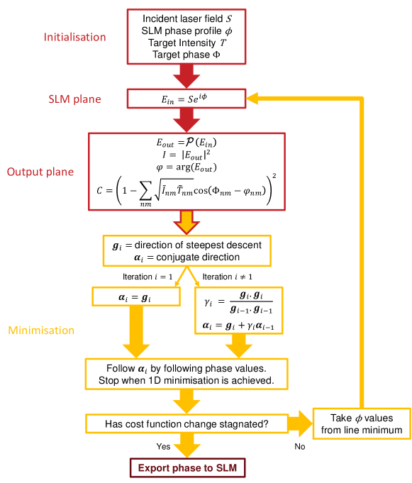
Figure 1 shows a diagrammatic representation of the calculation. The initial position in the parameter space of is determined by (a two-dimensional Gaussian profile with -radius ) and a guess phase . The two terms in respectively control the size and position of the envelope of the output plane intensity. This combination of phase patterns is known to suppress the formation of optical vortices during hologram calculation, which can otherwise cause premature stagnation and low accuracy Senthilkumaran+05 ; Pasienski+08 .
As an initial step, we calculate for each pixel to determine the direction of steepest descent and minimise along this direction to change . For subsequent iterations of the process, the descent direction is the conjugate direction
| (5) |
The process continues until the cost function stagnates (i.e. when the difference in the value of the cost function between iterations is below ) or a predefined maximum number of iterations is reached. We implement the conjugate gradient calculation in Python with the cost function gradient determined using the Theano library Theano .
III Numerical Results
We test our method on a range of target patterns particularly chosen with applications in optical trapping in mind. Independent spatial control over both the amplitude and phase of trap light is also increasingly desirable in the field of ultracold atoms, for example in the transfer of orbital angular momentum from light to atoms Ramanathan+11 , and in the creation of artificial gauge fields Huo+14 ; Lembessis+15 ; Butera+16 . In the particular case of trapping ultracold atoms in continuous geometries Pasienski+08 ; Bruce+11 ; Gaunt+12 ; Bowman+15 ; Bruce+15 ; Buccheri+16 , accuracy and smoothness of the intensity are vital to avoid fragmentation.
We calculate a pattern of phase values between 0 and for the SLM plane of pixels (with a pixel size of ) padded with zeros in the border such that the plane is pixels, such that there is no loss of resolution in the resulting output plane. The patterns are diagonally offset from the center of the plane by 85 pixels to avoid the zeroth order (undiffracted light) that would appear due to the finite efficiency of the SLM. This constrains two of the initialisation parameters to and .
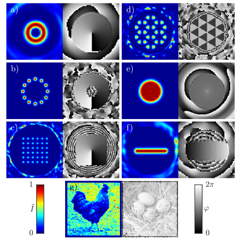
We show the region of interest of the calculated intensity and phase for each of our target patterns in Figure 2. The pattern similar to a Laguerre-Gaussian (LG) mode provides a good benchmark for our method and such patterns have a wide variety of uses Yao+11 , including in ultracold atom experiments to induce circulation states Ramanathan+11 . We can also retain the phase structure of LG modes but with arbitrary amplitude profiles. As examples, ring and square lattices with underlying phase windings have potential applications for quantum simulation of magnetic flux in solid state systems Huo+14 . Ultracold atoms confined in a honeycomb lattice with alternating phase between nearest neighbouring sites have also been shown to experience an artificial gauge field in a graphene quantum simulator Lembessis+15 , while a trapping potential comprising a flat intensity profile and an inverse square power-law phase has been proposed for investigations on sonic horizons and artificial black holes Butera+16 . A Gaussian line with a phase gradient across it can be used to trap particles in optical tweezers, but at the same time cause them to flow Roichman+08 . As a test of our method’s versatility, we have also chosen the more arbitrary patterns of a chicken and eggs Chicken which have uncorrelated intensity and phase patterns.
The main metric for accuracy is the fidelity, which is defined as Goorden+14 and is evaluated over non-zero amplitude within the measure region. The light efficiency () is the fraction of light in the output plane that is in the region of interest. A relative phase error within the measure region and the non-uniformity error for regions in the patterns that have a flat intensity Wu+15 are defined as:
| (6) | ||||
| (7) |
where is a correction term to account for the cyclical nature of the phase, is a binary mask which is equal to one where the target intensity is approximately uniform and zero everywhere else and is the average output intensity in the uniform region ( is the total number of pixels in the measure region).
| Pattern | ROI | ||||||
|---|---|---|---|---|---|---|---|
| mm | mrad px-2 | px | % | % | % | ||
| a) Laguerre Gauss | 1.0 | 4.5 | 42 | 41.5 | 0.0003 | 0.005 | |
| b) Square Lattice | 1.2 | 4.5 | 124 | 10.6 | 0.00009 | 0.02 | |
| c) Ring Lattice | 1.2 | 3.9 | 71 | 24.6 | 0.00006 | 0.001 | |
| d) Graphene | 1.4 | 2.7 | 78 | 13.1 | 0.0003 | 0.010 | |
| e) Flat Top | 1.0 | 4.5 | 63 | 11.3 | 0.2 | 0.007 | |
| f) Gaussian Line | 1.4 | 2.9 | 45 | 20.4 | 0.01 | 0.002 | |
| g) Chicken & Egg | 1.6 | 4.5 | 128 | 2.0 | 1.3 | - |
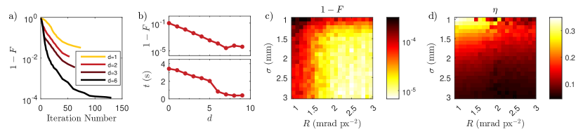
For the example of the Gaussian line pattern (with and ) Figure 3a) shows the evolution of the fidelity through the calculation for different values of the steepness parameter in Equation (4). Lower values of cause early stagnation of the algorithm into poor quality local minima. The maximum iteration number was reached for , whilst the fidelity would increase at approximately the same rate for (only and are shown in Figure 3 for clarity). It was found that a steeper cost function would not only lead to improved fidelities in the patterns, but also faster calculation times per iteration (Figure 3b)). A typical minimization routine converges in iterations at a total duration of with a standard desktop computer ( processor). For all patterns shown in this article, we have used .
For each pattern we perform an optimisation over the initialization conditions and (see Figure 3c)-d)). It was found that smaller incident laser beam sizes and reduced curvature in the guess phase led to higher light efficiency at a reduced fidelity. The beam size and curvature for the patterns in Figure 2 were chosen to provide both good light efficiency whilst maintaining a high fidelity. The optimal values of calculated holograms are shown in Table 1.
The authors of Wu+15 recently developed an IFTA for full-plane control of amplitude and phase, which they compared to a previous regionally-constrained algorithm Tao+15 . They find that the regionally-constrained algorithm is more accurate at the cost of light-utilisation efficiency, which has also been seen in amplitude-only control algorithms Pasienski+08 ; Harte+14 and in the present work. For far-field holograms of lines of continuous intensity with phase gradients, the regional algorithm gives , and , while the full-plane IFTA is less accurate ( and ) but achieves higher efficiency (). For our chosen cost function in Equation (4), the comparable continuous patterns amongst our range of targets (i.e. the Gaussian Line and Flat Top) are significantly smoother: we find is lower by a factor 6-20 and is lower by one or two orders of magnitude than the regional IFTA. The light-utilisation of the conjugate gradient optimised patterns is a factor 3-11 times higher than the regional IFTA, but between - of the full-plane IFTA. We note that the freedom in choice of the cost function terms and their relative weightings could be exploited to prioritise the efficiency of light usage at the expense of accuracy or smoothness if this is of greater importance to a particular application.
IV Experimental Verification
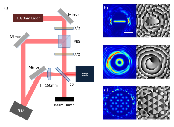
We verify the calculated holograms experimentally using the setup shown in Figure 4a). The output of a fiber laser (IPG YLP-5-1070-LP) is expanded to an experimentally-convenient waist of and split using a polarising beam splitter. One path is phase-modulated as it is reflected ( AOI) by a liquid crystal SLM (BNS P1920) and focussed onto a CCD camera (Thorlabs DCU200 Series) using an achromatic doublet. The other path gives a reference beam which is optionally recombined with the modulated beam after the focussing optic to produce interference fringes which are used to extract the phase of the modulated light via the Fourier transform fringe analysis method Takeda+82 .
As shown in Figure 4b)-d) and detailed in Table 2, the measured fidelities are lower than the numerical predictions, but could be improved by the addition of feedback Bruce+11 ; Bruce+15 or the characterisation of wavefront aberration in the optical system Cizmar+10 ; Zupancic+16 . We include the rescaled efficiency , which is , due to the diffraction efficiency of the SLM. Higher diffraction efficiencies could be obtained by replacing the SLM with a micro-fabricated diffractive optical element.
| Theory | Experiment | |||||||
|---|---|---|---|---|---|---|---|---|
| Pattern | ||||||||
| % | % | % | % | % | % | |||
| Gaussian Line | 0.99996 | 8.3 | 0.005 | 0.004 | 0.97 | 7.8 | 2.76 | 0.48 |
| Laguerre Gauss | 0.99999 | 8.4 | 0.0004 | 0.004 | 0.97 | 7.8 | 2.59 | 0.52 |
| Graphene | 0.9996 | 7.0 | 0.0004 | 0.015 | 0.96 | 6.2 | 1.85 | 0.42 |
V Conclusion
We have demonstrated that smooth, high fidelity light patterns with independent control over the amplitude and phase can be generated with a single phase-only SLM. The holograms calculated with the conjugate gradient minimisation approach surpass the accuracy and smoothness of previous IFTA approaches. We note that our approach achieves comparable results in and for image-quality holograms to the super-pixel method for DMDsGoorden+14 , and improved for the LG mode, at the expense of constraining the pattern to a subset of the output plane.
This approach to hologram calculation is compatible with existing methods for the generation of multi-wavelength holographic optical traps Bowman+15 . In this work we have concentrated on using a fast Fourier transform as the propagator . However, we find that near-field patterns calculated using Angular Spectrum Wavefront Propagation Goodman+96 achieve comparable fidelity, efficiency and smoothness. The accurate control over amplitude and phase will be crucial to a future research direction in the design of axially-structured light fields.
Funding
Leverhulme Trust (RPG-2013-074); EPSRC (EP/G03673X/1; EP/L015110/1).
Acknowledgments
We thank L. Walker and T. Doherty for useful discussions and T. Scrivener and P. Collins for the loan of the SLM.
References
- (1) M. Woerdemann, C. Alpmann, M. Esseling, and C. Denz, “Advanced optical trapping by complex beam shaping,” Laser Photon. Rev. 7, 839–854 (2013).
- (2) C. Maurer, A. Jesacher, S. Bernet, and M. Ritsch-Marte, “What spatial light modulators can do for optical microscopy,” Laser Photon. Rev. 5, 81–101 (2011).
- (3) A. E. Willner, H. Huang, Y. Yan, Y. Ren, N. Ahmed, G. Xie, C. Bao, L. Li, Y. Cao, Z. Zhao, J. Wang, M. P. J. Lavery, M. Tur, S. Ramachandran, A. F. Molisch, N. Ashrafi, and S. Ashrafi, “Optical communications using orbital angular momentum beams,” Adv. Opt. Photon. 7, 66–106 (2015).
- (4) L. G. Neto, D. Roberge, and Y. Sheng, “Full-range, continuous, complex modulation by the use of two coupled-mode liquid-crystal televisions,” Appl. Opt. 35, 4567–4576 (1996).
- (5) A. Jesacher, C. Maurer, A. Schwaighofer, S. Bernet, and M. Ritsch-Marte, “Full phase and amplitude control of holographic optical tweezers with high efficiency,” Opt. Express 16, 4479–4486 (2008).
- (6) L. Zhu and J. Wang, “Arbitrary manipulation of spatial amplitude and phase using phase-only spatial light modulators,” Sci. Rep. 4, 7441 (2014).
- (7) Y. Roichman and D. G. Grier, “Projecting extended optical traps with shape-phase holography,” Opt. Lett. 31, 1675–1677 (2006).
- (8) T. W. Clark, R. F. Offer, S. Franke-Arnold, A. S. Arnold, and N. Radwell, “Comparison of beam generation techniques using a phase only spatial light modulator,” Opt. Express 24, 6249–6264 (2016).
- (9) S. A. Goorden, J. Bertolotti, and A. P. Mosk, “Superpixel-based spatial amplitude and phase modulation using a digital micromirror device,” Opt. Express 22, 17999–18009 (2014).
- (10) J. Goodman, Introduction to Fourier Optics (McGraw-Hill, 1996).
- (11) S. Tao and W. Yu, “Beam shaping of complex amplitude with separate constraints on the output beam,” Opt. Express 23, 1052–1062 (2015).
- (12) L. Wu, S. Cheng, and S. Tao, “Simultaneous shaping of amplitude and phase of light in the entire output plane with a phase-only hologram,” Sci. Rep. 5, 15426 (2015).
- (13) T. Harte, G. D. Bruce, J. Keeling, and D. Cassettari, “Conjugate gradient minimisation approach to generating holographic traps for ultracold atoms,” Opt. Express 22, 26548–26558 (2014).
- (14) J. R. Shewchuk, An introduction to the conjugate gradient method without the agonizing pain (Carnegie Mellon University, 1994).
- (15) M. Pasienski and B. DeMarco, “A high-accuracy algorithm for designing arbitrary holographic atom traps,” Opt. Express 16, 2176–2190 (2008).
- (16) P. Senthilkumaran, F. Wyrowski, and H. Schimmel, “Vortex stagnation problem in iterative Fourier transform algorithms,” Opt. Laser Eng. 43, 43–56 (2005).
- (17) Theano Development Team, “Theano: A Python framework for fast computation of mathematical expressions,” arXiv:1605.02688 (2016).
- (18) A. Ramanathan, K. C. Wright, S. R. Muniz, M. Zelan, W. T. Hill III, C. J. Lobb, K. Helmerson, W. D. Phillips, and G. K. Campbell, “Superflow in a toroidal Bose-Einstein condensate: An atom circuit with a tunable-weak link,” Phys. Rev. Lett. 106, 130401 (2011).
- (19) M.-X. Huo, W. Nie, D. A. W. Hutchinson, and L. C. Kwek, “A solenoidal synthetic field and the non-Abelian Aharonov-Bohm effects in neutral atoms,” Sci. Rep. 4, 5992 (2014).
- (20) V. E. Lembessis, J. Courtial, N. Radwell, A. Selyem, S. Franke-Arnold, O. M. Aldossary, and M. Babiker, “Graphene-like optical light field and its interaction with two-level atoms,” Phys. Rev. A92, 063833 (2015).
- (21) S. Butera, N. Westerberg, D. Faccio, and P. Öhberg, “Nonlinear synthetic gauge potentials and sonic horizons in Bose-Einstein condensates,” arXiv:1605.05556 (2016).
- (22) G. D. Bruce, J. Mayoh, G. Smirne, L. Torralbo-Campo, and D. Cassettari, “Smooth, holographically generated ring trap for the investigation of superfluidity in ultracold atoms,” Phys. Scr. T143, 014008 (2011).
- (23) A. L. Gaunt and Z. Hadzibabic, “Robust digital holography for ultracold atom trapping,” Sci. Rep. 2, 721 (2012).
- (24) D. Bowman, P. Ireland, G. D. Bruce, and D. Cassettari, “Multi-wavelength holography with a single spatial light modulator for ultracold atom experiments,” Opt. Express 23, 8365–8372 (2015).
- (25) G. D. Bruce, M. Y. H. Johnson, E. Cormack, D. A. W. Richards, J. Mayoh, and D. Cassettari, “Feedback-enhanced algorithm for aberration correction of holographic atom traps,” J. Phys. B: At. Mol. Opt. Phys. 48, 115303 (2015).
- (26) F. Buccheri, G. D. Bruce, A. Trombettoni, D. Cassettari, H. Babujian, V. E. Korepin, and P. Sodano, “Feedback-enhanced algorithm for aberration correction of holographic atom traps,” New J. Phys. 18, 075012 (2016).
- (27) A. M. Yao and M. J. Padgett, “Orbital angular momentum: origins, behavior and applications,” Adv. Opt. Photon. 3, 161–204 (2011).
- (28) Y. Roichman, B. Sun, Y. Roichman, J. Amato-Grill, and D. G. Grier, “Optical forces arising from phase gradients,” Phys. Rev. Lett. 100, 013602 (2008).
- (29) Images downloaded from Wikimedia Commons, 11/11/16
- (30) M. Takeda, H. Ina, and S. Kobayashi, “Fourier-transform method of fringe-pattern analysis for computer-based topography and interferometry,” J. Opt. Soc. Am. 72, 156–160 (1982).
- (31) T. Čižár, M. Mazilu, and K. Dholakia, “In situ wavefront correction and its application to micromanipulation,” Nat. Photon. 4, 388–394 (2010).
- (32) P. Zupancic, P. M. Preiss, R. Ma, A. Lukin, M. E. Tai, M. Rispoli, R. Islam, and M. Greiner, “Ultra-precise holographic beam shaping for microscopic quantum control,” Opt. Express 24, 13881–13893 (2016).