Current-driven skyrmion dynamics in disordered films
Abstract
A theoretical study of the current-driven dynamics of magnetic skyrmions in disordered perpendicularly-magnetized ultrathin films is presented. The disorder is simulated as a granular structure in which the local anisotropy varies randomly from grain to grain. The skyrmion velocity is computed for different disorder parameters and ensembles. Similar behavior is seen for spin-torques due to in-plane currents and the spin Hall effect, where a pinning regime can be identified at low currents with a transition towards the disorder-free case at higher currents, similar to domain wall motion in disordered films. Moreover, a current-dependent skyrmion Hall effect and fluctuations in the core radius are found, which result from the interaction with the pinning potential.
Magnetic skyrmions are nanoscale spin configurations with a nontrivial topology. Bogdanov and Rößler (2001); Heinze et al. (2011); Romming et al. (2013) In ultrathin ferromagnets in contact with a strong spin-orbit material, they are stabilized by interfacial chiral interactions of the Dzyaloshinskii-Moriya form (DMI) Dupé et al. (2014, 2016) and possess core sizes down to the nanometer range. Romming et al. (2015) Skyrmions can be moved by spin currents and their dynamics depends on their topological properties. Komineas and Papanicolaou (2015); Yamane and Sinova (2016) They have been touted as promising candidates for various spintronics applications, such as racetrack memories Fert, Cros, and Sampaio (2013); Tomasello et al. (2014) and microwave detectors, Finocchio et al. (2015) and offer possible advantages over domain-wall–based systems because they are less susceptible to certain defects. Fert, Cros, and Sampaio (2013); Sampaio et al. (2013); Iwasaki, Mochizuki, and Nagaosa (2013) Recent experiments have confirmed the existence of room-temperature skyrmions in sputtered multilayer systems, Jiang et al. (2015); Moreau-Luchaire et al. (2016); Boulle et al. (2016); Woo et al. (2016); Hrabec et al. (2016); Legrand et al. (2017) which is an important milestone toward realizing skyrmion-based devices.
For interface-driven DMI, most material systems investigated to date involve ultrathin ferromagnets with perpendicular magnetic anisotropy. These systems have also been studied extensively for magnetic domain wall dynamics, Metaxas et al. (2007); Miron et al. (2011); Ryu et al. (2013); Emori et al. (2013); Hrabec et al. (2014); Torrejon et al. (2014) where observations of strong pinning are common. In the context of skyrmion dynamics, it is natural to enquire whether the same disorder that leads to wall pinning can also have an influence on skyrmion propagation. Experimentally, it has been established that pinning can be strong. Hanneken et al. (2016) While the effects of boundary edges on skyrmion propagation have been studied, Fert, Cros, and Sampaio (2013); Sampaio et al. (2013) studies of the role of random disorder to date have been limited to atomistic Iwasaki, Mochizuki, and Nagaosa (2013); Müller and Rosch (2015) or particle-based models. Lin et al. (2013); Reichhardt, Ray, and Reichhardt (2015); Reichhardt and Reichhardt (2016)
Here, we revisit the problem by using micromagnetics simulations to model more realistic disorder that is relevant to ultrathin films. Specifically, the disorder is modeled as local variations in the perpendicular anisotropy and the current-driven motion due to current-in-plane and spin Hall effect torques are considered. We find significant pinning at low applied currents and additional contributions to the skyrmion Hall effect that arises from interaction with the disorder potential, which is consistent with previous studies. Müller and Rosch (2015); Reichhardt and Reichhardt (2016) We also examine how the skyrmion core is deformed as it traverses the disorder potential.
We used the MuMax3 code Vansteenkiste et al. (2014) for the micromagnetics simulations. The code integrates numerically the Landau-Lifshitz equation with Gilbert damping and spin torques,
| (1) |
where is a unit vector representing the magnetization state, is the effective field, is the gyromagnetic constant, is the permeability of free space, is the damping constant, and represents spin torques. We model a perpendicularly-magnetized ferromagnetic film with a thickness of nm. In Cartesian coordinates, the plane represents the film plane and is the direction of the uniaxial anisotropy, perpendicular to the film plane. We assumed an exchange constant of pJ/m, a uniaxial anisotropy of MJ/m3, and a saturation magnetization of MA/m. These parameters are consistent with the values obtained for ultrathin Co in Pt/Co/AlOx multilayers, Belmeguenai et al. (2015) which exhibit a strong DMI. For the dynamics we assumed , which is consistent with recent experiments. Schellekens et al. (2013) In order to simulate disorder, we considered a random grain structure in which the local anisotropy of each grain , , is drawn from a Gaussian distribution centered on the mean value with a standard deviation of . Voto, Lopez-Diaz, and Torres (2016); Garcia-Sanchez et al. (2016) The grain structure is constructed using Voronoi tessellation and different average grain sizes, , are considered.
Before examining the skyrmion dynamics in detail, we first discuss how such disorder can be related to observable quantities in experiment. A direct means to characterize the disorder is through the depinning field, , for magnetic domain wall propagation. This is defined as the threshold field at which a magnetic domain wall can propagate freely without being impeded by any pinning (and corresponds to the situation in which the force acting on the wall is the same sign everywhere). It is a quantity that is readily accessible experimentally for continuous films, so it represents a useful measure of the disorder to which simulations can be benchmarked. Results of micromagnetics simulations of are shown in Fig. 1.
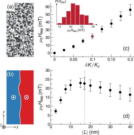
The simulations are performed for a system with lateral dimensions of 0.5 m 1.0 m that is discretized using 51210241 finite difference cells (the magnetization is assumed to be uniform across the film thickness). An example of the grain structure with nm is given in Fig. 1(a). The initial micromagnetic state consists of two domains, one oriented along for and the other along for , which results in a domain wall running across the width () of the system. Periodic boundary conditions are applied along to avoid edge effects. The initial state is then relaxed using energy minimization, which results in a rugged domain wall structure [Fig. 1(b)]. Next, a magnetic field is applied along and increased incrementally, where at each field step the equilibrium configuration is found using energy minimization. This proceeds until the domain wall is completely depinned and sweeps across the system, resulting in a uniformly magnetized state along . We designate as the field at which this occurs. For each set of and , the simulations are repeated for 100 different realizations of the disorder so that ensemble averages can be obtained.
The dependence of the depinning field on the anisotropy variation is shown in Fig. 1(c). A monotonic increase is seen, which can be expected since larger variations in the anisotropy are likely to result in larger spatial variations in the energy landscape and therefore stronger pinning. The error bars correspond to one standard deviation of the pinning field distribution, where the distribution for is given in the inset of Fig. 1(c). In Fig. 1(d), the variation of with the average grain size (for ) is shown. Unlike for anisotropy fluctuations, the variation is non-monotonic and exhibits a peak around nm, which is preceded by a rapid increase and followed by a slower decrease as is increased. On this plot, the domain wall width, , where is the effective perpendicular anisotropy, is shown and roughly coincides with the position of the maximum in the pinning field. We can understand this result as follows. For sufficiently small grains, , the anisotropy variations are averaged out over the wall width and therefore the pinning potential is smoothed out, leading to low pinning fields. At the opposite limit, , the domain wall traverses larger regions in which the anisotropy remains constant, so the pinning field in that case is predominantly determined by step changes in the anisotropy at grain boundaries. Note that is relevant to skyrmions, since it is also characteristic scale of the double-soliton ansatz Braun (1994) that describes the skyrmion core profile. Romming et al. (2015)
We now discuss the role of anisotropy disorder on current-driven skyrmion dynamics. We model a system with dimensions of 0.5 m 0.5 m 0.6 nm that is discretized with 5125121 finite difference cells. Periodic boundary conditions are assumed along and , which mimics an infinite system and avoids edge boundary effects. Yoo, Cros, and Kim (2017) The skyrmion Hall effect ensures that the motion is not parallel to the simulation grid ( or ), which allows different grains to be traversed as the skyrmion wraps around the simulation grid. We assume a DMI constant of mJ/m2, which is consistent with experimental results. Belmeguenai et al. (2015)
The simulations are performed as follows. For each realization of the disorder, the initial configuration comprises a single Néel-type skyrmion at the center of the simulation grid, with the core magnetization oriented toward and the uniform background magnetization along . The simulation is run for 10 ns at a given current density and the skyrmion displacement is computed over this interval. This is performed for 50 different realizations of the disorder for each applied current density. While no thermal fluctuations are taken into account (to minimize computation time), the simulations mimic experiments in which observations are only made after successive current pulses are applied. Moreover, thermal activation in real systems would result in different starting points prior to each pulse, which is accounted for here with our ensemble averaging of the disorder. We note that skyrmion annihilation occurs under certain conditions (large currents, strong disorder); for such cases, the averages are performed only for the duration for which the skyrmion is present.
In Fig. 2, we present the average skyrmion velocity as a function of current-induced spin Hall torques for different disorder parameters.
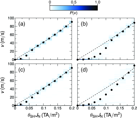
We assume a hypothetical current flows in an adjacent heavy-metal buffer layer, which generates a spin current polarized along that flows along into the ferromagnet. is the spin Hall angle of the heavy metal layer. This leads to a torque of the form
| (2) |
where is the electron charge. For the disorder parameters considered, we can identify a pinning regime at low current densities in which the average velocity is significantly below the value for the disorder-free case. This behavior is mainly determined by events for which the skyrmion becomes pinned by the disorder within the 10-ns simulation window, either at the onset or after a certain duration during which a finite displacement takes place. We present the probability density of the velocities as a color map, where significant spread can be seen for stronger disorder, as expected. We note that the exponential-like increase at low currents, followed by a smooth transition toward the disorder-free case, is typical of driven interface motion in disordered media, Chauve, Giamarchi, and Le Doussal (2000) such as domain wall propagation in perpendicular anisotropy materials. Metaxas et al. (2007) Our results therefore highlight the similarity with the depinning dynamics of domain walls and confirm that skyrmions are not impervious to defect-induced pinning for realistic disorder. We note that similar trends have been observed in recent experiments on current-driven skyrmion motion. Woo et al. (2016); Hrabec et al. (2016); Legrand et al. (2017)
In Fig. 3, we present the average skyrmion velocity as a function of in-plane applied currents.
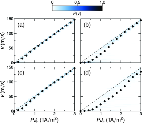
Here, the spin torques are related to the in-plane (CIP) flow of spin-polarized currents across magnetic textures, which involves adiabatic and nonadiabatic contributions, Zhang and Li (2004)
| (3) |
where is an effective spin drift velocity associated with the in-plane current (density) flowing through the ferromagnet, . We neglected the nonadiabatic term () for the simulation results shown in Fig. 3 as it only affects the intrinsic skyrmion Hall angle (under the rigid core assumption). Nevertheless, we have performed simulations to verify that a nonzero term does not change our findings. The torques are determined by the current density flowing through the ferromagnet with a spin polarization . To facilitate comparisons between the spin Hall torques and the CIP torques, we present results for current densities that result in a similar range of average velocities. Besides the obvious difference in spin torque efficiency, we note that the behavior is qualitatively similar for CIP torques where a transition between the pinning and disorder-free regimes can be seen.
The disorder potential strongly influences the direction of the skyrmion propagation. In Fig. 4, the trajectories for 50 different disorder realizations (, ) are shown for four values of .
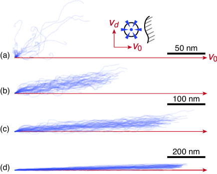
The trajectories are presented with the same initial position and relative to the propagation direction of the disorder-free case, which is along the horizontal axis denoted by . For the lowest current shown [Fig. 4(a)], we observe that most realizations lead to a pinned skyrmion close to its initial position, while only few cases of propagation over tens of nm are seen. We can also observe spirals in some of the trajectories, which possess the same handedness and results from the gyrotropic nature of the skyrmion motion. This is consistent with previous studies on skyrmion pinning. Liu and Li (2013) We note that the trajectories do not lead to an average displacement along , but rather at an appreciable angle [approximately 45∘ in Fig. 4(a)]. This result can be understood in terms of the gyrotropic response of a skyrmion to a force; as the skyrmion is driven toward a boundary edge (in our case, a defect-induced potential barrier), the restoring force due to this edge drives the skyrmion along a specific direction perpendicular to this force. As such, each time the skyrmion encounters a potential barrier whilst propagating along the direction, it experiences a restoring force along that results in an addition deflection along , perpendicular to . This extrinsic Hall motion becomes less pronounced as the current is increased [Figs. 4(b)-(d)], where the current-driven torques become sufficiently large to overcome the pinning potential. Note, however, that in most cases the trajectories exhibiting the largest displacements also exhibit the strongest deflection, which suggests that the skyrmion can circumvent strong potential barriers through the additional Hall motion. These results agree with an analytical approach in which the deflection is predicted within the rigid core approximation Müller and Rosch (2015) and particle simulations. Reichhardt and Reichhardt (2016)
The skyrmion core fluctuates in size as it traverses the disorder potential. In Fig. 5, we present the distribution of the average core radius, , for different applied spin Hall currents and disorder parameters, along with snapshots of the core profile.
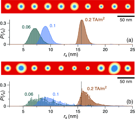
is computed using the double-soliton ansatz for the component, Braun (1994); Romming et al. (2015); Garcia-Sanchez et al. (2016) where we equate the area bound by the curve of the simulated profile with the radius that gives the same area using . The distribution is constructed from values taken at 20 ps intervals of each simulation run. We observe that can fluctuate over a range of nm as the skyrmion traverses the potential. The mean value depends on the applied current density, where stronger compressive effects are seen at lower currents at which pinning is dominant. This is analogous to the dynamics seen for propagation along boundary edges, where the combination between spin torques and the edge confinement leads to a reduction in the core size. Garcia-Sanchez et al. (2016); Yoo, Cros, and Kim (2017) For larger currents at which propagation approaches the disorder-free case, the mean value of is close to its equilibrium value (e.g., 0.2 TA/m2 in Fig. 5). Stronger pinning results in a wider distribution of , which is accompanied by larger deformations in the core profile [Fig. 5(b)].
These results highlight the outstanding challenges for devising reliable skyrmion-based devices. First, pinning due to realistic disorder cannot be neglected and the skyrmion topology alone is insufficient to negate such effects. The disorder parameters considered lead to domain wall pinning fields of tens of mT, which is typical of experimental systems. Second, the disorder leads to an extrinsic skyrmion Hall effect that is current-dependent. Device schemes that require control of the propagation direction should account for this issue. Müller (2017) Third, the core size fluctuates as the skyrmion propagates, which would lead to additional noise for detection schemes that rely on the surface area of reversed magnetization, such as tunnel magnetoresistance or stray magnetic fields. As these results suggest, optimizing material properties to minimize pinning (including domain walls) would represent a key step toward meeting these challenges. Alternatively, skyrmions in disordered systems could be useful for stochastic-based computing schemes. Mizrahi et al. (2016); Pinna et al. (2017)
Acknowledgements.
The authors acknowledge fruitful discussions with V. Cros, A. Hrabec, J. Müller, N. Reyren, S. Rohart, and R. Soucaille. The authors are grateful to A. Thiaville for hosting part of the computational cluster during the downtime of the C2N laboratory. This work was supported by the Agence Nationale de la Recherche (France) under Contract No. ANR-14-CE26-0012 (Ultrasky) and the Horizon2020 Framework Programme of the European Commission (H2020-FETOPEN-2014-2015-RIA) under Contract No. 665095 (MAGicSky).References
- Bogdanov and Rößler (2001) A. N. Bogdanov and U. K. Rößler, Phys. Rev. Lett. 87, 037203 (2001).
- Heinze et al. (2011) S. Heinze, K. von Bergmann, M. Menzel, J. Brede, A. Kubetzka, R. Wiesendanger, G. Bihlmayer, and S. Blügel, Nat. Phys. 7, 713 (2011).
- Romming et al. (2013) N. Romming, C. Hanneken, M. Menzel, J. E. Bickel, B. Wolter, K. Von Bergmann, A. Kubetzka, and R. Wiesendanger, Science 341, 636 (2013).
- Dupé et al. (2014) B. Dupé, M. Hoffmann, C. Paillard, and S. Heinze, Nat. Commun. 5, 4030 (2014).
- Dupé et al. (2016) B. Dupé, G. Bihlmayer, M. Böttcher, S. Blügel, and S. Heinze, Nat. Commun. 7, 11779 (2016).
- Romming et al. (2015) N. Romming, A. Kubetzka, C. Hanneken, K. von Bergmann, and R. Wiesendanger, Phys. Rev. Lett. 114, 177203 (2015).
- Komineas and Papanicolaou (2015) S. Komineas and N. Papanicolaou, Phys. Rev. B 92, 174405 (2015).
- Yamane and Sinova (2016) Y. Yamane and J. Sinova, J. Appl. Phys. 120, 233901 (2016).
- Fert, Cros, and Sampaio (2013) A. Fert, V. Cros, and J. Sampaio, Nat. Nanotechnol. 8, 152 (2013).
- Tomasello et al. (2014) R. Tomasello, E. Martinez, R. Zivieri, L. Torres, M. Carpentieri, and G. Finocchio, Sci. Rep. 4, 6784 (2014).
- Finocchio et al. (2015) G. Finocchio, M. Ricci, R. Tomasello, A. Giordano, M. Lanuzza, V. Puliafito, P. Burrascano, B. Azzerboni, and M. Carpentieri, Appl. Phys. Lett. 107, 262401 (2015).
- Sampaio et al. (2013) J. Sampaio, V. Cros, S. Rohart, A. Thiaville, and A. Fert, Nat. Nanotechnol. 8, 839 (2013).
- Iwasaki, Mochizuki, and Nagaosa (2013) J. Iwasaki, M. Mochizuki, and N. Nagaosa, Nat. Nanotechnol. 8, 742 (2013).
- Jiang et al. (2015) W. Jiang, P. Upadhyaya, W. Zhang, G. Yu, M. B. Jungfleisch, F. Y. Fradin, J. E. Pearson, Y. Tserkovnyak, K. L. Wang, O. Heinonen, S. G. E. te Velthuis, and A. Hoffmann, Science 349, 283 (2015).
- Moreau-Luchaire et al. (2016) C. Moreau-Luchaire, C. Moutafis, N. Reyren, J. Sampaio, C. A. F. Vaz, N. Van Horne, K. Bouzehouane, K. Garcia, C. Deranlot, P. Warnicke, P. Wohlhüter, J.-M. George, M. Weigand, J. Raabe, V. Cros, and A. Fert, Nat. Nanotechnol. 11, 444 (2016).
- Boulle et al. (2016) O. Boulle, J. Vogel, H. Yang, S. Pizzini, D. de Souza Chaves, A. Locatelli, T. O. Menteş, A. Sala, L. D. Buda-Prejbeanu, O. Klein, M. Belmeguenai, Y. Roussigné, A. Stashkevich, S. M. Cherif, L. Aballe, M. Foerster, M. Chshiev, S. Auffret, I. M. Miron, and G. Gaudin, Nat. Nanotechnol. 11, 449 (2016).
- Woo et al. (2016) S. Woo, K. Litzius, B. Krüger, M.-Y. Im, L. Caretta, K. Richter, M. Mann, A. Krone, R. M. Reeve, M. Weigand, P. Agrawal, I. Lemesh, M.-A. Mawass, P. Fischer, M. Kläui, and G. S. D. Beach, Nat. Mater. 15, 501 (2016).
- Hrabec et al. (2016) A. Hrabec, J. Sampaio, M. Belmeguenai, I. Gross, R. Weil, S. M. Cherif, A. Stachkevitch, V. Jacques, A. Thiaville, and S. Rohart, arXiv:1611.00647 [cond-mat.mes-hall] (2016).
- Legrand et al. (2017) W. Legrand, D. Maccariello, K. Reyren, N Garcia, C. Moutafis, C. Moreau-Luchaire, S. Collin, K. Bouzehouane, V. Cros, and A. Fert, “Room-temperature current-induced generation and motion of sub-100nm skyrmions,” (2017), unpublished.
- Metaxas et al. (2007) P. Metaxas, J.-P. Jamet, A. Mougin, M. Cormier, J. Ferré, V. Baltz, B. Rodmacq, B. Dieny, and R. L. Stamps, Phys. Rev. Lett. 99, 217208 (2007).
- Miron et al. (2011) I. M. Miron, T. Moore, H. Szambolics, L. D. Buda-Prejbeanu, S. Auffret, B. Rodmacq, S. Pizzini, J. Vogel, M. Bonfim, A. Schuhl, and G. Gaudin, Nat. Mater. 10, 419 (2011).
- Ryu et al. (2013) K.-S. Ryu, L. Thomas, S.-H. Yang, and S. Parkin, Nat. Nanotechnol. 8, 527 (2013).
- Emori et al. (2013) S. Emori, U. Bauer, S.-M. Ahn, E. Martinez, and G. S. D. Beach, Nat. Mater. 12, 611 (2013).
- Hrabec et al. (2014) A. Hrabec, N. A. Porter, A. Wells, M. J. Benitez, G. Burnell, S. McVitie, D. McGrouther, T. A. Moore, and C. H. Marrows, Phys. Rev. B 90, 020402 (2014).
- Torrejon et al. (2014) J. Torrejon, J. Kim, J. Sinha, S. Mitani, M. Hayashi, M. Yamanouchi, and H. Ohno, Nat. Commun. 5, 1 (2014).
- Hanneken et al. (2016) C. Hanneken, A. Kubetzka, K. von Bergmann, and R. Wiesendanger, New J. Phys. 18, 1 (2016).
- Müller and Rosch (2015) J. Müller and A. Rosch, Phys. Rev. B 91, 054410 (2015).
- Lin et al. (2013) S.-Z. Lin, C. Reichhardt, C. D. Batista, and A. Saxena, Phys. Rev. B 87, 214419 (2013).
- Reichhardt, Ray, and Reichhardt (2015) C. Reichhardt, D. Ray, and C. J. O. Reichhardt, Phys. Rev. Lett. 114, 217202 (2015).
- Reichhardt and Reichhardt (2016) C. Reichhardt and C. J. O. Reichhardt, New J. Phys. 18, 1 (2016).
- Vansteenkiste et al. (2014) A. Vansteenkiste, J. Leliaert, M. Dvornik, M. Helsen, F. García-Sánchez, and B. Van Waeyenberge, AIP Adv. 4, 107133 (2014).
- Belmeguenai et al. (2015) M. Belmeguenai, J.-P. Adam, Y. Roussigné, S. Eimer, T. Devolder, J.-V. Kim, S. M. Cherif, A. Stashkevich, and A. Thiaville, Phys. Rev. B 91, 180405 (2015).
- Schellekens et al. (2013) A. J. Schellekens, L. Deen, D. Wang, J. T. Kohlhepp, H. J. M. Swagten, and B. Koopmans, Appl. Phys. Lett. 102, 082405 (2013).
- Voto, Lopez-Diaz, and Torres (2016) M. Voto, L. Lopez-Diaz, and L. Torres, J. Phys. D: Appl. Phys. 49, 1 (2016).
- Garcia-Sanchez et al. (2016) F. Garcia-Sanchez, J. Sampaio, N. Reyren, V. Cros, and J.-V. Kim, New J. Phys. 18, 075011 (2016).
- Braun (1994) H.-B. Braun, Phys. Rev. B 50, 16485 (1994).
- Yoo, Cros, and Kim (2017) M.-W. Yoo, V. Cros, and J.-V. Kim, “Current-driven skyrmion expulsion from magnetic nanostrips,” arXiv:1702.05672 [cond-mat.mes-hall] (2017).
- Chauve, Giamarchi, and Le Doussal (2000) P. Chauve, T. Giamarchi, and P. Le Doussal, Phys. Rev. B 62, 6241 (2000).
- Zhang and Li (2004) S. Zhang and Z. Li, Phys. Rev. Lett. 93, 127204 (2004).
- Liu and Li (2013) Y.-H. Liu and Y.-Q. Li, J. Phys. Condens. Matter 25, 076005 (2013).
- Müller (2017) J. Müller, New J. Phys. 19, 025002 (2017).
- Mizrahi et al. (2016) A. Mizrahi, N. Locatelli, R. Lebrun, V. Cros, A. Fukushima, H. Kubota, S. Yuasa, D. Querlioz, and J. Grollier, Sci. Rep. 6, 30535 (2016).
- Pinna et al. (2017) D. Pinna, F. Abreu Araujo, J.-V. Kim, V. Cros, D. Querlioz, P. Bessiere, J. Droulez, and J. Grollier, “Skyrmion Gas Manipulation for Probabilistic Computing,” arXiv:1701.07750 [cond-mat.mes-hall] (2017).