Comment on “Eshelby twist and correlation effects in diffraction from nanocrystals “ [J. Appl. Phys. 117, 164304 (2015)]
Abstract
The aim of this comment is mainly to show that anisotropic effects and image fields should not be omitted as they are in the publication of A. Leonardi, S. Ryu, N. M. Pugno, and P. Scardi (LRPS) [J. Appl. Phys. 117, 164304 (2015)] on Palladium cylindrical nanowires containing an axial screw dislocation . Indeed, according to our previous study [Phys. Rev. B 88, 224101 (2013)], the axial displacement field along the nanowire exhibits both a radial and an azimuthal dependence with a twofold symmetry due the orientation. is made of the superposition of three anisotropic fields : the screw dislocation field in an infinite medium, the warping displacement field caused by the so-called Eshelby twist and an additional image field induced by the free surfaces. As a consequence by ignoring both anisotropy and image fields, the deviatoric strain term used by LRPS is not suitable to analyze the anisotropic strain fields that should be observed in their Molecular Dynamics simulations. In this comment, we first illustrate the importance of anisotropy in Pd nanowire by calculating the azimuthal dependence of the deviatoric strain term. Then the expression of the anisotropic elastic field is recalled in term of strain tensor components to show that image fields should be also considered.
The other aspect of this comment concerns the supposedly loss of correlation along the nanorod caused by the twist. It is claimed for instance by LRPS that : “As an effect of the dislocation strain and twist, if the cylinder is long enough, upper/lower regions tend to lose correlation, as if the rod were made of different sub-domains.”. This assertion that is repeatedly restated along the manuscript appears to us misleading since for any twist the position of all the atoms in the nanorod is perfectly defined and therefore prevents any loss of correlation. To clarify this point, it should be specified that this apparent loss of correlation can not be ascribed to the twisted state of the nanowire but is rather due to a limitation of the X-ray powder diffraction combined with the Whole Powder Pattern Modeling (WPPM). Considering for instance coherent X-ray diffraction, we show an example of high twist where the simulated diffractogram presents a clear signature of the perfect correlation.
I Anisotropic strain field induced by an axial screw dislocation in a fcc metal nanowire
The displacement field induced by an axial screw dislocation in a fcc metal nanowire has been studied in detail recently.Gailhanou and Roussel (2013) For a circular cross section, the field presents the two-fold symmetry of the orientation with an azimuthal dependence that is controlled by the anisotropy of the shear modulus. This latter is significant for Palladium since like in the case of Copper Gailhanou and Roussel (2013) the values of the elastic moduli are similar with GPa and GPa in the coordinate system.
To illustrate the importance of these anisotropic effects, let us calculate the azimuthal dependence of two particular quantities discussed in the article of LRPSLeonardi et al. (2015) (and reported in their Figure 6d), namely the deviatoric strain term due to the screw deformation only and the one due to the twist only. These latter, denoted here and respectively, are plotted in Figure 1 as a function of the radial distance but also for all azimuth .
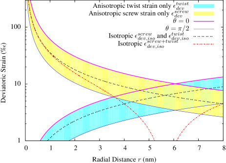
Clearly the azimuthal exploration shows that both and belong to large domains bounded by extremum values (for and ) that differ by a ratio equal to .
Incidentally, we wish to comment the analysis made of the deviatoric strain terms in the Figure 6d, that leads the authors to conclude at the end of section III: “…, so that the combined effect (screw and twist) gets closer to the MD simulation.”. This assertion is doubly misleading. First of all because the MD simulation curve must contain the above mentioned anisotropy which is not shown on this graph (some clarification on the method used to get the MD curve would be helpful). And secondly because the isotropic deviatoric strain term designated as “Screw and Twist deformation field” in Figure 6d does not match a calculation of the combined effect of both the dislocation and the torsion. The plot of this term denoted as in Figure 1 of the present work reveals a very different behavior since should vanish for , being the nanowire radius. This result can be directly understood by examining the and strain components in this isotropic case: the are null for both the dislocation and the torsion but the components have opposite signs with and where is the magnitude of the Burgers vector.Eshelby (1953); Hirth and Lothe (1982) Consequently, since , one gets . Thus, for approaching the combined effect (screw and twist) gets far away from the MD simulations shown by the authors.
To conclude this section, we provide the expressions of the strain components and leading to the anisotropic behavior reported in Figure 1. We also derive from our previous work Gailhanou and Roussel (2013) the additional image strain field that results from the interaction of the screw dislocation with the lateral surfaces of the anisotropic cylinder.
Having determined the equilibrium stress components and in Ref.[Gailhanou and Roussel, 2013], the derivation of the strain field becomes straightforward by using the following relations:
| (1) |
where the elastic moduli can be written as , and with and .
Thus, the strain field induced by a perfect Volterra screw dislocation, with Burgers vector b = 1/2 is inversely proportional to with a marked dependence:
| (2) |
The twist of the nanowire that is necessary to cancel the torque due to the dislocation produces a stress component ( is null for a circular cylinder) that in term of strain becomes :
| (3) |
Finally, in the present case of an anisotropic nanowire of circular cross section containing a coaxial screw dislocation, an image stress field is necessary to fulfill the condition of a vanishing traction at the lateral surface. Formally, this condition reduces to because is null for a circular cross section.
Thus, looking for an image field that obeys both to the boundary conditions, the equilibrium and the compatibility equations, we could obtain a numerical solution of the stress field based on a Fourier series analysis. Approximate expressions of and were also proposed in Ref.[Gailhanou and Roussel, 2013]. Using Eqs.(1), these latter can be converted in term of strain and written as :
| (4) |
with is equal to .
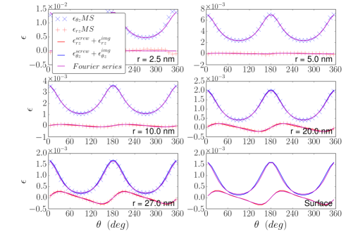
In Ref.[Gailhanou and Roussel, 2013], the image field derived in term of stress components was compared to the one calculated from Molecular Statics simulations (MS). Similarly in the present comment, the MS simulations can serve as a reference for testing the validity of the approximate expression given in Eqs.(4) of the image strain. In practice, the analyticity of the Tight Binding potential used in our atomistic simulations allows a straightforward determination of the strain components per atom. This is illustrated in Figure 2 where the radial and the azimuthal dependencies of the strain field components and resulting from our MS simulations are plotted in the case of an untwisted Cu nanowire of radius 30 nm containing a screw dislocation at its center (the torsion can be treated separately since it does not affect the image field for a circular cross section). As for the stress analysis, the same conclusions can be drawn. The dislocation field in Eq. (2) combined with the image field in Eq. (4) capture well the radial dependence and the azimuthal anisotropy of the strain field found in our simulations. This anisotropy is particularly pronounced for Copper (as for Palladium). It controls for instance the shape of the Eshelby potential well that traps the screw dislocation at the center of the twisted nanowire.Roussel and Gailhanou (2015)
II Diffraction from a twisted cylinder
At the end of their article, LRPS arrive at the conclusion that “the twist weakens the correlation between more distant regions of the cylindrical domain, up to the point that needle-like nanocrystals appear as made of sub-domains (…) which scatter incoherently.”.
Fundamentally, torsion does not introduce any randomness of the atomic positions and therefore can not be the cause of a loss of correlation.
We believe rather that this apparent loss of correlation should be presented as a limitation of the technique employed (i.e., the WPPM analysis combined with X-ray powder diffraction) that does not permit to discern if the above sub-domains scatter coherently or incoherently in such twisted samples. Besides, it is worth completing that there are other techniques like X-ray coherent diffraction that are capable to show the interference phenomena that occur from the different sub-domains.
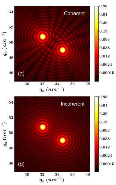
To illustrate this point, let us for instance consider the model system envisaged by LRPS made of two identical Pd cylinders with the upper one rotated by different angles around the common [hh0] axis. According to these authors “A WPPM analysis of the corresponding powder patterns shows that for tilt angles 1.5 ∘ coherence between the two half-cylinders is completely lost, so that powder diffraction “sees” completely separate (incoherently scattering) domains”. Considering now the same sample studied with X-ray coherent diffraction, this supposed “loss of coherence” is not observed. Figure 3 shows an example of large tilt angle (3 degrees) where clearly one can make the difference between the real diffraction pattern from the two cylinders [Fig.3(a)] and the one that would correspond to incoherent diffraction [Fig.3(b)].
Finally, let us mention that Fig.3(a) is only a slice of a three dimensional reciprocal space structure. From the measurement of this latter, associated with measurements around other reciprocal space points, an inversion method should provide the two cylinders structure including their relative orientation. This method was used recently to determine the structure of inversion domains in a Gallium Nitride nanowireLabat et al. (2015), a system which presents similarities with the one discussed here.
References
- Gailhanou and Roussel (2013) M. Gailhanou and J.-M. Roussel, “Displacement field of a screw dislocation in a Cu nanowire: An atomistic study,” Phys. Rev. B 88, 224101 (2013).
- Leonardi et al. (2015) A. Leonardi, S. Ryu, N. M. Pugno, and P. Scardi, “Eshelby twist and correlation effects in diffraction from nanocrystals,” Journal of Applied Physics 117, 164304 (2015).
- Eshelby (1953) J. D. Eshelby, “Screw dislocations in thin rods,” J.Appl.Phys. 24, 176 (1953).
- Hirth and Lothe (1982) J. Hirth and J. Lothe, Theory of dislocations, 2nd ed. (John Wiley and sons, 1982).
- Roussel and Gailhanou (2015) J.-M. Roussel and M. Gailhanou, “Stability of a screw dislocation in a copper nanowire,” Phys. Rev. Lett. 115, 075503 (2015).
- Labat et al. (2015) S. Labat, M.-I. Richard, M. Dupraz, M. Gailhanou, G. Beutier, M. Verdier, F. Mastropietro, T. W. Cornelius, T. U. Schülli, J. Eymery, and O. Thomas, “Inversion domain boundaries in GaN wires revealed by coherent bragg imaging,” ACS Nano 9, 9210–9216 (2015).