Backward Raman Amplification in the Long-wavelength Infrared
Abstract
The wealth of work in backward Raman amplification in plasma has focused on the extreme intensity limit, however backward Raman amplification may also provide an effective and practical mechanism for generating intense, broad bandwidth, long-wavelength infrared radiation (LWIR). An electromagnetic simulation coupled with a relativistic cold fluid plasma model is used to demonstrate the generation of picosecond pulses at a wavelength of with terawatt powers through backward Raman amplification. The effects of collisional damping, Landau damping, pump depletion, and wave breaking are examined, as well as the resulting design considerations for a LWIR Raman amplifier.
I Introduction
Chirped pulse amplification has provided access to intense, few cycle, near-infrared laser pulses for the last 30 years Strickland and Mourou (1985). It has been proposed that backward Raman amplification could provide similar access to the multipetawatt Trines et al. (2011) or even exawatt regime Malkin et al. (1999, 2000a). While experiments have yet to reach the multipetawatt regime Yampolsky et al. (2008); Yampolsky and Fisch (2011); Turnbull et al. (2012a, b); Wu et al. (2016); Ping et al. (2004); Cheng et al. (2005); Ren et al. (2008), we propose that backward Raman amplification could be a practical source of long-wavelength infrared radiation (LWIR) with terawatt peak powers.
The development of terawatt power pulses in the long-wavelength infrared is being driven by strong-field science, including advanced proton acceleration Palmer et al. (2011), high harmonic generation Popmintchev et al. (2012), mid-infrared supercontinuum generation Pigeon (2014); Pigeon et al. (2015), and nonlinear optics Mitrofanov et al. (2015).
There are several paths to high power LWIR: optical parametric amplification (OPA), difference-frequency generation (DFG), optical rectification (OR), and lasing using \ceCO2. In principle, the Manley-Rowe relations limit the conversion efficiency to the ratio of the photon energies , about 10%. In practice, the conversion efficiency is an order of magnitude less, for example: optical parametric amplification becomes inefficient due to absorption Voronin et al. (2016) and group-velocity mismatch Cerullo and De Silvestri (2003); difference-frequency generation is limited by phase-matching and optical nonlinearities Sell et al. (2008); and optical rectification is limited because it relies on the pump’s spectral wings Sell et al. (2008). As a result, frequency down-conversion from the near-infrared to LWIR is inherently inefficient.
Existing high power \ceCO2 amplifiers can create picosecond pulses with joules of energy Polyanskiy et al. (2011); Pigeon et al. (2015) at wavelengths of and . However, these amplifiers require a combination of large high pressure systems, expensive oxygen isotopes, and a high power seed pulse to sufficiently broaden the \ceCO2 gain spectrum for the generation of picosecond pulses. Furthermore, high gas pressure severely limits the system’s repetition rate. If sufficient broadening is not achieved, these systems create pulse trains instead of individual pulses. Two attempts have been made to overcome the bandwidth limitations of \ceCO2, one used the negative group velocity dispersion in \ceGaAs with a beatwave to compress \ceCO2 laser pulse trains Pigeon et al. (2015), and the other by the combination of self-chirping and a conventional dispersive compressor Pogorelsky et al. (2015).
This suggests that a compact wavelength source capable of terawatt powers and picosecond durations would be a key scientific and technological development. Plasma-based, backward Raman amplification can provide the bandwidth that is difficult to achieve in a \ceCO2 amplifier. This mechanism is self-phase-matched, and furthermore, optical nonlinearities in plasmas are weaker than in crystals. Additionally, the pumping \ceCO2 laser can be narrow-band, which removes the need for operation at high pressure, and in turn, improves the prospects for high repetition rate operation.
In backward Raman amplification, a backward propagating seed pulse, with frequency and wavenumber , stimulates the coherent backscattering of a forward propagating pump pulse from a plasma (Langmuir) wave . This enhances the plasma wave and further drives the energy from the pump to seed waves leading to exponential growth in the seed energy until pump depletion or another saturation mechanism occurs Kruer (1988).
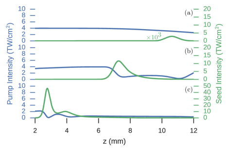
This process is illustrated by the simulation results of FIG. 1. The pump pulse (blue) is moving in the forward direction (left-to-right) while the seed pulse (green) is moving backwards (right-to-left). A uniform plasma covers the entire region. Both, the pump and seed are linearly polarized. The seed pulse is injected once the pump pulse is overlapping the plasma, as shown in FIG. 1(a). The initial seed pulse has a full width at half maximum (FWHM) duration of and intensity of . The seed pulse grows exponentially at the small-signal gain rate for Raman backscattering , where is the pump normalized vector potential, is the pump frequency, is the plasma frequency, is the pump wave length, is the pump intensity, and is the plasma density Kruer (1988). The results of exponential growth can be seen in FIG. 1(a) as the seed intensity increases by a factor of after entering the plasma with a peak intensity of . This corresponds to an approximate gain rate of . During the exponential growth regime, the seed pulse duration will lengthen, reaching a maximum duration of in this example. This is the result of enhanced backscatter due to a build up in the plasma wave at the tail of the seed pulse. Figure 1(b) shows when the seed becomes sufficiently intense to deplete the pump. At this point, the seed is operating in the pump-depletion regime Malkin et al. (1999). The leading edge of the seed is backscattering enough of the pump that it shadows the trailing edge of the seed. This results in temporal gain compression and can be seen in FIG. 1(b) and 1(c), with seed durations of and , respectively. Figure 1(c) shows that pump depletion continues. The seed intensity grows roughly linearly with propagation distance as it sweeps up the pump energy.
There is an existing body of literature on plasma-based backward Raman amplification. Three dimensional particle-in-cell simulations have shown power pulses being generated by backward Raman amplification at wavelengths of and Trines et al. (2011) but subsequent work suggests this is an overestimate Toroker et al. (2014); Edwards et al. (2015). Experimentally, the observed peak output powers are in the range of with efficiencies of for a pump wavelength of Ren et al. (2007, 2008). Previous work Malkin et al. (2000a) mentioned the possibility of scaling to the wavelength but for parameters where the initial seed intensity was equal to the pump intensity. While this is feasible for near-infrared or visible wavelengths, it is not for LWIR. This makes the exponential growth regime critical to the final seed output.
II Design Considerations for the Long-wavelength Infrared Regime
Without high power seed sources at wavelengths of , the seed must make use of both the small signal gain regime and depletion regime for backward Raman amplification to be effective. The small signal gain regime is required in order to get the seed into the depletion regime, at which point a significant fraction of the pump energy can be transfered to the seed pulse.
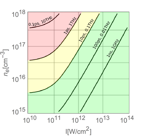
The pump intensity and plasma density are major design considerations as both directly influence the gain rate, wave breaking, and other instabilities. Figure 2(a) shows a contour plot illustrating various design limitations in the plasma density and pump intensity parameter space. The gray lines show the time-independent backward Raman gain length, the length over which the seed field strength will increase by a factor of , given by , where is the collisionless gain rate. The black lines show the effect of electron-ion collisions on the gain length , where is the collisional gain rate given by Eq. (4) Kruer (1988); Strozzi (2005). The electron-ion collision rate depends on the plasma temperature and ponderomotive energy with a functional form approximated by . While time-dependent effects are important Malkin et al. (1999), the time-independent gain rate is illustrative for understanding the trade-offs in pump intensity and plasma density.
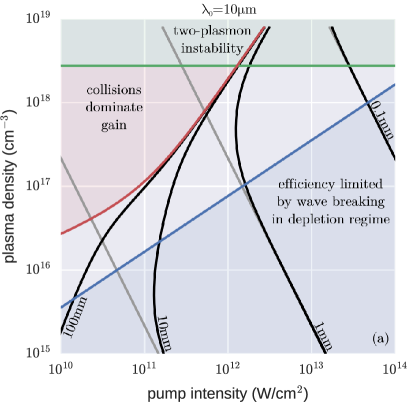
Shorter gain lengths are produced with higher pump intensities and plasma densities because both enhance the plasma wave. At high plasma density, electron-ion collisions () will damp out the plasma wave faster than growth from backward Raman amplification () Kruer (1988); Strozzi (2005). The difference in the collisional and collisionless gain lengths (black and gray curves of FIG. 2(a)) show where collisional damping becomes important. The red lines mark the instability threshold where the gain is zero due to collisional damping and is given by , where is the energy damping rate of the electromagnetic wave (see Appendix A) Kruer (1988). The isocontours of the collisional gain length (black curve) compress against the boundary where collisions dominate gain (red curve) because as the gain approaches zero, the gain length goes to infinity. Additionally, the collisional damping is suppressed at pump intensities where the ponderomotive energy is greater than the plasma temperature . This can be observed in FIG. 2(a) where the red line changes slope.
The green line at quarter critical density marks where the two-plasmon decay occurs and where the Raman instability becomes absolute. This sets a hard upper bound on the possible plasma density, otherwise the pump would be rapidly absorbed by the plasma. Typically, other instabilities (forward Raman, parasitic backward Raman, or filamentation) will dominate at plasma densities below quarter critical Trines et al. (2011).
Plasma wave breaking can limit efficient depletion of the pump. During depletion, each pump photon is stimulated to scatter into an additional seed photon and plasmon. The plasma wave, however, has a maximum energy density that it can support Kruer (1988), in other words, a maximum plasmon density. Therefore, when the maximum plasmon density has been reached, the seed growth is stunted. The blue curve of FIG. 2(a) marks the largest pump intensity that the plasma can support during 100% depletion Malkin and Fisch (2014). The pump intensity should be below Malkin and Fisch (2014) to avoid wave breaking. Plasma wave breaking does not affect the small signal growth of the seed pulse, but it will change the overall efficiency of the growth when the seed is in the depletion regime Malkin et al. (1999). Therefore this is a soft limitation and there is evidence that some wave breaking is preferable as it can limit energy growth in the tail of the seed pulseMalkin et al. (1999).
Within these constraints, we can see the gain length varies from to . There are, however, experimental limitations to realizing a particular plasma length, density, and uniformity. In particular, available sources generate long-wavelength infrared pulses with microjoules of energy, requiring four to five e-foldings in the linear growth regime. The need of using both the linear and nonlinear regimes is distinct from previous studies which focused primarily on near-infrared or visible light where intense, short pulses for seeding are readily available.
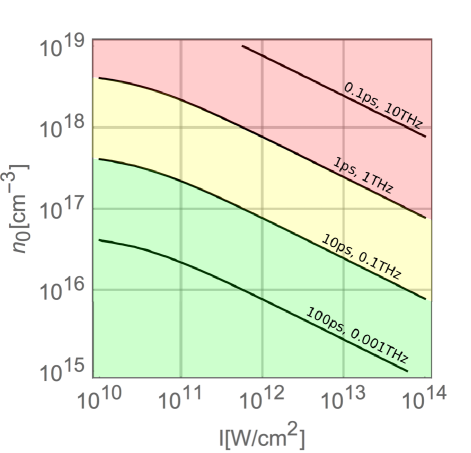
The parameter space for can be contrasted with FIG. 2(b) which shows the gain length as a function of pump intensity and plasma density for . It is clear that the operating window is smaller for , but this is less significant because there are not the same technological limitations on seed pulse generation.
In summary, this motivates using laser pump intensities of around and plasma densities around in order to avoid collisional damping, wave breaking, and have a sufficiently small gain length. We note that the conculsions hold for an electron temperature of . A lower pump intensity is possible for higher electron temperatures.
III Numerical Results
Motivated by the regime described above, we carried out one and two-dimensional simulations using the turboWAVE framework, which couples a finite-difference time-domain (FDTD) electromagnetic solver with a collisional, relativistic cold fluid plasma model Gordon et al. (2000). The simulation domain consists of several sections in the following order; a “vacuum” section, an up ramp, a uniform plasma section, a down ramp, and a final “vacuum” section. The uniform plasma section has a density and length . The “vacuum” sections have an electron density . The “vacuum” and ramp sections are all long. The electron-ion collision model requires a constant plasma temperature which is set at .
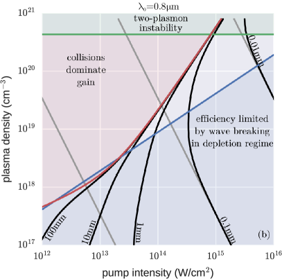
A scaling of the pump intensity for fixed plasma density was carried out to illustrate the effects of collisional damping, the exponential gain regime, and the depletion regime on final intensity and FWHM duration of the seed pulse. These can be seen in FIG. 3. For this specific set of simulations, the plasma density is , the plasma frequency is , the grid size is , and the time step is .
The pump pulse () enters the left side of the simulation domain at . The initial seed pulse () enters the right side of the constant plasma density region as the pump pulse at the left side reaches half its peak intensity. The seed pulse frequency was chosen to be on resonance for the Raman instability . The initial seed pulse’s FWHM duration is with contained within. The initial fluence was chosen so that with a cross-section, the initial seed pulse would have energies. The plasma length is . The pump pulse FWHM duration is , which corresponds to twice the plasma length . Field values were recorded at the simulation boundaries. Spectral box filters from around the pump and seed frequencies were used to extract individual field envelopes and intensity profiles.
Figure 3 shows the dependence of the amplified seed on pump intensity with and without electron-ion collisions, the green and blue curves, respectively. At intensities below , there is no significant gain in the seed pulse because the gain length is comparable to the plasma length, as seen in FIG. 2(a). As the pump intensity is increased from to just below , the seed intensity in the collisionless plasma grows exponentially with pump intensity. This means that an increase in the pump intensity allows the seed to undergo additional e-foldings within the fixed plasma length. This stops at just below , where the seed begins growing more slowly with pump intensity. The seed pulse has grown sufficiently intense that it is beginning to deplete the pump. Similar to what occurs in FIG. 1, once the seed pulse begins depleting the pump, the rate of increase in the seed intensity is no longer exponential, but roughly linear with the encountered pump fluence. For fixed plasma length, this suggests that the seed will grow roughly linearly with pump intensity. The rate of increase in FIG. 3 is faster than linear, because a higher pump intensity shortens the length needed for the seed to exponentiate and reach depletion. This increases the length over which the seed can deplete and, hence, the seed grows faster than linear with pump intensity. For a pump intensity of , the maximum seed intensity reached with a duration of . For a cross-sectional area, this corresponds to a peak power of , energy of , and amplification factor of . Further increase in pump intensity may be beneficial, but cannot be simulated using a fluid model due to wave breaking.
The temporal dynamics of the seed pulse also show the exponential growth and depletion regimes. When the gain length is longer than the plasma length, the seed’s final duration is equal to the initial duration, as seen in the first three points of FIG. 3(b). During the small signal gain regime, the point of maximal growth sweeps backwards at Malkin et al. (2000b). Essentially, the leading edge of the seed is driving a plasma wave causing increased backscatter later in the seed pulse. This can be seen most clearly in the collisionless plasma where seed durations of are observed. When collisions are included, the seed duration still grows during the linear regime but only at higher pump intensities where the electron-ion collision rate is less important. Once the seed begins depleting the pump, the seed duration rapidly decreases. What is occurring is not compression of the seed energy, but amplification in the seed’s leading edge, namely temporal gain compression. Pulse durations as short as are reached. This is shorter than the - pulses that are typically created in high power \ceCO2 lasers Pigeon (2014); Pogorelsky et al. (2015). Previous work has shown that some degree of wave breaking is beneficial. When wave breaking occurs after the peak of the seed pulse has passed, it can suppress the growth in trailing pulses, such as those seen in FIG. 1(c) Malkin et al. (1999).
Figure 4 plots the final seed intensity and pulse duration as a function of the initial seed duration, for a fixed fluence. The pump intensity is and all other parameters are the same as FIG. 3.
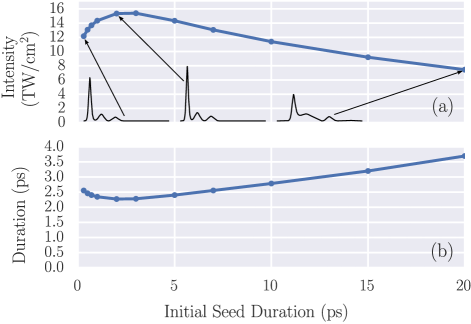
There is a weak dependence of the seed’s final intensity and duration on its initial duration. This suggests that the initial seed pulse duration is not a critical design parameter.
The intensity maximum in FIG. 4(a) can be understood from the dynamics of the small signal gain. The point of maximal gain sweeps backward at half the speed of light Malkin et al. (2000b). If the seed it too short, the point of maximal gain will pass over it and amplify its weak tail. This can seen in the leftmost inset intensity profile of FIG. 4(a). If the seed is too long, the head of the seed will amplify to the depletion regime before the tail. In this case, the pulse would have reached depletion sooner had the pulse been shorter. This can seen in the rightmost inset intensity profile of FIG. 4(a), because energy was transfered to the long, secondary pulse during exponential growth, delaying the onset of pump depletion and reducing the time for the short, primary pulse to grow.
Two-dimensional turboWAVE simulation results are shown in FIG. 5. This simulation is similar to those previously shown with several differences. The initial seed intensity and duration are and . The pump and seed’s initial field spot sizes are . The pump intensity is . The geometry is planar. The longitudinal and transverse spatial coordinates are and , respectively. Along the longitudinal direction, the plasma is constructed the same as the one-dimensional simulations. The plasma profile in the transverse direction is uniform with periodic boundary conditions. The simulation domain had 83328 and 64 cells in the z- and x-directions, respectively. The cell size is and in the z- and x-directions, respectively.
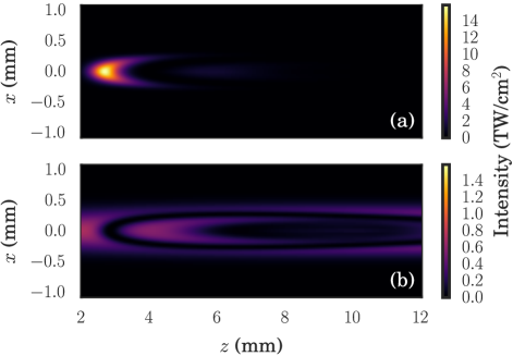
The depletion of the pump can be seen in FIG. 5(b). The seed intensity has increased by a factor of 360. The seed has a smaller spot size due to gain focusing. This shows that comparable results are possible in one- and two-dimensional simulations. The transverse grid size is too large to resolve plasma perturbations needed to drive the filamentation instability. Further investigation is needed to determine the importance of that effect.
IV Numerical Limitations
Two modeling limitations have been observed when simulating backward Raman amplification. First, the fluid simulations are limited by wave breaking of the plasma which occurs for pump intensities around at wavelengths of and densities of . The most promising cases for amplification tend to occur when the pump intensity is at or above the wave breaking limit, as suggested by FIG. 2. Specifically, this occurred for pump intensities of . The pump pulse alone will not drive a significant plasma wave by itself. As the seed is amplified, it beats with the pump and drives the plasma wave to break. Fundamentally, this limits the maximum seed intensities that are possible to reach in fluid simulations at a given pump intensity.
Particle-in-cell (PIC) simulations offer the ability to model the amplification process in the regime above plasma wave breaking. Extensive PIC simulations have been carried out and show quantitative agreement with the collisionless fluid model. However, when the number of potential e-foldings is sufficiently large, to , parasitic Raman backscatter competes with the amplification process and limits growth. The seeding of the parasitic process is several orders of magnitude larger in the PIC versus fluid simulations. This limits the use of a PIC plasma model for this problem because it is of practical importance to start with an initially weak seed pulse. Detuning the interaction with a spatially varying plasma density Malkin et al. (2000b) may suppress amplification of noise and make PIC simulations for these parameters more feasible, but the need of multiple e-foldings for the seed to reach depletion makes the detuning technique more challenging.
V Conclusion
Simulations have demonstrated that backward Raman amplification can compress and amplify LWIR pulses. The turboWAVE framework has been used to carry out one- and two-dimensional FDTD electromagnetic simulations coupled to a relativistic cold fluid plasma model with electron-ion collisions. Using a pump pulse that could be generated by a \ceCO2 laser, it was shown that a seed pulse at could be amplified to and compressed to a duration of . When compared to the initial pump pulse, the final seed pulse is 10 times more intense and 50 times shorter. The final seed amplification is weakly dependent on the initial seed duration, which is promising as sources are limited.
Limitations in available long wavelength infrared sources motivated the use of both the linear and nonlinear growth regimes. For large plasma densities, collisional damping can eliminate growth unless pump intensities are sufficiently intense to compensate for, or suppress, damping. This is particularly important during the linear growth regime. In the depletion regime, plasma wave breaking provides a soft upper limit on the pump intensity by limiting the depletion efficiency. At large plasma densities and pump intensities, two-plasmon decay or absolute Raman will deplete the pump, but a more detailed analysis of the other limiting instabilities is needed. The ultimate limits on efficiency could not be determined because of numerical difficulties. Future work should include a collisional kinetic model in which the noise source can be controlled and a study of the importance of plasma length and temperature.
Appendix A Temporal Weak Coupling Gain
As derived elsewhere Strozzi (2005); Kruer (1988), the Raman backscattering dispersion relation for the plasma density perturbations with frequency and wavenumber is
| (1) |
where the Bohm-Gross frequency is , the electron thermal velocity is , the electron temperature is , the energy damping rate of the electron plasma wave , the pump frequency and wavenumber are , the energy damping rate of the electromagnetic wave (inverse-bremsstrahlung) is , and the quiver velocity is , where the pump vector potential is Kruer (1988).
The scattered electromagnetic wave should have a frequency . A frequency detuning of from the resonant frequency defines the scattered wave frequency . The plasma wave should have approximately the Bohm-Gross frequency. We will define the frequency with a real frequency shift of for detuning and a complex shift of for gain and collisional damping, that is, . After making the approximation that the dispersion relation reduces to
| (2) |
where the resonant, collisionless gain rate is
| (3) |
The complex frequency shift of the plasma density perturbation is
| (4) |
In the limit of no collisions and resonant Raman , . In the limit of resonant Raman but no Raman gain , then the frequency shift just accounts for the collisional damping of the plasma wave . In the limit of no Raman gain and no collisions , there is no induced frequency shift .
If the interaction is resonant, , then we get the following condition for an instability Kruer (1988). If , then which says that an instability only exists for . The power spectrum after an interaction time of , will be proportional to . In the limit that the detuning is much less than the resonant, collisionless gain rate, the FWHM duration of the seed intensity will be approximately . This suggests that during the linear growth regime, the pulse durations will grow with time due to gain narrowing, and shorten with increased gain rate due to a larger gain bandwidth.
Appendix B Collisional Damping
Collisional damping can play a significant role in backward Raman amplification depending on the pump intensity and plasma density.
The intensity-dependent electron-ion collision rate is given by , where the zero intensity rate is , the quiver velocity is , the thermal velocity is , , and the functions are modified Bessel functions of the first kind. The electron charge and mass are and . The Coulomb logarithm is and ionization degree is . The electron-ion collision rate is proportional to the plasma density and inversely proportional to the electron velocity cubed. The thermal and quiver velocity play a role in the overall collision rate, as can be seen by and , respectively. This has been investigated in detail Catto and Speziale (1977). As laser intensity increases and the quiver velocity becomes greater than the thermal velocity, the collision rate begins to decrease.
The effect of laser polarization on the electron-ion collision rate was estimated to not cause a difference larger than a factor of in the rate Catto and Speziale (1977).
Electron-neutral collisions are not considered in the simulations but are a significant consideration if the plasma is not fully ionized. The collision rate is given by where is the neutral density, Huba (2004). To include the increased rate of collisions due to electron quiver, the following substitution can be used . An approximate expression for the electron neutral collision rate is . Figure 7 shows contours of constant electron-neutral collision rate. Generation of picosecond duration pulses requires the use of pump intensities and neutral densities where the collisional damping is slower than the seed pulse. As seen in FIG. 7, this means neutral densities below would be feasible.
Finally, previous work found evidence of Landau damping Trines et al. (2011) but it saturated quickly and was insignificant. The damping rate can be estimated by Fitzpatrick (2014), where the characteristic plasma wave wavenumber is and the Debye length is . For a pump wavelength of , plasma density of , temperature of , and , the damping rate relative to the plasma frequency is insignificant. At lower densities of , the relative damping rate is and could warrant further consideration.
The units in this section are cgs-Gaussian unless otherwise stated.
Acknowledgements.
We would like to acknowledge A. Stamm and N. Fisch for fruitful discussions and J. Rajkowski for careful proofreading. Data post-processing and plotting was carried out using the following Python packages; seabornWaskom et al. (2016), pandas McKinney (2010), numpyVan Der Walt et al. (2011), and mpmathJohansson et al. (2013). This work has been supported by the U.S. Naval Research Laboratory’s Karle Fellowship. Resources of the Department of Defense High Performance Computing and Modernization Program (HPCMP) were used in this work.References
- Strickland and Mourou (1985) D. Strickland and G. Mourou, Optics Communications 56, 219 (1985).
- Trines et al. (2011) R. Trines, F. Fiuza, R. Bingham, R. Fonseca, L. Silva, R. Cairns, and P. Norreys, Nature Physics 7, 87 (2011).
- Malkin et al. (1999) V. Malkin, G. Shvets, and N. Fisch, Physical Review Letters 82, 4448 (1999).
- Malkin et al. (2000a) V. Malkin, G. Shvets, and N. Fisch, Physics of Plasmas (1994-present) 7, 2232 (2000a).
- Yampolsky et al. (2008) N. Yampolsky, N. Fisch, V. Malkin, E. Valeo, R. Lindberg, J. Wurtele, J. Ren, S. Li, A. Morozov, and S. Suckewer, Physics of Plasmas (1994-present) 15, 113104 (2008).
- Yampolsky and Fisch (2011) N. A. Yampolsky and N. J. Fisch, Physics of Plasmas (1994-present) 18, 056711 (2011).
- Turnbull et al. (2012a) D. Turnbull, S. Li, A. Morozov, and S. Suckewer, Physics of Plasmas (1994-present) 19, 083109 (2012a).
- Turnbull et al. (2012b) D. Turnbull, S. Li, A. Morozov, and S. Suckewer, Physics of Plasmas (1994-present) 19, 073103 (2012b).
- Wu et al. (2016) Z. Wu, K. Zhou, X. Zheng, X. Wei, Q. Zhu, J. Su, N. Xie, Z. Jiao, H. Peng, X. Wang, et al., Laser Physics Letters 13, 105301 (2016).
- Ping et al. (2004) Y. Ping, W. Cheng, S. Suckewer, D. S. Clark, and N. J. Fisch, Physical review letters 92, 175007 (2004).
- Cheng et al. (2005) W. Cheng, Y. Avitzour, Y. Ping, S. Suckewer, N. J. Fisch, M. S. Hur, and J. S. Wurtele, Physical review letters 94, 045003 (2005).
- Ren et al. (2008) J. Ren, S. Li, A. Morozov, S. Suckewer, N. Yampolsky, V. Malkin, and N. Fisch, Physics of Plasmas (1994-present) 15, 056702 (2008).
- Palmer et al. (2011) C. A. J. Palmer, N. P. Dover, I. Pogorelsky, M. Babzien, G. I. Dudnikova, M. Ispiriyan, M. N. Polyanskiy, J. Schreiber, P. Shkolnikov, V. Yakimenko, and Z. Najmudin, Phys. Rev. Lett. 106, 014801 (2011).
- Popmintchev et al. (2012) T. Popmintchev, M.-C. Chen, D. Popmintchev, P. Arpin, S. Brown, S. Ališauskas, G. Andriukaitis, T. Balčiunas, O. D. Mücke, A. Pugzlys, et al., Science 336, 1287 (2012).
- Pigeon (2014) J. Pigeon, Generation of ultra-broadband, mid-IR radiation in GaAs pumped by picosecond 10 m laser pulses, Master’s thesis, UCLA: Electrical Engineering (2014).
- Pigeon et al. (2015) J. Pigeon, S. Y. Tochitsky, and C. Joshi, Optics letters 40, 5730 (2015).
- Mitrofanov et al. (2015) A. Mitrofanov, A. Voronin, D. Sidorov-Biryukov, A. Pugžlys, E. Stepanov, G. Andriukaitis, T. Flöry, S. Ališauskas, A. Fedotov, A. Baltuška, et al., Scientific Reports 5 (2015), 10.1038/srep08368.
- Voronin et al. (2016) A. Voronin, A. Lanin, and A. Zheltikov, Optics Express 24, 23207 (2016).
- Cerullo and De Silvestri (2003) G. Cerullo and S. De Silvestri, Review of scientific instruments 74, 1 (2003).
- Sell et al. (2008) A. Sell, A. Leitenstorfer, and R. Huber, Optics Letters 33, 2767 (2008).
- Polyanskiy et al. (2011) M. N. Polyanskiy, I. V. Pogorelsky, and V. Yakimenko, Optics Express 19, 7717 (2011).
- Pogorelsky et al. (2015) I. V. Pogorelsky, M. Babzien, I. Ben-Zvi, J. Skaritka, and M. N. Polyanskiy, Nuclear Instruments and Methods in Physics Research Section A: Accelerators, Spectrometers, Detectors and Associated Equipment (2015), 10.1016/j.nima.2015.11.126.
- Kruer (1988) W. L. Kruer, The physics of laser plasma interactions (Reading, MA (US); Addison-Wesley Publishing Co., 1988).
- Toroker et al. (2014) Z. Toroker, V. Malkin, and N. Fisch, Physics of Plasmas (1994-present) 21, 113110 (2014).
- Edwards et al. (2015) M. R. Edwards, Z. Toroker, J. M. Mikhailova, and N. J. Fisch, Physics of Plasmas (1994-present) 22, 074501 (2015).
- Ren et al. (2007) J. Ren, W. Cheng, S. Li, and S. Suckewer, Nature Physics 3, 732 (2007).
- Strozzi (2005) D. J. Strozzi, Vlasov simulations of kinetic enhancement of Raman backscatter in laser fusion plasmas, Ph.D. thesis, Massachusetts Institute of Technology (2005).
- Malkin and Fisch (2014) V. Malkin and N. Fisch, The European Physical Journal Special Topics 223, 1157 (2014).
- Gordon et al. (2000) D. F. Gordon, W. Mori, and T. M. Antonsen, IEEE Transactions on Plasma Science 28, 1135 (2000).
- Malkin et al. (2000b) V. Malkin, G. Shvets, and N. Fisch, Physical Review Letters 84, 1208 (2000b).
- Catto and Speziale (1977) P. Catto and T. Speziale, Physics of Fluids (1958-1988) 20, 167 (1977).
- Huba (2004) J. D. Huba, NRL: Plasma formulary, Tech. Rep. (DTIC Document, 2004).
- Fitzpatrick (2014) R. Fitzpatrick, Plasma physics: an introduction (CRC Press, 2014).
- Waskom et al. (2016) M. Waskom, O. Botvinnik, drewokane, P. Hobson, Y. Halchenko, S. Lukauskas, J. Warmenhoven, J. B. Cole, S. Hoyer, J. Vanderplas, and et al., “seaborn: v0.7.0 (january 2016),” (2016).
- McKinney (2010) W. McKinney, in Proceedings of the 9th Python in Science Conference, edited by S. van der Walt and J. Millman (2010) pp. 51 – 56.
- Van Der Walt et al. (2011) S. Van Der Walt, S. C. Colbert, and G. Varoquaux, Computing in Science & Engineering 13, 22 (2011).
- Johansson et al. (2013) F. Johansson et al., mpmath: a Python library for arbitrary-precision floating-point arithmetic (version 0.18) (2013), http://mpmath.org/.