Ultrafast photoionization and excitation of surface-plasmon-polaritons on diamond surfaces
Abstract
Ultrafast plasmonics of novel materials has emerged as a promising field of nanophotonics bringing new concepts for advanced optical applications. Ultrafast electronic photoexcitation of a diamond surface and subsequent surface plasmon-polaritons (SPPs) excitation are studied both theoretically and experimentally - for the first time. After photoexcitation on the rising edge of the pulse, transient surface metallization was found to occur for laser intensity near 18 TW/cm2 due to enhancement of the impact ionization rate; in this regime, the dielectric constant of the photoexcited diamond becomes negative in the trailing edge of the pulse thereby increasing the efficacy with which surface roughness leads to inhomogeneous energy absorption at the SPP wave-vector. These transient SPP waves imprint permanent fine and coarse surface ripples oriented perpendicularly to the laser polarization. The theoretical modeling is supported by the experiments on the generation of laser-induced periodic surface structure on diamond surface with normally incident 515-nm, 200-fs laser pulses. Sub-wavelength ( nm) and near wavelength ( nm) surface ripples oriented perpendicularly to the laser polarization emerged within the ablative craters with the increased number of laser shots; the spatial periods of the surface ripples decreased moderately with the increasing exposure. The comparison between experimental data and theoretical predictions demonstrates the role of transient changes of the dielectric permittivity of diamond during the initial stage of periodic surface ripple formation upon irradiation with ultrashort laser pulses.
I Introduction
Diamond is a material, exhibiting unique mechanical, thermal and electrical properties, as well as high electron and hole mobility Isberg2002 , promoting its high performance in microelectronic devices. At the same time, diamond is a basic ingredient in modern nanophotonics Aharonovich2014 ; Hausmann2012 . Due to its high refractive index in UV-VIS range, it is prospective material for all-dielectric Kuznetsov2016 and even hybrid metal-dielectric nano-photonic devices and circuits Ozkan1999 ; Pham2016 ; Ivanova2016 . Moreover, despite its dielectric character, similarly to silicon it can be promptly turned by intense ultrashort laser pulses into short-lived plasmonic state, becoming so-called ”virtual plasmonic material”, supporting photoexcitation and propagation of surface plasmon-polaritons (SPPs) Boltasseva2011 ; Kumar2013 ; Danilov2015 , for potential applications in ultrafast optical switching, spatial phase modulation and saturable absorption Boltasseva2011 , Alam2016 ; Jahani2016 ; west2010 ; Naik2013 . Meanwhile, experimental ultrafast SPP photoexcitation on diamond surfaces was not realized yet, even though their potential imprinting in surface relief in the form of polarization-dependent laser-induced periodical surface structures (LIPSS, surface ripples) was numerously evidenced Miyaji2008 ; Shinoda2009 ; Wu2003 . Such experimental studies were devoted to the design and fabrication of bio-sensors, employing the biocompatibility of the material, by ablative surface nanostructuring of its surface with high-intensity femtosecond (fs) laser pulses, assuring precise delivery of energy, while precluding collateral thermal effects. In the case of diamond, ultimate LIPSS periods of 100–125 nm on diamond-like carbon for 800-nm fs-laser pulses Miyaji2008 , or even 50-100 nm on thin diamond films for 248-nm fs-laser pulses Shinoda2009 (down to 30–40 nm on diamond-like carbon after irradiation with 266-nm femtosecond pulses) Wu2003 ; Yasumaru2003 were reported, empirically scaling as the normalized laser wavelength ( is the refractive index of diamond), similarly to other dielectrics Bonse2009 ; Gottmann2009 . However, despite some previous attempts Miyaji2008 ; Derrien2013 ; Miyazaki2005 , the underlying photoexcitation of diamond surface and SPP waves still remain unexplained.
Generally, spatial LIPSS periods are known to depend on the laser wavelength and the polarization of the laser electric field and the number of laser pulses Calvani2014 ; Sipe1983 ; Akhmanov1985_1 ; Huang2009_1 ; Varlamova2006 ; Huang2009_2 ; Bonse2010 ; Tsibidis2015 . The surface ripple period can be slightly less than , succeeding the in-plane weak interference of the incident transverse fs-laser wave and almost transverse surface polaritons Danilov2015 . These surface electromagnetic modes, residing along the light cone line on dispersion curves for the metallic or strongly photoexcited dielectric surface with its dielectric permittivity and its intact dielectric with its dielectric permittivity are photoexcited by the fs-laser pump pulse via its scattering on permanent or laser-induced (e.g., phase transition from diamond to glassy or diamond-like carbon phase) cumulative surface relief roughness Varlamova2006 ; Huang2009_2 ; Bonse2010 ; Tsibidis2015 , or prompt laser-induced ”optical roughness” Ionin2015 , if the condition ] is fulfilled Huang2009_1 ; Ionin2013 . Meanwhile, in the corresponding spectrally-narrow surface plasmon resonance, occurring for the photoexcited surface at ], the short-wavelength, longitudinal surface plasmons can similarly interfere with the incident wave or among themselves (for counter-propagating quasi-monochromatic surface plasmons), inducing surface ripples with periods much lower than ( /2, /6, ..) Huang2009_1 ; Borowiec2003 ; Golosov2011 ; Nathala2015 . Importantly, in the former case, the surface polariton-mediated, near-wavelength ripples are always oriented perpendicularly to (their wavevector ), while the fine nanoripples can be oriented in both ways, depending which – red or blue – shoulder of the surface plasmon resonance is involved Kudryashov2015 . Laser exposure (the number of incident pulses per spot, ) is known to influence LIPSS (both ripples and nanoripples Nathala2015 ) to much less extent, inducing about 30% reduction in their periods versus exposures, increasing to 102-103 Huang2009_2 ; Bonse2010 ; Tsibidis2015 . Other effects – angle of incidence/laser polarization Ionin2012 , intact dielectric Golosov2009 ; Ionin2014 ; Bashir2015 indicate some emerging possibilities in reduction of LIPSS periods, but should be explored in details yet. Meanwhile, nanoscale hydrodynamics instabilities of laser-induced surface melt were also considered and explored as an alternative to the diverse electromagnetic approaches Reif2011 ; Varlamova2013 ; Tsibidis2012 .
Since the prompt dielectric permittivity of the photoexcited surface appears to be crucial for excitation either near-wavelength surface polaritons, or sub-wavelength surface plasmons, prompt photoexcitation (photoionization) of diamond, directly affecting its dielectric permittivity, should be explored in details. There are numerous semi-empirical approaches to explain LIPSS formation e.g. Sipe1983 ; vanDriel1982 ; Bonse2005 ; Jia2005 ; Dufft2009 , corroborating the experimental evidence, but no genuine microscopic approach is invoked so far. The basic physical processes involve excitation of electron-hole pairs, often parameterized by Keldysh approximate formulas. Photoionization may produce highly energetic electrons that collisionally ionize the valence band and produce more electrons in the conduction band. The multiplication of carriers may cause optical breakdown of bulk diamond. The collective response of charge carriers screens out the laser electric field inside the bulk when the number density is sufficiently large. At some instant of time the bulk dielectric function may become negative at the laser wavelength, allowing excitation of SPP at the rough surface and LIPSS formation via the optical interference mechanism. The dielectric properties of the laser-irradiated material in most cases are parameterized with Drude model Huang2009_2 ; Golosov2011 ; Becker1988 ; Shimotsuma2003 ; Bonse2009 ; Christensen2009 , which combines the ground state response with the laser-induced free-carrier response. This model usually requires three free parameters – the number density of electron-hole pairs, the free-carrier effective mass and the Drude damping time, which are adjusted to fit experimental data. Ref. Reitze1992 ; Sokol2000 proposed more elaborate model for the optical dielectric function, which implements state- and band-filling effects, renormalization of the band structure and free-carrier response. The dielectric function of laser-excited silicon was studied from first principles using the time-dependent density functional theory (TDDFT) Sato2014 . A distinguishing feature in the linear response of the photoexcited silicon is a plasmon peak with large Drude damping time as short as fs, despite the neglect of collisional effects in the TDDFT simulation. The real part of dielectric function was well fitted by a Drude free-carrier response showing that is sensitive to the total number density of excited electrons and not to the detailed distribution of electron-hole pairs, while sensitivity to the nonequilibrium distribution of the phototexcited carriers manifests in the imaginary part of the dielectric constant. Subsequently, TDDFT was applied to study ablation of silica subjected to ultrashort laser pulses Sato2015 . The comparison between the estimated surface ablation threshold and the experimental data suggests a non-thermal mechanism in the laser ablation of silica by fs-laser pulses, furthermore theoretical ablative crater depths agree with the measured ones. The drawback of this approach is its limitation to very short laser-matter interaction timescales (less than 10 fs).
In the present paper, we present theoretical and experimental results for the laser ablation and LIPSS formation on diamond surfaces subjected to normally incident 515-nm, 200-fs laser pulses. Our theoretical modeling of LIPSS formation on diamond surfaces is based on numerical solution of the time-dependent Schrödinger equation (TDSE) in bulk diamond subjected to a single intense laser pulse. The theory describes the electron dynamics quantum mechanically in the single-active-electron approximation. Collisional de-excitation of the photoexcited carriers and subsequent impact ionization are treated within rate equation approach and an optical breakdown threshold is derived. Due to the contribution of the impact ionization the real part of the bulk dielectric constant of the irradiated diamond becomes negative in the trailing edge of the pulse resulting in plasma that is opaque to the incident radiation. The inhomogeneous energy deposition in the surface was modeled with the Sipe-Drude efficacy factor theory Dufft2009 ; Bonse2009 in terms of time-dependent dielectric function of free carriers. The applicability of this efficacy factor theory for LIPSS formation in laser-irradiated dielectrics was confirmed by numerical solutions of the Maxwell’s equations at statistically rough surfaces Skolski2012 . The paper is organized as follows. In Sec. II we present the theoretical approach to describe LIPSS formation on diamond surfaces. Sec. III presents results for the ablative craters that were experimentally produced on the surface of monocrystalline diamond by multiple femtosecond laser pulses and the subsequent emergence of fine and coarse surface ripples with the increasing number of laser shots. The thresholds for surface ablation and nano-structuring of diamond and their dependence on the superimposed pulse number are obtained. The experimental data for the observed surface ripple periods is consistently interpreted within the Sipe theory based on free-carrier Drude response of the laser-excited diamond. Sec. IV contains our main conclusions.
II Theoretical approach
II.1 Inhomogeneous energy deposition
In order to model theoretically LIPSS formation in femtosecond-laser-excited diamond, we apply the ab initio theory developed by Sipe Sipe1983 . In this picture, the laser beam is incident on a rough surface, the (permanent or laser-induced) roughness is assumed to be confined within a surface region (selvedge) of thickness much smaller than the laser wavelength . The optically-induced polarization in the selvedge generates surface-scattered waves that interfere with the refracted laser beam leading to inhomogeneous energy deposition into the surface. The inhomogeneous energy absorption can be described by the function
| (1) |
where is the component of the laser propagation wave vector parallel to the surface, is a measure of surface roughness at wave-vector and is an efficacy factor describing the contribution to the energy absorption at the LIPSS wave vector . The prediction of Eq.1 is valid if the selvedge thickness is small compared to the LIPSS period, i.e. should be satisfied. The efficacy factor essentially incorporates the modification of the surface morphology and the variation of the dielectric constant of the photoexcited diamond. For normally incident s-polarized laser pulse with , the efficacy factor (as a function of the normalized wave-number ) can be written as with
| (2) |
where the response functions and
| (3) |
are given in terms of the transient bulk dielectric function (cf. Sec. Optical properties), and , the Fresnel transmission coefficient in the absence of the selvedge, the effective transverse susceptibility function , the surface roughness characterized by shape and filling factors, and the shape functions . When , the response function exhibits small kinks near the light line , in contrast exhibits sharp resonance structure due to the excitation of surface plasmons and diverges at the (complex) SPP wave-number .
II.2 Photoexcitation
Photoexcitation and the dielectric response of laser-irradiated diamond are treated in independent particle approximation based on the 3D TDSE. In a long-wavelength approximation the light pulse is represented by a spatially uniform time-dependent electric field and velocity gauge is used throughout the calculations Lagomarsino2016 . The static bulk band structure is represented by the lowest 4 valence bands and 16 unoccupied conduction bands. The Brillouin zone was sampled by a Monte Carlo method using 2000 randomly generated -points. The time step for integration of the equations of motion was a.u.
The static band structure along the -line is shown in Fig.1. Carrier excitation occurs through the direct gap at the point, however excitation into higher lying conduction bands is also a relevant process for the considered laser intensity range I[1,50] TW/cm2.

During the irradiation of the diamond surface with pulsed 200 fs-laser, the total number of electrons generated into the conduction band is given by a Brillouin zone integral
| (4) |
where is the occupation number of the -th conduction band and is the crystal momentum. The electronic excitation energy per unit cell is given by
| (5) |
where are the time-evolved Bloch orbitals of valence electrons and is the ground-state energy. The time evolution of the free-electron density is shown in Fig. 2a, for linearly polarized electric field along the (1,1,1) direction with intensity 30 TW/cm2. Carrier generation occurs efficiently prior to the peak of the pulse. Transient charge density oscillations following the laser period are due to quiver motion of free electrons in the electric field. An electron-hole plasma (EHP) with number density exceeding is established shortly after the peak intensity. The cycle-averaged photoelectron yield, shown in Fig. 2b, is a slowly varying function of time. Carrier generation on the rising edge of the pulse competes with recombination on the trailing edge of the pulse to determine the final photoionization yield. Recombination of carriers becomes unlikely with the increased laser intensity, cf. also Fig. 2b. The cycle averaged electron yield includes contributions due to creation of real as well as virtual electron-hole pairs. Since adiabatic evolution does not produce any real excitation of the crystal, the carrier density should be calculated with respect to adiabatically evolved ground state orbitals that are obtained from the static Bloch orbitals with shifted crystal momentum , i.e. , where the adiabatic density is
| (6) |
and are the lattice-periodic Bloch states. The number density of photoexcited carriers is shown in Fig. 2c. It can be seen that discarding contributions of virtually excited electron-hole pairs leads to reduction in the number density by an order magnitude near the peak of the pulse.
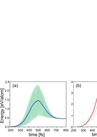
The electronic excitation energy is shown in Fig. 3(a) for laser intensity 30 TW/cm2. The temporal variation of the cycle-averaged energy gain follows closely the envelope of the laser pulse during the first half of the driving pulse and reaches 1.5 eV/atom at the peak of the pulse that is small as compared to the cohesive energy of diamond 7.37 eV/atom. After the pulse peak, electron-hole pairs recombine by transferring part of their energy back to the radiation field. Energy exchange is not completely reversible since the time delay in restoration of equilibrium gives rise to a net energy gain of 0.5 eV per carbon atom after the end of the pulse. The deposited energy increases steadily with the increase of the intensity, i.e. for I50 TW/cm2, it reaches 2 eV/atom. Since this excitation energy is still lower than the diamond cohesive energy, Fig. 3(b) shows that ablation threshold is not reached up to I50 TW/cm2.
II.3 Impact ionization and optical breakdown threshold
For the 200fs pulse duration and intensities lower than 50 TW/cm the electron density produced by photoionization is below the critical one. That suggests that impact ionization is the relevant process that determines the optical breakdown threshold. In Fig.4 (a-c) we plot the density of conduction states after the end of the pulse. It is seen that the laser has created electron-hole pairs with well-defined energies. This non-thermal distribution relaxes towards the equilibrium Fermi-Dirac distribution on a time scale ranging over few tens of a femtoseconds to a picosecond Yoffa1980 ; Fann1992 without changing the electron number density. Photoelectrons are excited into the lowest conduction band across the direct gap (with energies 2 eV above the conduction band minimum) and substantial fraction of carriers occupy higher lying conduction bands with energy above threshold for impact ionization (specified by the indirect gap 5.4 eV). These highly energetic electrons may collisionally de-excite to lower energy states and their excess energy is spent to promote valence electrons into the conduction band.

We further assume that the time evolution of the electron density is governed by a rate equation Apostolova2000 ; Stewart1995
| (7) |
including carrier generation and recombination rates supplemented by an intensity-dependent impact ionization rate obtained as a weighted-average of the field-free ionization rate
| (8) |
here is the density of conduction states after the end of the pulse (cf. Fig.4a-c),
| (9) |
is the energy-dependent impact ionization rate for diamond, is the threshold for impact ionization (5.42 eV) and Watanabe2004 .
In contrast to the standard perturbative result based on Keldysh theory valid for monochromatic laser radiation the calculated carrier generation and recombination rates shown in Fig.5a do not follow the temporal profile of the laser pulse. This result suggests that the pulse shape and pulse duration are relevant control parameters for non-adiabatic electron dynamics in the laser irradiated diamond. The key features are generation of dense plasma 50fs prior to the pulse peak and subsequent laser-induced recombination of electron-hole pairs in the trailing edge of the pulse.
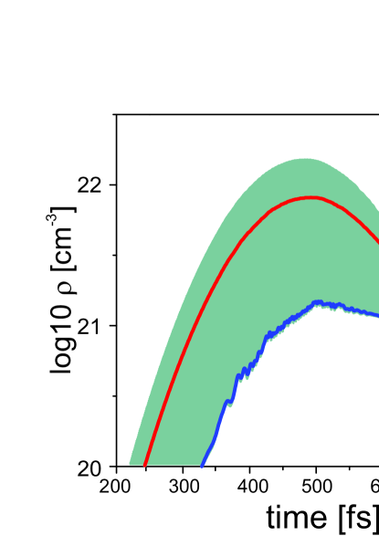
Fig.5b shows the impact ionization rate that depends in highly non-linear way on the laser intensity. This non-linear and non-monotonic intensity-dependence reflects the population of higher-lying conduction bands (cf. also Fig.4). It is seen that the impact ionization rate reaches few tens of inverse picosecond for TW/cm2. In Fig.6 we plot the EHP density with and without the impact ionization term. This comparison demonstrates that photoionization produces the seed electrons needed for the impact ionization on the rising edge of the pulse and then the conduction electron density grows exponentially after the pulse peak resulting in dense plasma (with density 1022 cm 50fs after the peak of the pulse.


II.4 Optical properties
Since the absorption of the femtosecond laser pulses in diamond results in the generation of nearly free electrons in the conduction band on timescales smaller than the electron-phonon relaxation time groenveld1995 , we describe the linear response of the photoexcited diamond by a free-carrier Drude response Bonse2009 using of time-dependent plasmon-pole-approximation for the density-density correlation function of the Coulombically interacting electron gas Sayed1995
| (10) |
where is the Heaviside step function, is the bulk plasma frequency, and are the vacuum permittivity constant and the free-electron mass, respectively. In long wavelength approximation the spatial dispersion of the bulk plasmon is neglected. The Fourier transformation of the correlation function is the transient frequency dependent inverse dielectric function of the free-electron plasma
| (11) |
where is a free-carrier polarization dephasing rate, which we shall treat as a free parameter. If the time delay in the build up of screening in the optically excited plasma can be neglected, the classical Drude dielectric function is recovered with parametric time dependence of the bulk plasma frequency.

In Fig.7a-c, we plot the real and imaginary parts of the dielectric function for laser intensity 18 TW/cm2. The screening charge density accumulates during the first half of the pulse (). Over that time interval the laser frequency is above the plasma frequency and the diamond surface remains transparent to the incident radiation. The frequency dependent dielectric function displays oscillations in the spectral range below the laser frequency due to the time lag in the build up of screening. Because of the impact ionization, the laser frequency falls off below after the pulse peak ( fs) when the plasma is reflective for the incident radiation and an optical breakdown threshold is reached. In this regime, the dielectric function essentially exhibits the Drude form with time-dependent bulk plasma frequency . For the transiently increasing carrier density, passes the narrow surface plasmon resonance at , with and , and becomes large and negative in the trailing edge of the pulse ( fs) with , with corresponding . During this plasmonically-active phase of the laser-irradiated diamond the SPP-laser interference mechanism of inhomogeneous energy deposition is effective and leaves permanent imprints on the surface morphology after the conclusion of the pulse.
III Comparison of theory and experiment
III.1 SPP-mediated surface ripples in diamond: generation and characterization
SPP-mediated surface ripples were produced on a 0.5-mm thick plate of monocrystalline A-type diamond nanostructured with the help of laser nano/microfabrication workstation Danilov2016 . The sample was arranged on a three-dimensional motorized translation micro-stage under PC control and moved from spot to spot to make possible ablation of its fresh spots at variable number of pulses N. Single- and multi-shot ablation of the sample was produced by 515-nm, 220-fs TEM00-mode laser pulses weakly (NA 0.1) focused into a focal spot with a 1/e-radius about 5.5 m at the energy 3.4 J (the peak intensity 10 TW/cm. The resulting single- and multi-shot craters were characterized by means of a scanning electron microscope (JSM JEOL 7001F)) and a Raman microscope U-1000 (Jobin Yvon) at the 488-nm pump laser wavelength.
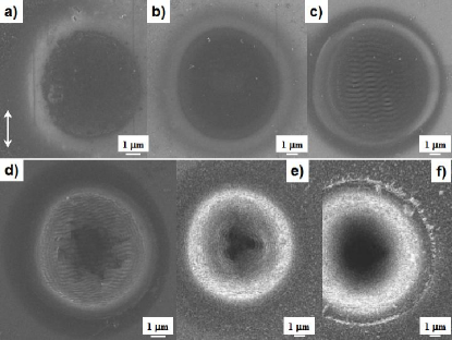
Surface ablation of the crystalline diamond occur for fs-laser intensities, exceeding the single-shot ablation threshold (4) 14.4 TW/cm2 (Fig.8), but for longer exposures the threshold intensity decreases down to (1000) 2.1 TW/cm2, following the well-known accumulation relationship (4), where (Fig.9). The spallative origin of the external crater is clearly seen as the sharp crater edge in Fig.8f, however, at higher exposures another ablation mechanism – apparently, phase explosion – comes into play for , forming the deep central dips and destroying the intermediate LIPSS (Figs.8d-f).
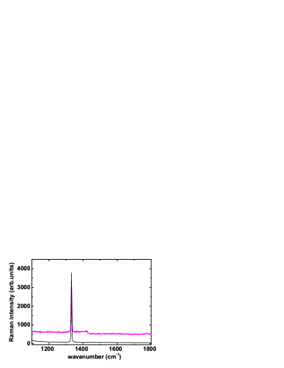
The observed cumulative decrease of the surface ablation threshold can be related, e.g., to the increasing coloration shown by SEM as darker ablated spots in Fig.8, as well as to stress, structural damage and ablative modification of the crater surface (Fig.8a-c). In particular, micro-Raman characterization of the craters, exhibiting only slightly displaced D-band with low-intensity background (Fig.10), is in agreement with some previous fs-laser nanostructuring studies on diamond surfaces Shinoda2009 ; Calvani2014 , showing rather clean nanostructured surfaces. The low-intensity ultrabroad (1100-11400 cm difference spectral band is known to yield from luminescence of nanoscale clusters Tan2013 ,rather than from the pump radiation, since both these spectra exhibit similar D-band intensities and the pump radiation was cut in the experiments in the same way. Moreover, the displaced ( 0.1 cm D-band shown by the corresponding bipolar band in the difference Raman spectrum (Fig.10), indicates the internal residual stresses kbar, according to the known calibration coefficient for this band 0.336 cm-1 / kbar Mitra1969 .
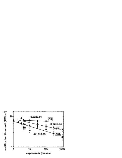
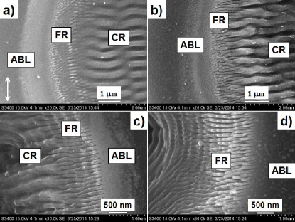
Fine and coarse surface ripples appear within the ablative craters, starting from , inside the surface regions limited by and (Fig.11), respectively. These thresholds exhibit two different trends with the increasing exposure – monotonous decrease for scaling as for intensities from to TW/cm2 (Fig.9) and almost no variation for (scaling as ) for intensities in the range from to TW/cm2 (Fig.9). The minor variation of potentially indicates that the CR are formed due to scattering mechanism, i.e. independent on the surface absorption, while surface absorption is more crucial for the formation of fine ripples.
Moreover, in comparison to fine ripples with threshold , coarse ripples, having considerably higher threshold , disappear in the central crater part for because of the pronounced ablation in this region (cf. Fig.8 and Fig.11). Fig. 11 shows that considerable CR erosion is present for 30 and 100.
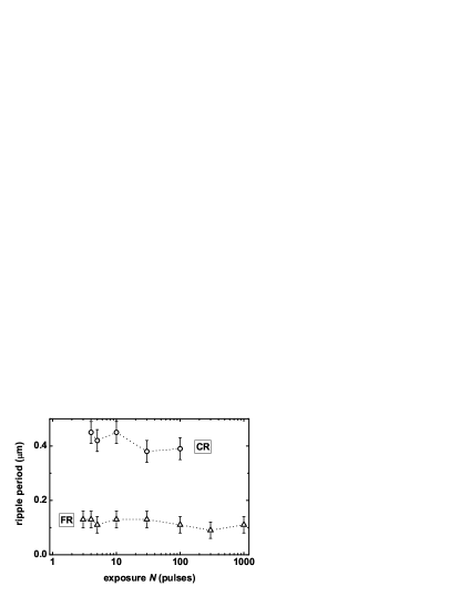
Most importantly, the small difference between the CR periods (0.45 , wavenumber m and the laser wavelength (0.515 m, wavenumber 1.9 m points out that long-wavelength micron-scale (m) perturbations of surface relief (permanent or cumulative ones – e.g., the spallative crater edge for 1) or optical characteristics (prompt or cumulative ones) Ionin2015 ; Ionin2013 are responsible for excitation of the underlying near-wavelength plasmon-polaritons. The corresponding FR and CR periods decrease versus – from till m and from till m (Fig.12), respectively, in agreement with cumulative trends known for FR and CR Huang2009_2 ; Bonse2010 ; Tsibidis2015 ; Ionin2015
III.2 Interpretation of LIPSS as imprints of transient SPP modes
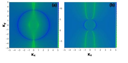
To make possible identification and interpretation of experimentally obtained SPP modes we plot the efficacy factor as a function of the wave vector in a narrow laser intensity range above the optical breakdown threshold in Fig.13 a-b. The transient bulk dielectric function was evaluated at the laser wavelength, i.e. . The surface roughness was modeled as a collection of spherically-shaped islands corresponding to standard values and for the shape and filling factors respectively. For normally incident light pulse, the numerical results are weakly dependent on the specific parameters describing surface morphology and therefore the transient dielectric constant is the most significant in determining the efficacy factor. Here we demonstrate that the main features in the inhomogeneous energy deposition in the surface as represented by the position of the peaks of the transient efficacy factor are in correspondence with the experimentally observed LIPSS periods.
In a very narrow laser intensity range, when the laser frequency nearly matches the surface plasma frequency (Fig. 13a), the efficacy factor has large contribution due to excitation of the surface plasmon resonance (SPR). In this early stage, the spatial extension of the electromagnetic field inside the bulk associated with SPP is determined by the SPR decay constant , which at short wavelengths defines a skin-depth leading to strong concentration of the electromagnetic field in the thin selvedge region. SPPs need finite time to build up to incorporate the details of the surface relief and interfere with the laser to modify the Fourier components of the surface roughness function via periodic laser ablation. In this regime the deposition of laser energy into the surface plasmon wavevector causes formation of fine ripples with spatial periods around 100 nm, as observed in the periphery of the ablative craters, cf. Fig.11. The transverse-magnetic characteristic of the SPP determines the orientation of the surface ripples. At a later time, the transiently increasing number of conduction electrons makes the dielectric constant large and negative at the laser wavelength, the intensity map of shrinks and concentrates on the outer part of the circle (cf. Fig 13b) which clearly can be associated with the formation of near-wavelength surface ripples oriented perpendicularly to the laser polarization. At the longer wavelengths with the skin depth nm is much smaller than the laser wavelength. Therefore, above the SPR excitation threshold, the transiently increasing carrier density results in a shift of the SPP wave number from the high spatial frequency region towards the light line (also causing expansion of the skin depth), and this red shift is highly sensitive on the carrier density (or laser intensity), cf. Fig.14a. The surface plasmon peak in the efficacy factor is also affected by the relaxation time parameter as shown in Fig. 14b. If is decreased to 10 fs, the surface plasmon cusp turns into a dip, which hinders the efficient energy absorption at the surface plasmon wavevector. This dependence suggests that the Drude carrier relaxation time parameter influences prompt feedback mechanisms involved in the formation of surface ripples. Indeed in the high-frequency limit with , the metalized surface behaves as a nearly ideal inductor, while in the low-frequency limit , the resistive Ohmic losses result in electron heating in the skin layer.
Because the efficacy factor theory does not fully account for interpulse feedback processes that are undoubtedly important in the detailed development of morphological features on the diamond surface our theoretical results are not directly applicable to the multipulse phase of LIPSS formation. However the experimental data shows that once surface ripples are formed, exposure by subsequent pulses has little effect on their spatial period and location, thus LIPSS formation should be possible already for a single-pulse irradiation, provided that SPP can be excited, e.g., by surface defects Jia2015 . Once LIPSS are formed, the spectrum of the surface roughness, contains peaks at the SPP wavenumber causing enhanced inhomogeneous energy deposition and further growth of LIPSS as is also evidenced from the SEM images in Fig.11a-b. Furthermore the subsequent pulses interact with periodically structured surface hence a grating-assisted laser-surface coupling becomes effective Huang2009_1 causing a decrease of the ripple wavelength. The experimental data shows only minor modification of LIPSS periods that is consistent with the hypothesis in Ref. Huang2009_1 that because of strong thermal effect at the crater center, the grating-assisted coupling is weak and the ripple wavelength is unaffected by higher exposure, i.e. depends weakly on the superimposed pulse number.

IV Conclusion
The influence of prompt and cumulative optical feedback contributions in multi-shot fs-laser induced dynamics of surface ripples was investigated theoretically and experimentally. The numerical simulations of periodic laser energy deposition on photo-excited diamond surface based on Sipe-Drude theory provided realistic and detailed insight into microscopic mechanisms. The model identifies the impact ionization as a relevant process causing optical breakdown of diamond in the trailing edge of the pulse resulting in plasmonically-active substrate with negative bulk dielectric constant triggering the SPP-laser interference mechanism for surface ripple formation. Fine ripples oriented perpendicularly to the laser polarization emerge for intensities in a narrow range above the optical breakdown threshold and the transient increase of the carrier density above this threshold results in the formation of near-wavelength surface ripples. The interpulse feedback mechanisms involved in LIPSS formation are not considered by the present theory and further work will be carried out in this direction. The obtained results lay the groundwork for utilizing diamond as a plasmonic material supporting subwavelength and intense SPPs that is very promising for advanced optical applications.
Acknowledgements
This work was partially supported by the Russian Foundation for Basic Research (projects nos. 17-52-53003, 17-02-00293 and 17-52-18023) and the grant of the RAS Presidium program, as well as by the Government of the Russian Federation (Grant 074-U01) through ITMO Visiting Professorship Program for S.I.K. This material is based upon work supported by the Air Force Office of Scientific Research, Air Force Material Command, USAF under Award No. FA9550-15-1-0197 (T.A.).
References
- (1) J. Isberg, J. Hammersberg, E. Johansson, T. Wikström, D. J. Twitchen, A. J. Whitehead, S. E. Coe, and G. A. Scarsbrook, Science 297, 1670 (2002).
- (2) I. Aharonovich and E. Neu, Advanced Optical Materials 2, 911 (2014).
- (3) B. J. M. Hausmann, B. Shields, Q. Quan, P. Maletinsky, M. McCutcheon, J. T. Choy, T. M.Babinec, A. Kubanek, A. Yacoby, M. D. Lukin, and M. Loncar, Nano Letters 12, 1578 (2012).
- (4) A. I. Kuznetsov , A. E. Miroshnichenko, M. L.Brongersma, Y. S.Kivshar, and B. Lukyanchuk, B., Science, 354, 2472 (2016).
- (5) A. M. Ozkan, A. P. Malshe, T. A. Railkar, W. D. Brownd, M. D. Shirk and P. A. Molian, Appl. Phys. Lett. 75, 3716 (1999).
- (6) M. H. Pham, D. V. Pham, T. H. Do, A.K. Ivanova, A.A. Ionin, S.I. Kudryashov, A.O. Levchenko, L. Nguyen, T.T.H. Nguyen, A.A. Rudenko, I.N. Saraeva, Communications in Physics 26 (2016).
- (7) A.K. Ivanova, A.A. Ionin, R.A. Khmelnitskii, S.I. Kudryashov, A.O. Levchenko, N.N. Mel’nik, A.A. Rudenko, I.N. Saraeva, S.P. Umanskaya, D.A.Zayarny, Laser Physics Letters (2016). (submitted)
- (8) A. Boltasseva and H. A. Atwater Science 331, 290 (2011).
- (9) S. Kumar Das, H. Messaoudi, A. Debroy, E. McGlynn and R. Grunwald, Optical Materials Express, 3 , 1705 (2013).
- (10) P.A. Danilov, A.A. Ionin, S.I. Kudryashov, S.V. Makarov, A.A. Rudenko, P.N. Saltuganov, L.V. Seleznev, V.I. Yurovskikh, D.A. Zayarny, T. Apostolova, J. Exp.Theor. Phys. 120, 946 (2015).
- (11) M. Z. Alam, I. De Leon, R. W. Boyd, Science 352, 795 (2016).
- (12) S. Jahani, Z. Jacob, Nature Nanotechnology, 11, 23 (2016).
- (13) P. R. West, S. Ishii, G. V. Naik, N. K. Emani, V. M. Shalaev, and A. Boltasseva, Laser Photonics Rev. 4, 795 (2010).
- (14) G. V. Naik, Pr V. M. Shalaev, A. Boltasseva, Adv. Mater. 25, 3264 (2013).
- (15) G. Miyaji and K. Miyazaki, Optics Express 16,16265 (2008).
- (16) M. Shinoda, R. R. Gattass and E. Mazur, J. Appl. Phys. 105, 053102 (2009).
- (17) Q. Wu, Y. Ma, R. Fang, Y. Liao, and Q. Yu, Appl. Phys. Lett. 82, 1703 (2003).
- (18) N. Yasumaru, K. Miyazaki, J. Kiuchi, Appl. Phys. A 76, 983 (2003).
- (19) J. Bonse, A. Rosenfeld, and J. Krüger. J. Appl. Phys., 106, 104910 (2009).
- (20) J. Gottmann, D. Wortmann, M. Hoš rstmann-Jungemann, Appl. Surf. Sci. 255, 5641 (2009).
- (21) T.T.J.-Y. Derrien, T.E. Itina, R. Torres, T. Sarnet, M. Sentis, J. Appl. Phys. 114, 083104 (2013).
- (22) K. Miyazaki, N. Maekawa, W. Kobayashi, M. Kaku, N. Yasumaru, & J. Kiuchi, Appl. Phys. A 80, 17 (2005).
- (23) P. Calvani, A. Bellucci, M. Girolami, S. Orlando, V. Valentini, A. Lettino, & D. M. Trucchi, Applied Physics A 117, 25 (2014).
- (24) J.E. Sipe, J.F. Young, J.S. Preston, H.M. van Driel, Phys. Rev. B 214, 1141 (1983).
- (25) S.A. Akhmanov, V.I. Emelyanov, N.I. Koroteev, V.N. Seminogov, Sov. Phys. Usp. 28, 1084 (1985).
- (26) M. Huang, F. Zhao, Y. Cheng, N. Xu, and Z. Xu, Phys. Rev. B, 79, 125436 (2009).
- (27) O. Varlamova, J. Reif, S. Varlamov and M. Bestehorn, Appl. Surf. Sci. 252, 4702 (2006).
- (28) G. Tsibidis, M. Barberoglou, P. Loukakos, E. Stratakis, and C. Fotakis. Phys. Rev. B 86, 115316 (2012).
- (29) M. Huang, F. Zhao, Y. Cheng, N. Xu, and Z. Xu, ACS Nano 3, 4062 (2009).
- (30) J. Bonse, J. Krüger,J. Appl. Phys. 108, 034903 (2010).
- (31) G. D. Tsibidis, E. Skoulas , E. Stratakis, Opt. Lett. 40, 5172 (2015).
- (32) A.A. Ionin, S.I. Kudryashov, S.V.Makarov, L.V. Seleznev, and D.V. Sinitsyn, Laser Physics Letters 12, 025902 (2015).
- (33) A.A. Ionin, S.I. Kudryashov, L.V. Seleznev, D.V. Sinitsyn, V.I. Emel’yanov, JETP Lett. 97,121, (2013).
- (34) A. Borowiec and H. K. Hagen, Appl. Phys. Lett. 82, 4462 (2003).
- (35) E.V. Golosov, A.A. Ionin, Yu.R. Kolobov, S.I. Kudryashov, A. E. Ligachev, S.V. Makarov, Yu.N. Novoselov, L.V. Seleznev, D.V. Sinitsyn, A.R. Sharipov, Phys. Rev. B 83, 115426 (2011).
- (36) C.S.R. Nathala, A. Ajami, A.A. Ionin, S.I. Kudryashov, S.V. Makarov, T. Ganz, A. Assion, W. Husinsky, Optics Express 23, 5915 (2015).
- (37) S.I. Kudryashov, S.V. Makarov, A.A. Ionin, C.S.R Nathala, A. Ajami, T. Ganz, A. Assion, W. Husinsky, Opt. Lett. 40 , 4967 (2015).
- (38) A.A. Ionin, S.I. Kudryashov, S.V. Makarov, L.V. Seleznev, D.V. Sinitsyn, E.V. Golosov, O.A. Golosova, Yu.R. Kolobov, A.E. Ligachev, Applied Physics A 107, 301 (2012).
- (39) E.V. Golosov, V.I. Emel’yanov, A.A. Ionin, Yu.R. Kolobov, S.I. Kudryashov, A.E. Ligachev, Yu.N. Novoselov, L.V. Seleznev, and D.V. Sinitsyn, JETP Letters 90, 107 (2009).
- (40) A. A. Ionin, S. I. Kudryashov, S. V. Makarov, A. A. Rudenko, P. N. Saltuganov, L. V. Seleznev, E. S. Sunchugasheva, Appl. Surf. Sci. 292, 678 (2014).
- (41) S. Bashir, M. S. Rafique, W. Husinsky , Nucl. Instr. Meth. in Phys. Res. B: Beam Interactions with Materials and Atoms, 349, 230 (2015).
- (42) J. Reif, O. Varlamova, S. Varlamov M. Bestehorn, Appl. Phys. A 104, 969 (2011).
- (43) O. Varlamova, M. Bounhalli, J. Reif, Appl. Surf. Sci., 278, 62 (2013).
- (44) H. M. van Driel, J. E. Sipe, and J. F. Young, Phys. Rev. Lett. 49, 1955 (1982).
- (45) J. Bonse, M. Munz and H. Sturm, J. Appl. Phys. 97, 013538 (2005).
- (46) T. Q. Jia, H. X. Chen, M. Huang, F. L. Zhao, J. R. Qiu, R. X. Li, Z. Z. Xu, X. K. He, J. Zhang, and H. Kuroda, Phys. Rev. B 72, 125429 (2005).
- (47) D. Dufft, A. Rosenfeld, S. K. Das, R. Grunwald, and J. Bonse, J. Appl. Phys. 105, 034908 (2009).
- (48) P. C. Becker, H. L. Fragnito, C. H. Brito Cruz, R. L. Fork, J. E. Cunningham, J. E. Henry, and C. V. Shank, Phys. Rev. Lett. 61, 1647 (1988).
- (49) Y. Shimotsuma, P. G. Kazansky, J. Qiu, and K. Hirao, Phys. Rev. Lett. 91, 247405 (2003).
- (50) B. H. Christensen and P. Balling, Phys. Rev. B 79, 155424 (2009).
- (51) D. H. Reitze, , H. Ahn and M. C. Downer, Phys. Rev. B 45, 2677 (1992).
- (52) K. Sokolowski-Tinten, D. von der Linde, Phys. Rev. B 61, 2643 (2000).
- (53) S. A. Sato, K. Yabana, Y. Shinohara, T. Otobe, and G. F. Bertsch Phys. Rev. B 89, 064304 (2014).
- (54) S. A. Sato, K. Yabana, Y. Shinohara, T. Otobe and G. F. Bertsch, Phys. Rev. B 92, 205413 (2015).
- (55) J. Z. P. Skolski, G. R. B. E. Römer, J. V. Obona, V. Ocelik, A. J. Huis in’t Veld, and J. Th. M. De Hosson, Phys. Rev. B 85, 075320 (2012).
- (56) S. Lagomarsino, S. Sciortino, B. Obreshkov, T. Apostolova, C. Corsi, M. Bellini, E. Berdermann, and C. J. Schmidt, Phys. Rev. B 93, 085128 (2016).
- (57) E.J. Yoffa, Phys. Rev. B 21, 2415 (1980).
- (58) W. S. Fann, R. Storz, H. W. K. Tom, and J. Bokor, Phys. Rev. B 46, 13592 (1992).
- (59) T. Apostolova an Y. Hahn, J. Appl. Phys. 88, 1024 (2000).
- (60) B. C. Stewart, M. D. Feit, S. Herman, A. M. Rubenchik, B. W. Shore, and M. D. Perry, Phys. Rev. B 53, 11449 (1995).
- (61) T. Watanabe, T. Teraji, T. Ito, Y. Kamakura, and K. Taniguchi, Appl. J. Phys. 95, 4866 (2004).
- (62) R.H.M. Groeneveld, R. Sprik, A. Lagendijk, Phys. Rev. B 51, 11433 (1995).
- (63) K. El-Sayed in ”Microscopic Theory of Semiconductors Quantum Kinetics, Confinement and Lasers”, Edited by: S. W. Koch, World Scientific, (1995)
- (64) P. . Danilov, D. . Zayarny, A.A. Ionin, S.I. Kudryashov, T. .H. Nguyen, . . Rudenko, I.N. Saraeva, . . Kuchmizhak, .B. Vitrik, Yu.N. Kulchin, JETP Lett. 103 , 549 (2016)
- (65) D. Tan, S. Zhou, B. Xu, J. Qiu, Carbon 62, 374 (2013)
- (66) S. S. Mitra, O. Brafman, W. B. Daniels, R. K. Crawford, Phys. Rev., 186, 942 (1969).
- (67) X. Jia, T. Q. Jia, N. N. Peng, D. H. Feng, S. A. Zhang, and Z. R. Sun, J. Appl. Phys. 115, 143102 (2014).