Measurement of gamma quantum interaction point in plastic scintillator with WLS strips
Abstract
We demonstrated the feasibility of measuring the axial coordinate of a gamma quantum interaction point in a plastic scintillator bar via the detection of scintillation photons escaping from the scintillator with an array of wavelength-shifting (WLS) strips. Using a test set-up comprising a BC-420 scintillator bar and an array of sixteen BC-482A WLS strips we achieved a spatial resolution of 5 mm () for annihilation photons from a 22Na isotope. The studied method can be used to improve the spatial resolution of a plastic-scintillator-based PET scanner which is being developed by the J-PET collaboration.
keywords:
positron emission tomography , wavelength shifter , plastic scintillator , silicon photomultipliersMSC:
[2010] 00-01, 99-001 Introduction
Positron emission tomography (PET) traditionally uses inorganic scintillation crystals for detection of the annihilation photons [1], and progress in the PET technology is closely connected with the developments in the field of scintillation crystal detectors. However, one can also try to improve some of the PET performance parameters such as the time resolution or the spatial resolution by replacing the inorganic crystals with different types of detectors like straw tubes [2, 3], resistive plate chambers (RPCs) [4], silicon pad detectors [5] or liquid xenon detectors [6, 7, 8].
The J-PET collaboration developed a whole-body PET scanner based on plastic scintillators which will allow to reach a superior time-of-flight (TOF) resolution and a high spatial acceptance at a moderate price. The scanner consists of plastic scintillator bars read out at both ends by a pair of photomultipliers and arranged axially around a cylindrical tomograph tunnel [9, 10, 11, 12, 13]. The axial coordinate of the annihilation photon interaction point in the scintillator bar is derived from the difference of the light propagation time measured with the pair of photomultipliers.
Even with a high precision of the time difference measurement of 140 ps (), obtained with a prototype of the J-PET scanner, the corresponding position resolution in the axial direction is only moderate and amounts to about 10 mm () [14]. This only improves to about 9 mm when applying multi-threshold readout and signal reconstruction based on the mathematically advanced compressing sensing theory [15, 16]. Therefore, in order to obtain higher resolution, we propose to register scintillation light escaping the scintillator bar through a side wall using an array of wavelength-shifting (WLS) strips [17].
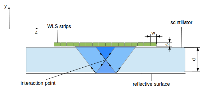
A schematic view of the setup is shown in Fig. 1. It shows the plastic scintillator bar and the array of WLS strips placed near the scintillator. Scintillation photons which can escape from the scintillator and reach the WLS array are emitted within two identical cones - forward and backward one - with the opening angle equal to twice the critical angle in the scintillator material. A specular surface is used for reflecting photons emitted within the backward cone towards the WLS array. In our test set-up, for an interaction point located on the scintillator axis, scintillation photons emitted in the forward and backward cone illuminate approximately 4 and 10 WLS strips, respectively. The coordinate of the interaction point along the scintillator bar (axial coordinate) can be determined on the basis of amplitudes measured in individual WLS strips e.g. by the center of gravity method.
The use of WLS strips for the readout of inorganic crystals in PET scanners was proposed in [18, 19]. However, the applicability of this method in the case of plastic scintillators is not obvious due to a substantially smaller light yield compared to inorganic crystals which is typically about 10000 photons per MeV energy deposition whereas for LYSO crystals it amounts to 32000 photons per MeV. Moreover, in plastic scintillators, gamma quanta with energy in the order of 1 MeV interact almost exclusively via the Compton effect and hence deposit only a part of their energy. Therefore, in order to demonstrate the applicability of WLS strips for determining the position of the gamma quantum interaction points in a plastic scintillator, we have built a test set-up for measuring the position of interaction of annihilation photons from a 22Na isotope. The set-up and the measurement results are described in the next two sections, respectively, and the paper is closed with conclusions.
2 Experimental set-up
A bar of BC-420 scintillator with a length of 300 mm, a width of 19 mm and a thickness of 5 mm is used for the registration of gamma quanta, and this is shown schematically in Fig. 2.
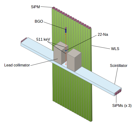
The type and dimensions of the scintillator bar are identical with the ones used in the J-PET prototype scanner [11]. The scintillator bar was read out on each end by three Hamamatsu S12572-050P silicon photomultipliers (SiPMs). Photons escaping from the bar through a 5 mm wide side wall were registered with an array of 16 WLS strips placed parallel to the wall with a 1.5 mm air gap left in between the WLS strips and the scintillator. The remaining three side walls of the scintillator were covered with reflective aluminium foil.
The WLS strips were 100 mm long, their width was 5 mm and the thickness was 3 mm. Neighbouring strips were separated by 0.1 mm gap and thus the active area covered by the strips along the scintillator bar was 81.5 mm (= mm mm).
Each WLS strip was read out at one end with a Hamamatsu S12572-050P SiPM having an active area of mm2 and thus covering 60% of the end face of the strip ( mm2). The opposite end of the strip was covered with aluminium foil that reflected re-emitted light towards the SiPM.
The WLS strips were made of BC-482A with three times enhanced dye concentration. For increasing the light absorption, an aluminium foil was placed behind the WLS array in order to reflect back the unabsorbed photons. The wavelength of maximum emission of the BC-420 scintillator equals 391 nm and thus the emission spectrum only partly overlaps with the range of strong absorption of BC-482A, which is 390-460 nm [20]. Based on measurements of the light transmission coefficient in ELJEN EJ-280 WLS [21], which is equivalent to BC-482A, we estimate that about 75% of the scintillation photons emitted orthogonally to the WLS array are absorbed in the array in our test set-up.
The wavelength of maximum emission of the BC-482A WLS equals 494 nm and fits well in the region of the highest photon detection efficiency of 400-500 nm of the applied SiPMs [22].
Test measurements were performed with annihilation photons from a 22Na source. For tagging of the photons we used a small scintillation detector containing a BGO crystal of mm2 cross section and a length of 10 mm, read out by a SiPM. The 1275 keV gamma quanta from the 22Na source were suppressed by a lead collimator with a 4 mm slit.
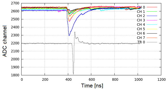
Signals of the SiPMs coupled to the WLS strips were amplified with Advatech-UK AMP-0604 amplifiers [23] and were sampled with CAEN Digitizer DT5742 [24] with a frequency of 1 GHz and a resolution of 12 bits. Readout of the digitizer was triggered by a coincidence of pulses from the plastic scintillator and the BGO detector, ensuring selection of annihilation quanta from the 22Na source. Typical pulses registered with the digitizer are shown in Fig. 3.
3 Results
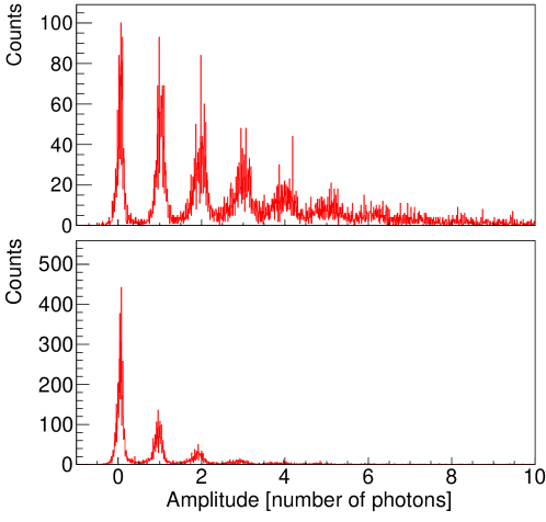
In the offline analysis, the recorded samples of the WLS and scintillator pulses were used to determine their amplitudes and arrival times. An example of amplitude spectra for two WLS strips - one located in front of the interaction point and the other lying 30 mm aside - is shown in Fig. 4. The mean number of photons registered in these strips is 3.8 and 0.8, respectively.
A distribution of time differences between the scintillator pulse and the WLS pulses is shown in Fig. 5. A fit to the falling edge of the distribution with a function exp gives a decay time of 7 ns which is shorter than the 12 ns decay time of the BC-482A plastic [20]. This difference can be explained by the fact that for a few re-emitted photons registered in a WLS strip, only the first one was taken into account in the time measurement based on leading edge discrimination.
In order to reduce accidental coincidences caused by the dark count rate of the SiPMs (1 MHz) a 50 ns time window was set on time differences between the scintillator pulse and the WLS pulses.

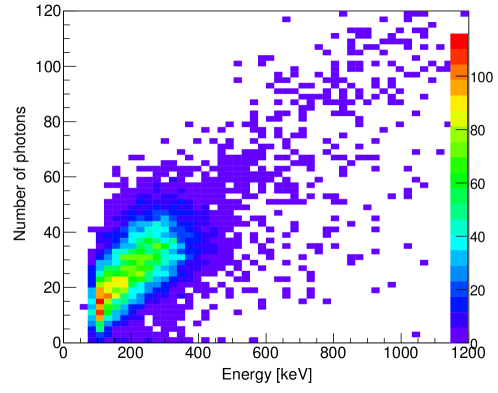
The annihilation photons are registered in plastic scintillator detectors via Compton scattering and the resulting spectrum of amplitudes of detector pulses has a continuous form. An energy calibration of the scintillator pulse amplitude, based on the position of the Compton edge for the annihilation photons in the spectrum, was performed. The number of scintillation photons registered in the WLS strips increases with the energy deposited in the plastic scintillator as shown in Fig. 6. The upper limit for the energy loss of the annihilation photons due to Compton scattering equals 341 keV and the corresponding number of photons registered in the WLS strips is about 38. This number has to be corrected for the cross talk in the applied Hamamatsu SiPMs, which equals about 25% for the applied overvoltage of 2.5 V [22]. Thus the true number of registered photons is about 30.
In order to compare an experimentally determined number of photons at the Compton edge with the expectations based on the properties of the detector set-up we have performed calculations taking into account the following efficiencies:
-
1.
0.22 - fraction of full solid angle for photons escaping the scintillator and reaching the WLS array,
-
2.
- fraction of photons passing the interfaces scintillator-air and air-WLS,
-
3.
0.75 - fraction of photons absorbed in WLS,
-
4.
0.86 - fluorescence efficiency of WLS,
-
5.
0.5 - fraction of confined photons propagating towards one end of a WLS strip,
-
6.
0.60 - coverage of WLS face with SiPM,
-
7.
0.62 - SiPM fill factor,
-
8.
0.35 - photon detection efficiency at 500 nm.
The percentage of registered photons obtained as a product of the above efficiencies equals 0.85%. The number of scintillation photons produced by electrons in the BC-420 scintillator is equal to about 10000 per 1 MeV energy deposit [25], which equates to 3400 scintillation photons for the 0.34 MeV electrons originating from the backward Compton scattering. The expected number of photons registered in the WLS strips equals 29 which is close to the experimental number of 30 photons.
For each registered event, the distribution of amplitudes of WLS pulses presented as a function of the WLS coordinates was fitted with a Gaussian function. The center of the function was taken as the reconstructed position of the gamma quantum interaction point. An example of such a fit is shown in Fig. 7.
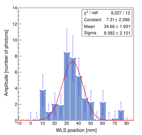
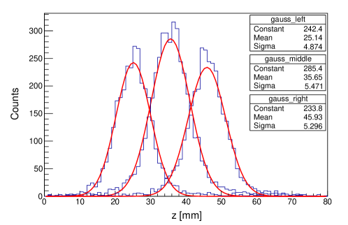
Figure 8 shows distributions of reconstructed positions for three locations of the 22Na source differing by 10 mm. A spatial resolution obtained by fitting the Gaussian function to these distributions is about 5 mm (). The centers of the fitted functions reproduce the real positions of the 22Na source within a positioning accuracy of the source of mm.
For comparison, we also performed a position reconstruction using a method based on taking an average coordinate of the WLS strips weighted with the registered amplitudes of the WLS pulses. The average was taken over seven neighbouring strips: a strip with the highest amplitude and two triplets of strips located on both sides of it. The position resolution obtained is of about 6 mm () and thus very similar to the one based on the Gaussian fit.
4 Conclusions
We have demonstrated that the interaction point of an annihilation gamma-quantum in a plastic scintillator bar can be localized by means of an array of WLS strips measuring scintillation photons escaping from the scintillator through a side wall. With our test set-up we reached a position resolution of 5 mm () for the coordinate along the scintillator bar. The achieved precision may be further improved e.g. by increasing the coverage of WLS face with SiPM (which was only 60%). Results presented in this article constitute a basis for construction of detection modules of the J-PET scanner. Each module will consist of a layer of thirteen plastic scintillator bars with dimensions of mm3 and a layer of WLS strips. The scintillators will be arranged parallel along the mm2 sides and the layer of WLS strips will view the mm2 side of the scintillators. The modules will be used to built a full scale J-PET detector which will enable experimentation in the field of nuclear medical imaging and tests of the discrete symmetries in the decays of positronium atoms [26, 27, 28].
5 Acknowledgements
We acknowledge the technical support of A. Mucha and A. Misiak, and financial support by the Polish Ministry of Science and Higher Education (Grant No. 2593/7.PR/2012/2).
References
- [1] P. J. Slomka, et al., Semin. Nucl. Med 46 (2016) 5–19.
- [2] N. N. Shehad, et al., IEEE 2005 Nuclear Science Symposium Conference Record 5 (2005) 2895–2898.
- [3] L. Sun, et al., IEEE 2007 Nuclear Science Symposium Conference Record 5 (2007) 3337–3344.
- [4] A. Blanco, et al., IEEE Trans. Nucl. Sci. 53 (2006) 2489.
- [5] S.-J. Park, et al., Nucl. Instrum. Methods A 570 (2007) 543–555.
- [6] T. Doke, et al., Nucl. Instrum. Methods A 569 (2006) 863–871.
- [7] P. Amaudruz, et al., Nucl. Instrum. Methods A 607 (2009) 668–767.
- [8] A. Miceli, et al., Phys. Med. Biol. 57 (2012) 1685–1700.
- [9] P. Moskal, et al., Bio-Algorithms and Med-Systems 7 (2011) 73.
- [10] P. Moskal, et al., Nuclear Medicine Review 15 (2012) C81–C84.
- [11] P. Moskal, et al., Nucl. Instrum. Methods A 764 (2014) 317.
- [12] P. Moskal, et al., Nucl. Instrum. Methods A 775 (2015) 54.
- [13] P. Moskal, et al., Phys. Med. Biol. 61 (2016) 2025–2047.
- [14] N. G. Sharma, et al., NUKLEONIKA 60 (2015) 765–769.
- [15] L. Raczynski, et al., Nucl. Instrum. Methods A 764 (2014) 186.
- [16] L. Raczynski, et al., Nucl. Instrum. Methods A 786 (2015) 105.
- [17] J. Smyrski, et al., Bio-Algorithms and Med-Systems 10 (2014) 59–63.
- [18] N. Belcari, et al., Nucl. Instrum. Methods A 461 (2001) 413–415.
- [19] A. Braem, et al., Nucl. Instrum. Methods A 580 (2007) 1513–1521.
- [20] Saint-Gobain general technical data of BC-482A.
- [21] A. Braem, et al., Nucl. Instrum. Methods A 586 (2008) 300–308.
- [22] Hamamatsu technical data sheet of S12572-050P, 2015.
- [23] Advatech–UK, specifications of AMP-0604 preamplifier available at http://www.advatech-uk.co.uk/index.html.
- [24] CAEN, DT5742 User Manual, http://www.caen.it/csite/HomePage.jsp.
- [25] S. A. Pozzi, J. A. Mullens, J. T. Mihalczo, Nucl. Instrum. Methods A 524 (2004) 92–101.
- [26] P. Moskal, et al., Acta Phys. Polon. B 47 (2016) 509.
- [27] D. Kamińska, et al., Eur. Phys. J. C 76 (2016) 445.
- [28] A. Gajos, et al., Nucl. Instrum. Methods A 819 (2016) 59.