High repetition rate ultrashort laser cuts a path through fog
Abstract
We experimentally demonstrate that the transmission of a 1030 nm, 1.3 ps laser beam of 100 mJ energy through fog increases when its repetition rate increases to the kHz range. Due to the efficient energy deposition by the laser filaments in the air, a shockwave ejects the fog droplets from a substantial volume of the beam, at a moderate energy cost. This process opens prospects for applications requiring the transmission of laser beams through fogs and clouds.
I Introduction
Lasers offer many actual or prospective applications at the atmospheric scale , including Kasparian and Wolf (2008), the remote delivery of high-intensity for surface ablation Garcia et al. (2000); Stelmaszczyk et al. (2004); Fujii et al. (2006); Tzortzakis et al. (2006), free-space communications Kiasaleh (2006); Belmonte et al. (1997); Polynkin et al. (2007), remote sensing Kasparian et al. (2003); Galvez et al. (2002); Gravel et al. (2004); Hemmer et al. (2011); Svanberg (2008), or weather modulation Kasparian et al. (2008); Henin et al. (2011); Ju et al. (2014). In that purpose, efficient transmission of the beam through the atmosphere is essential, and cloud and fogs constitute obvious obstacles.
When the incident peak power of a laser pulse exceeds a critical power ( GW in air at 1030 nm), focusing and defocusing non-linearities including the laser-generated plasma and the saturation of the medium polarisability under strong-field illumination Béjot et al. (2010); Volkova et al. (2011); Richter et al. (2013) result in a self-guided propagation regime: Filamentation Braun et al. (1995); Chin et al. (2005); Couairon and Mysyrowicz (2007); Bergé et al. (2007).
Laser filaments have a diameter of and are surrounded by a "photon bath" carrying most of the beam energy. This energy is able to re-create them after they have been blocked by an obstacle like a water drop Courvoisier et al. (2003); Kolesik and Moloney (2004); Skupin et al. (2004). However, since the photon bath undergoes elastic losses, the aerosols ultimately limit the filamentation length. Indeed, a filament cannot propagate without being fed by its photon bath Liu et al. (2005).
Laser filaments leave behind them a cylindric region where the air density is depleted Vidal et al. (2000) (a “density hole") with a lifetime of hundreds of microseconds Lahav et al. (2014); Jhajj et al. (2014); Cheng et al. (2013). In this work, we show that the associated shockwave "cleans" the atmosphere not only in the filament, but also a significant fraction of the photon bath.
This approach substantially differs from attempts to clear clouds and fogs in the 70’s and ‘80s with high-energy CO2 lasers, in which prohibitively high intensities and energies are needed to evaporate and shatter water drops (typically 10 kW/cm2 continuous wave lasers Zuev et al. (1984) and 1–1000 MW/cm2 pulsed lasers Kwok et al. (1988); Pustovalov and Khorunzhii (1992), respectively). Conversely, the energy of the shockwave can expell particles out of the beam, at a much lower energy cost.
By investigating the propagation of ultrashort (ps) laser pulses in the near-infrared through a dense fog, we show that the transmission increases with the repetition rate, i.e., with the average beam power. This increased transmission is due to the above-mentioned shockwave, expelling the particles from the central region of the beam, well beyond the volume of the filament itself. This thermo-mechanical effect is efficient beyond the filament volume and offers a prospect to improve laser beam transmission through fog and clouds.
II Experimental setup
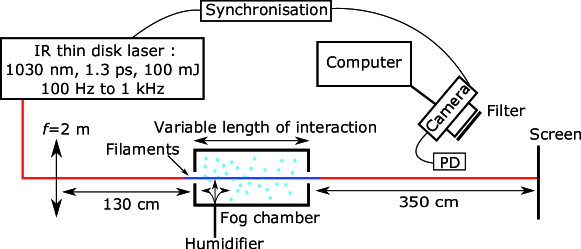
As sketched in Figure 1, the experiment consisted in
propagating the beam of an ultrashort laser beam through a chamber filled with fog.
The laser system was an Yb:YAG thin disk laser (Dira, TRUMPF Scientific Lasers GmbH + Co. KG Klingebiel et al. (2015)), delivering 1.3 ps pulses with 100 mJ energy at a wavelength of 1030 nm. The beam was slightly focused ( = 2 m). The repetition rate was varied between 100 and 1000 Hz, corresponding to average powers of 10 to 100 W. The peak power of 75 GW corresponds to 15 critical powers. As a result, typically 3–4 filaments of 50 cm length were observed on the screen. Considering that each of them carries an energy = 5 mJ, 3 filaments carry 15 mJ, i.e, 15% of the total beam energy of 100 mJ.
3.5 m after the fog chamber, the beam was imaged on a screen and its profile recorded by a PixelInk PL-B761U CCD camera with 480 x 752 pixels. Approximately 1900 single-shot images were recorded for each experimental condition through a Schott BG7 filter, that blocked the continuum in the 700–900 nm spectral region, but only attenuates the fundamental wavelength. The energy transmitted through the fog was calculated as the profile-integrated fluence on the screen, and normalized by a reference measurement without fog.
The fog was produced by a large volume droplet generator and introduced into a 40 cm long chamber. Leaks through the openings implied an interaction length of 50 cm between the laser beam and the fog. Alternatively, the fog at the exhaust of the generator was directly blown onto the laser beam, offering propagation through 6 cm of fog. In either case, the fog interacted with the most intense longitudinal section of the filament, i.e., where the plasma noise was strongest.
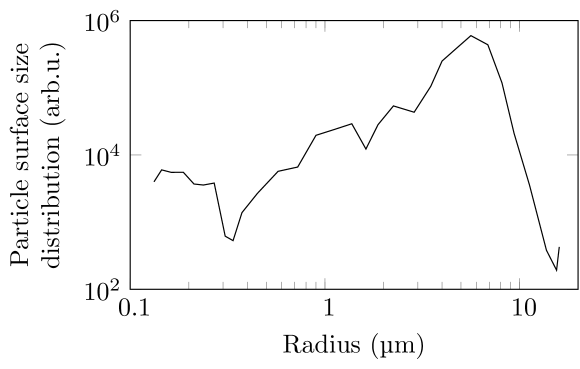
The fog droplet size distribution (Figure 2) was measured by using an optical aerosol sizer (Grimm, model 1.109). We checked that the size distribution was homogeneous across the fog chamber, and cross-checked the typical size with direct imaging of the particles impacted on a glass surface. The mode of this size distribution is , compatible with typical fog conditions in the atmosphere. In order to reach optical densities encountered in fogs on the meter-scale of the laboratory, the concentration of droplets was increased by a factor of typically 100 as compared with actual fogs.
III Results and discussion
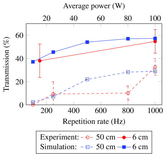
Figure 3 displays the beam transmission as a function of the repetition rate of the laser. Higher repetition rates, associated with average beam powers up to 100 W, clearly increase the transmission of the beam through the fog, from 0.1% at 100 Hz, to 32% at 1 kHz. As mentioned above, the three filaments carry only 15% of the beam energy. The observed increase in the transmission therefore implies that at high repetition rates the laser transmission also increases in the lower-intensity photon bath.
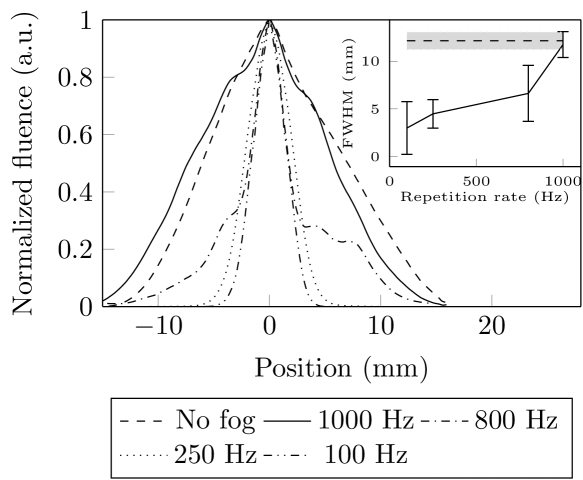
Indeed, the higher transmission is associated with an wider transmitted beam (Figure 4). While at 100 Hz repetition rate only the central part of the profile on the screen is (partially) transmitted, at 1 kHz this part covers almost the whole beam. In other words, increasing the repetition rate (hence, the average power and the deposited heat) increases both the transmission in the beam center and the width of the region over which this transmission is increased.
The vaporization or the shattering of the water droplets present in the filament volume would at most result in the full transmission of the filaments, that as discussed above carry only 15% of the beam energy. It cannot further increase the beam transmission, nor extend the size of the transmitted region of the beam. To explain these observations, droplets have to be ejected also from the photon bath. This is made possible by the shockwave in the air associated to local heating Jhajj et al. (2014), due to the cumulative energy deposition Lahav et al. (2014) by the filaments in the air (typically 2% at 1 kHz Houard et al. (2016)).
The heat deposited by filaments in conditions comparable to ours typically generates a depleted channel with a local pressure reduced to atm Vidal et al. (2000); Jhajj et al. (2014), implying that the corresponding air parcel doubles volume. As a consequence, we assumed that the shockwave sweeps a volume at least twice as large as that of the filaments, i.e., a cylinder of radius for a filament radius of . Based on the temporal evolution of the air density calculated by Vidal et al. (2000), we considered an air radial expansion speed m/s for and a collapse speed mm/s for . Outside of these two time intervals, we consider that the air stays still. We solved the equation of motion of the droplets under aerodynamic drag Belkhelfa (2008), assuming that they keep their spherical shape:
| (1) |
where is air density and is the drag coefficient for a sphere. We find that the shockwave has a net effect of ejecting the droplets of radius at a speed of mm/s out of both the filament and its surrounding photon bath.
The balance between the particle ejection by the shockwave and the advection by the transverse wind can be characterized by calculating the net flux of particles through the outer surface of the region swept by the shockwave, modeled as a cylinder of length and radius :
| (2) |
where is the number of particles in the considered volume, is the time, and is the drop concentration far from the filament (as supplied by the droplet generator). The advection speed of the incoming droplets is estimated to be 12 mm/s based on the droplet generator flow and chamber geometry.
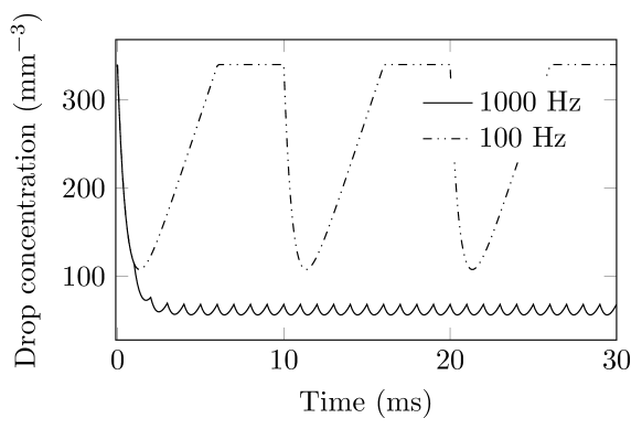
Figure 5 displays the droplet concentration evolution within the cylinder swept by the shockwave, based on integrating Eq. (2). At 100 Hz, the advection is sufficiently fast to replenish the droplet concentration between two pulses. In contrast, at 1 kHz, the advection is too slow, so that the droplet concentration decreases. After 3–5 pulses, it reaches a steady regime in which advection and droplet expulsion by the shockwave balance each other. The droplet concentration has then dropped by a factor of almost 6 from 344 to 60 mm-3. The concentration estimated by this approach is independent from the diameter of the considered cylinder, because the drag force of the air is insufficient to slow them down significantly over a few milliseconds: Their speed can be considered constant at the investigated time scales.
To precisely estimate the effect of droplet ejection by the shockwave on the transmission of the beam, we modeled in two dimensions the interaction of droplets carried by an advection flow, under the influence of the laser-generated shockwave. More specifically, we performed Monte-Carlo simulations of the trajectory of droplets of radius , with an initial advection speed =12 mm/s transverse to the laser beam. At each laser pulse, droplets located within the area swept by the shockwave associated with each of the three filament are ejected radially at a speed of 60 mm/s. The resulting droplet concentration map is then used to compute Mie scattering for the effective particle radius and hence determine the local transmission, that is then integrated over the beam fluence profile to yield the beam transmission value. Propagation lengths of both 50 cm and 6 cm, representative of the experiments, have been considered.
In order to match the experimental parameters, the beam is modeled as a Gaussian beam with a FWHM diameter of 5 mm, with 3 filaments evenly positioned on a circle with 0.7 mm radius around the beam center. The orientation of the triangle formed by the 3 filaments evolves randomly from shot to shot. We checked that the results were insensitive to the details of this motion.
A droplet-depleted region appears downstream of the filamenting region. The corresponding rise of the transmission of the photon bath contributes to one half of the the observed transmission increase at high repetition rates. As shown in Figure 3, this model reproduces well the experimental results for an initial droplet concentration of 344 mm-3, demonstrating the key role of the shockwave in clearing the fog and increasing the laser beam transmission. Note that the discrepancy with the experimental point at 800 Hz is due to a lower stability of the laser beam at this repetition rate, that limits the cumulative thermal effect. Although the size mode of actual fog is slightly lower (), one can expect that our results can be extended at least to atmospheric ranges in a dense fog.
IV Conclusion
As a conclusion, we investigated the transmission of a high-average power, high-repetition rate ultrashort laser beam through a dense fog. Due to the energy deposition in the air, a shockwave expels the fog droplets not only within the filament volume, but also from the photon bath. As a consequence, a drastically improved beam transmission is observed. This effect increases for higher repetition rates where the balance between the said expulsion and the advection of new background droplets favors more the former.
This work therefore opens prospects to improved laser beam transmission through fog, opening promising perspectives to point-to-point laser communication, remote sensing, or lightning control through clouds.
Acknowledgments We acknowledge financial support from the ERC advanced grant « Filatmo ». The authors thank M. Moret for technical support.
References
- Kasparian and Wolf (2008) J. Kasparian and J.-P. Wolf, Optics Express 16, 466 (2008).
- Garcia et al. (2000) C. C. Garcia, M. Corral, J. M. Vadillo, and J. J. Laserna, Applied Spectroscopy 54, 1027 (2000).
- Stelmaszczyk et al. (2004) K. Stelmaszczyk, P. Rohwetter, G. Méjean, J. Yu, E. Salmon, J. Kasparian, R. Ackermann, J.-P. Wolf, and L. Wöste, Applied Physics Letters 85, 3977 (2004).
- Fujii et al. (2006) T. Fujii, N. Goto, M. Miki, T. Nayuki, and K. Nemoto, Optics Letters 31, 3456 (2006).
- Tzortzakis et al. (2006) S. Tzortzakis, D. Anglos, and D. Gray, Optics Letters 31, 1139 (2006).
- Kiasaleh (2006) K. Kiasaleh, JOSA A 23, 557 (2006).
- Belmonte et al. (1997) A. Belmonte, A. Comerón, J. A. Rubio, J. Bará, and E. Fernández, Applied Optics 36, 8632 (1997).
- Polynkin et al. (2007) P. Polynkin, A. Peleg, L. Klein, T. Rhoadarmer, and J. Moloney, Optics Letters 32, 885 (2007).
- Kasparian et al. (2003) J. Kasparian, M. Rodriguez, G. Méjean, J. Yu, E. Salmon, H. Wille, R. Bourayou, S. Frey, Y.-B. André, A. Mysyrowicz, R. Sauerbrey, J.-P. Wolf, and L. Wöste, Science 301, 61 (2003).
- Galvez et al. (2002) M. C. Galvez, M. Fujita, N. Inoue, R. Moriki, Y. Izawa, and C. Yamanaka, Japanese journal of applied physics 41, L284 (2002).
- Gravel et al. (2004) J.-F. Gravel, Q. Luo, D. Boudreau, X. P. Tang, and S. L. Chin, Analytical Chemistry 76, 4799 (2004).
- Hemmer et al. (2011) P. R. Hemmer, R. B. Miles, P. Polynkin, T. Siebert, A. V. Sokolov, P. Sprangle, and M. O. Scully, Proceedings of the National Academy of Sciences 108, 3130 (2011).
- Svanberg (2008) S. Svanberg, Applied Physics B: Lasers and Optics 92, 351 (2008), 10.1007/s00340-008-3092-5.
- Kasparian et al. (2008) J. Kasparian, R. Ackermann, Y.-B. André, G. Méchain, G. Méjean, B. Prade, P. Rohwetter, E. Salmon, K. Stelmaszczyk, J. Yu, A. Mysyrowicz, R. Sauerbrey, L. Wöste, and J.-P. Wolf, Optics Express 16, 5757 (2008).
- Henin et al. (2011) S. Henin, Y. Petit, P. Rohwetter, K. Stelmaszczyk, Z. Hao, W. Nakaema, A. Vogel, T. Pohl, F. Schneider, J. Kasparian, K. Weber, L. Wöste, and J. Wolf, Nature Communications 2, 456 (2011).
- Ju et al. (2014) J. Ju, T. Leisner, H. Sun, A. Sridharan, T.-J. Wang, J. Wang, C. Wang, J. Liu, R. Li, Z. Xu, and S. L. Chin, Applied Physics B 117, 1001 (2014).
- Béjot et al. (2010) P. Béjot, J. Kasparian, S. Henin, V. Loriot, T. Vieillard, E. Hertz, O. Faucher, B. Lavorel, and J.-P. Wolf, Physical Review Letters 104, 103903 (2010).
- Volkova et al. (2011) E. A. Volkova, A. M. Popov, and O. V. Tikhonova, JETP Letters 94, 519 (2011).
- Richter et al. (2013) M. Richter, S. Patchkovskii, F. Morales, O. Smirnova, and M. Ivanov, New Journal of Physics 15, 083012 (2013).
- Braun et al. (1995) A. Braun, G. Korn, X. Liu, D. Du, J. Squier, and G. Mourou, Optics Letters 20, 73 (1995).
- Chin et al. (2005) S. L. Chin, S. A. Hosseini, W. Liu, Q. Luo, F. Théberge, N. Aközbek, A. Becker, V. P. Kandidov, O. G. Kosareva, and H. Schröder, Canadian Journal of Physics 83, 863 (2005).
- Couairon and Mysyrowicz (2007) A. Couairon and A. Mysyrowicz, Physics Reports 441, 47 (2007).
- Bergé et al. (2007) L. Bergé, S. Skupin, R. Nuter, J. Kasparian, and J.-P. Wolf, Reports on progress in physics 70, 1633 (2007), arXiv: physics/0612063.
- Courvoisier et al. (2003) F. Courvoisier, V. Boutou, J. Kasparian, E. Salmon, G. Méjean, J. Yu, and J.-P. Wolf, Applied Physics Letters 83, 213 (2003).
- Kolesik and Moloney (2004) M. Kolesik and J. V. Moloney, Optics Letters 29, 590 (2004).
- Skupin et al. (2004) S. Skupin, L. Bergé, U. Peschel, and F. Luderer, Physical Review Letters 93, 023901 (2004).
- Liu et al. (2005) W. Liu, F. Théberge, E. Arévalo, J.-F. Gravel, A. Becker, and S. L. Chin, Optics Letters 30, 2602 (2005).
- Vidal et al. (2000) F. Vidal, D. Comtois, C.-Y. Chien, A. Desparois, B. L. Fontaine, T. W. Johnston, J. C. Kieffer, H. P. Mercure, H. Pepin, and F. A. Rizk, IEEE Transactions on Plasma Science 28, 418 (2000).
- Lahav et al. (2014) O. Lahav, L. Levi, I. Orr, R. A. Nemirovsky, J. Nemirovsky, I. Kaminer, M. Segev, and O. Cohen, Phys. Rev. A 90, 021801 (2014).
- Jhajj et al. (2014) N. Jhajj, E. W. Rosenthal, R. Birnbaum, J. K. Wahlstrand, and H. M. Milchberg, Phys. Rev. X 4, 011027 (2014).
- Cheng et al. (2013) Y.-H. Cheng, J. K. Wahlstrand, N. Jhajj, and H. M. Milchberg, Optics Express 21, 4740 (2013).
- Zuev et al. (1984) V. E. Zuev, A. A. Zemlyanov, Y. D. Kopytin, and A. V. Kuzikovskii, High-power laser radiation in atmospheric aerosols (D. Reidel Publishing Company, Dordrecht / Boston / Lancaster, 1984).
- Kwok et al. (1988) H. S. Kwok, T. M. Rossi, W. S. Lau, and D. T. Shaw, Optics Letters 13, 192 (1988).
- Pustovalov and Khorunzhii (1992) V. Pustovalov and I. Khorunzhii, Int J. Heat Mass Transf. 35, 583 (1992).
- Klingebiel et al. (2015) S. Klingebiel, M. Schultze, C. Teisset, R. Bessing, M. Haefner, S. Prinz, M. Gorjan, D. Sutter, K. Michel, H. Barros, Z. Major, F. Krausz, and T. Metzger, in CLEO: 2015, OSA Technical Digest (online) (Optical Society of America, 2015, 2015) p. Paper STu4O.2.
- Houard et al. (2016) A. Houard, V. Jukna, G. Point, Y.-B. André, S. Klingebiel, M. Schultze, K. Michel, T. Metzger, and A. Mysyrowicz, Opt. Express 24, 7437 (2016).
- Belkhelfa (2008) Y. Belkhelfa, Etude du comportement dynamique et du transfert de matière et de chaleur entre des particules sphériques et un écoulement laminaire ou turbulent, Ph.D. thesis, L’institut national des sciences appliquées de Rouen (2008).