Resonator with ultra-high length stability as a probe for Equivalence-Principle-violating physics
Abstract
In order to investigate the long-term dimensional stability of matter, we have operated an optical resonator fabricated from crystalline silicon at 1.5 K continuously for over one year and repeatedly compared its resonance frequency with the frequency of a GPS-monitored hydrogen maser. After allowing for an initial settling time, over a 163-day interval we found a mean fractional drift magnitude /s. The resonator frequency is determined by the physical length and the speed of light, and we measure it with respect to the atomic unit of time. Thus, the bound rules out, to first order, a hypothetical differential effect of the universe’s expansion on rulers and atomic clocks. We also constrain a hypothetical violation of the principle of Local Position Invariance for resonator-based clocks and derive bounds for the strength of space-time fluctuations.
In this paper we address experimentally the question about the intrinsic time-stability of the length of a macroscopic solid body. This question is related to the question about time-variation of the fundamental constants and effects of the expansion of the universe on local experiments. It may be hypothesized that, in violation of the Einstein Equivalence Principle (EP), the expansion affects the length of a block of solid matter and atomic energies to a different degree. The length, defined by a multiple of an interatomic spacing, can be measured by clocking the propagation time of an electromagnetic wave across it. This procedure effectively implements the Einstein light clock, or, in modern parlance, an electromagnetic resonator. The hypothetical differential effect would show up as a time-drift of the ratio of the frequency of an electromagnetic resonator and of an atomic (or molecular) transition (). A resonator and an atom are dissimilar in the sense that the former’s resonance frequency intrinsically involves the propagation of an electromagnetic wave, while the latter does not. Specifically, the time-drift would violate the principle of Local Position Invariance (LPI) of EP. The natural scale of an effect due to cosmological expansion, here the fractional drift rate , is the Hubble constant /s. Extensive work in the last decade has ruled out that an effect of this order exists between different atomic and molecular frequency standards Uzan2011 .
The suitable regime in which to investigate the dimensional stability of matter is at cryogenic temperature, when the thermal expansion coefficient and the thermal energy content of matter are minimized. Ideally, during the cooling down and then permanence at cryogenic temperature, a stable energy minimum of the solid is reached. The expected high dimensional stability and the magnitude of lead to a challenging measurement problem: how to resolve tiny length changes, and how to suppress the influence of extrinsic disturbances. The problem can be addressed by casting the solid matter into an electromagnetic resonator of appropriate shape, by supporting it appropriately, and by measuring its resonance frequency using atomic time-keeping and frequency metrology instruments, which indeed permit ultra-high measurement precision and accuracy.
Cryogenically operated resonators Turneaure1983 have been developed for microwave and optical frequencies. These represent a viable approach for realizing oscillators having ultra-high stability both on short and on long time scale (months). Therefore, they have found applications for tests of EP Turneaure1983 ; Braxmaier2002 ; Muller2003a ; Antonini2005 ; Schiller2004 ; Tobar2010 and as local oscillators in connection with microwave and optical atomic clocks Millo2009a ; Kessler2012a .
Recent cryogenic microwave sapphire resonators exhibit nonzero fractional drifts of s Tobar2010 and s Hartnett2012 and the lowest value reported was s during a 9-day long interval Hartnett2006 . For a sapphire cryogenic optical resonator Seel1997 a mean drift smaller than s was measured Storz1998 . Recently, silicon resonators (first studied in Ref. Richard1991 ) were investigated at 123 K Kessler2012a and at 1.5 K Wiens2014 ; Wiens2015 . Silicon’s advantages are the availability of single crystals of large size at affordable cost, its easy machineability, a flexibility in the choice of resonator shape, and superpolished mirror substrates allowing high-reflectivity mirrors. Important properties of silicon resonators, such as thermal expansion coefficient, thermal response, resonator linewidth and throughput have already been described in the references given. The 123 K silicon resonator system exhibited an average drift of less than /s over an interval of 70 days Hagemann2014 .
In earlier work on cryogenic resonators, cryostats using liquid coolants were often employed. With the advent of “dry” cryostats, first applied to optical resonator experiments in Ref. Antonini2005 , the operation of cryogenic resonators has become possible with reduced maintenance effort and without the disturbances due to periodic refill of cryogens, opening up new opportunities. Using this technology, the present study was therefore able to investigate a silicon resonator operated at 1.5 K continuously for 420 days. This low temperature is attractive not only for reducing thermal expansion (and consequently reduced requirements for active temperature stabilization) and thermally activated processes, but also for reducing the thermal noise of the resonator’s components: spacer, mirror substrates, and mirror coatings Wiens2014 .
We demonstrate here that a crystalline resonator can exhibit outstanding dimensional stability. This performance can be used to test for EP-violating effects. It also has technological potential as an oscillator with performance improved compared to the well-established masers.
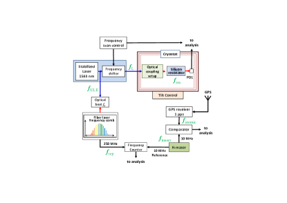
Overview of the apparatus. Fig. 1 (see also SupplementalMaterial-Cryoresonator2016-for-arxiv-tex-version ) shows the concept of the experiment, which is an extension of our previous work Wiens2014 . A silicon resonator is operated in a pulse-tube cooler (PTC) cryostat with Joule-Thomson (JT) cooling stage, providing a base temperature 1.5 K.
The silicon resonator is 25 cm long and consists of a cylindrical spacer and two optically contacted silicon mirror substrates SupplementalMaterial-Cryoresonator2016-for-arxiv-tex-version . Its linewidth is 2.0 kHz. The resonator is oriented horizontally and supported by wires inside a copper frame SupplementalMaterial-Cryoresonator2016-for-arxiv-tex-version . The supports’ symmetry is such that to first order the thermal expansion or length drift of the frame does not affect the resonator length.
In the frequency-scan interrogation technique (Fig. 1), the resonator’s TEM00 mode frequency is read out by a m (192 THz) external-cavity semiconductor laser (“Laser 1” in SupplementalMaterial-Cryoresonator2016-for-arxiv-tex-version ), which is frequency-stabilized to a room-temperature reference resonator (frequency ), having short-time fractional frequency instability and drift . During read-out, the laser frequency is offset to and is repeatedly scanned in time over a range of a few kHz across the silicon resonator resonance (line center frequency ). We record on the photodetector PD1 the power of the laser wave transmitted through the resonator, fit a lineshape model to each scan’s data, and extract the frequency offset . Simultaneously, the laser frequency corresponding to is measured by an erbium-fiber-laser-based femtosecond frequency comb, using a hydrogen maser () as reference. From these two measurements we obtain in units of . If was constant in time, the long-term variation of would mainly be given by the long-term variation of the length of the silicon crystal resonator spacer and (hypothetically) of the speed of light , , where , and are the resonance frequency, the spacer length, and the speed of light at a reference time , respectively.
Systematic effects. The experiment requires maintaining the operating parameters of the system as stable as possible. Several systematic effects were investigated.
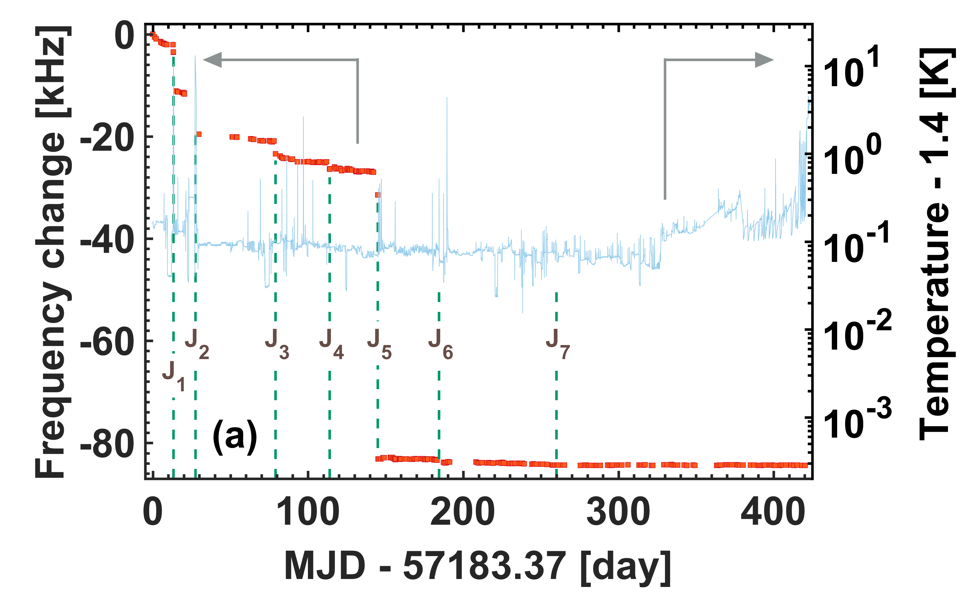
(1) Temperature: The cryostat was operated at its base temperature and no active temperature stabilization of the resonator was used, since it was unnecessary in the present context. Fig. 2 shows the temperature over a period of approximately 420 days with a typical peak-peak variation of 30 mK. The thermal sensitivity of the resonator being K at 1.5 K Wiens2014 ; Wiens2015 , this corresponds to a peak-peak fractional frequency deviation , which is not of importance here. On day 327 the operating temperature had to be raised to 1.55 K because of pressure increase in the JT stage. The calculated shift of 20 Hz was taken into account in the data analysis.
(2) Resonator deformation due to gravity: The sensitivity to tilt was measured to be rad and rad for tilt around the longitudinal and transverse axis, respectively. A tilt control system actuated two of the legs supporting the whole cryostat and reduced the tilt instability to a level below rad for integration times between 100 s and s.
The time variation of the local gravitational acceleration (tides, etc.) has a negligible effect on the resonator.
(3) Laser power: the laser power incident onto the resonator during line scan interrogation was 30 W or less, and was not actively stabilized. The power actually coupled into the resonator was 1.5% of the incident power. The power absorbed in the mirror substrate as the laser wave traverses it before entering the resonator and the power dissipated inside it could be detected via the concomitant resonator temperature changes. However, the corresponding thermal expansion is negligible. No effect on the resonator frequency could be detected directly.
(4) Vibrations: They are caused by the periodic (0.7 s) pulsing of the PTC and were characterized at room temperature by motion sensors attached to a plate close to the plate supporting the resonator). All spatial components of the acceleration have complex time evolutions (Fourier frequencies up to a few 100 Hz), and r.m.s. values of within a sensor band-width of 200 Hz. The accelerations cause resonator deformations that lead to fractional frequency shifts on the order of , periodic in time. We also performed an interferometric measurement of the periodic axial displacement of a second, identical silicon resonator inside the cryostat. The amplitude is approximately m.
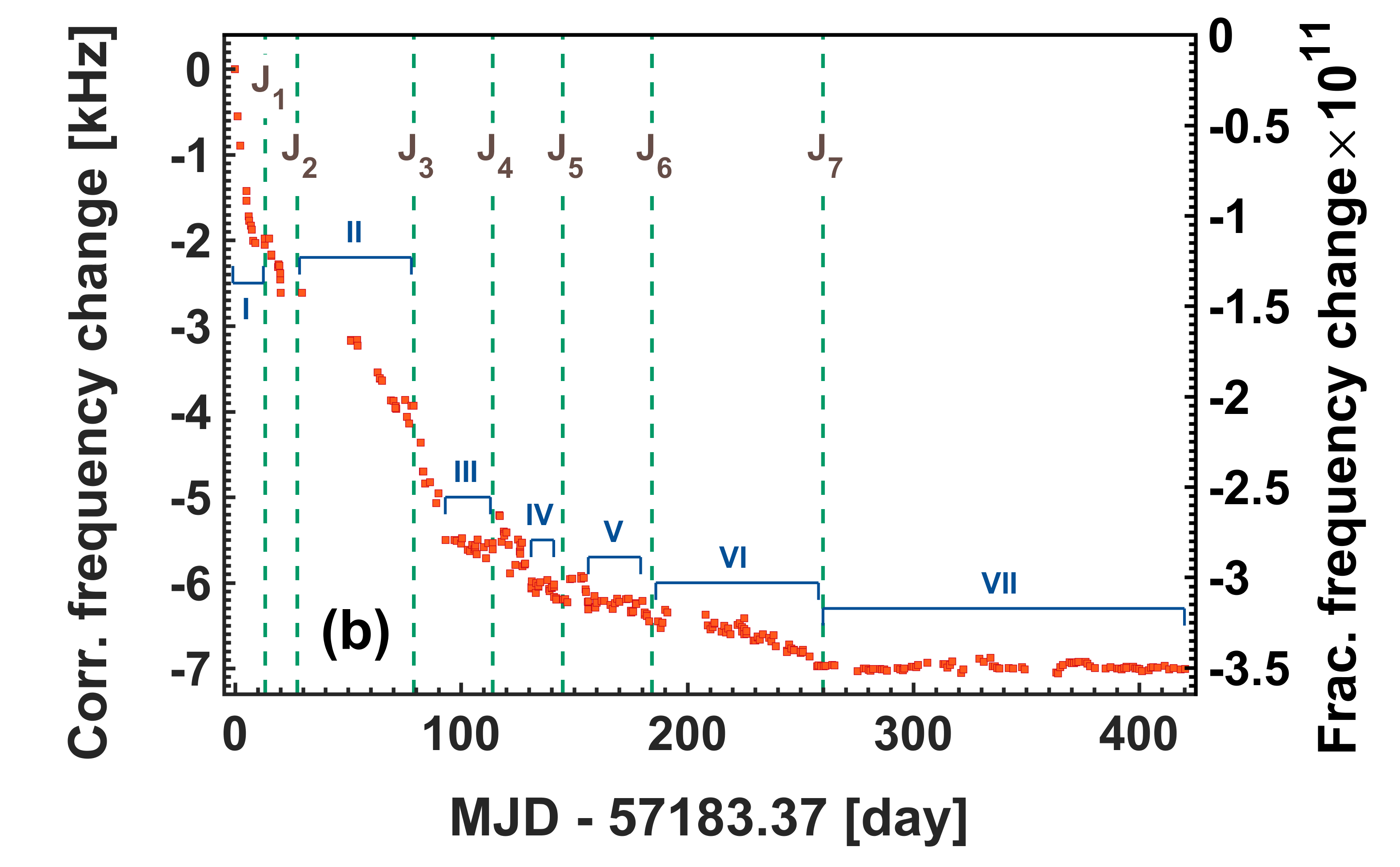
(5) Resonator interrogation by the frequency-scan technique: This technique (Fig. 1 and SupplementalMaterial-Cryoresonator2016-for-arxiv-tex-version ) leads to an Allan deviation of the line center frequency of at 1000 s integration time. During each frequency scan across the resonator mode, the signal recorded by detector PD1 is modulated (25% fractionally) in time in synchronism with the PTC pulsing, probably due to variations in coupling efficiency caused by the pulsing. The modulation is complex, with pulse-to-pulse variations. These signal disturbances lead to variations of the line centers frequencies fitted from individual scans. These variations are of the order (2 of the data) (gray bars in Fig. 3).
(6) Long-term effects of laser light. The laser intensity circulating in the resonator might cause photochemical or structural changes in the mirror coatings, with consequent resonator frequency change. We did not keep any laser frequency resonant for extended duration, in order to limit the irradiation of the mirrors SupplementalMaterial-Cryoresonator2016-for-arxiv-tex-version .
(7) Although it is known that maser frequency drift magnitude can be below s Matsakis2005 , it is fundamental to determine the influence of our particular maser on the optical frequency measurement. The maser was monitored by comparison with a 1-pulse-per-second signal delivered by GPS, which is derived from the international atomic time scale (TAI), defined by the cesium hyperfine transition. During the period day 225 - 264 the mean fractional drift was s. During the period day 293 - 415, the mean drift was s. This level is relevant in comparison with the drift of the resonator’s optical frequency with respect to the maser, , and thus must be accounted for. The error of is negligible for the present discussion.
Measurement of the resonator drift. Measurements were performed daily, when possible. In practice, each measurement of was taken as a time-average over several minutes, so as to suppress disturbances occurring over short time scales. The long-term behavior of the resonator frequency is depicted in Fig. 2(a). Frequency jumps to were caused by large temperature variations or by unintentional knocks on the cryostat. On day 149 , we deliberately knocked on the cryostat’s outer vacuum chamber, and observed 56 kHz frequency change. The frequency jump after was probably caused by a power shut-down SupplementalMaterial-Cryoresonator2016-for-arxiv-tex-version . To compensate for these jumps we shifted all frequency values after each jump by an amount equal to the difference between the last measurement before and first measurement after each jump. In Fig. 2(b) we display the resulting time series of the corrected frequency , the offsets for [,…,] being kHz.
We find that within 2 weeks after each disturbance to , the drift has dropped back to nominally zero. The data intervals III - VI are intervals between frequency jumps during which the resonator remained undisturbed. During these intervals, the drift rates were compatible with zero with upper limits /s. Interval VII is the period of longest undisturbed duration, 163 days. Starting with this interval, the frequency-scan interrogation technique was used. The data thus obtained is shown in Fig. 3. The variations of are mostly due to systematic effects (1) - (6); a possible additional contribution are long-term (time scale of days) maser frequency fluctuations, which we cannot independently identify via GPS, due to latter’s low stability.
Given the long overall measurement duration of 163 days we can assume that the variations are approximately randomly distributed. A time-linear fit of the optical frequency data yields /s (1 ). We then obtain the drift of the silicon resonator frequency with respect to atomic time as /s. The systematic effects disturbing the laser frequency scan data and the finite overall measurement time span determine the uncertainty of .
Interpretation. We interpret the zero drift in three ways: (a) as a test of LPI Turneaure1983 , (b) as a test for effects related to the expansion of the universe, and (c) as a test of the existence of space-time fluctuations. Local Lorentz Invariance is assumed to hold.
(a) One test of LPI is a null clock redshift test that tests for deviations from the clock-type-independence of the gravitational time dilation. It consists in measuring the ratio of the frequencies of two dissimilar clocks co-located at , as they are transported through a region of varying gravitational potential . The change of the frequency ratio is written as
| (1) |
where are the gravitational coupling constants of the two clock types, is the frequency ratio measured for the arbitrary reference value , and . If General Relativity holds, , independent of the type of clock. For two co-located clocks on Earth, is time-varying because of rotational and orbital motion. The data of Fig. 3 essentially corresponds to , the variation of the ratio of the resonator frequency and the frequency corresponding to the atomic unit ot time (delivered via GPS). A fit of Eq. 1 to the data yields for the clock coupling to the Sun’s gravitational potential, which is compatible with zero (the error given is the standard error). The upper bound is nearly equal to the result of ref. Tobar2010 (accounting for the result of ref. Bauch2002 ), where a cryogenic microwave sapphire oscillator (CSO) was used. However, our work achieved this result with a measurement duration of 5 months compared to 6 years.
(b) The second interpretation provides a limit for (hypothetical) linear-in-time effects on measuring rods, caused by the expansion of the universe, if General Relativity is violated. Ref. Kopeikin2015 discusses that such an effect is absent if General Relativity holds. To arrive at such a bound we first discuss how bounds of LPI violation and time-variation of fundamental constants contribute.
We assume that the LPI bound of refs. Bauch2002 ; Tobar2010 , , holds also for standing-wave optical resonators, like the one used here. This implies that during the interval from day 258 to day 420 the mean resonator drift from a LPI violation is smaller than s. Note that ref. Tobar2010 derives the LPI bound from the CSO’s annual frequency modulation amplitude only. The CSO’s frequency drift, s, was removed before data analysis, therefore the value of is independent of any expanding-universe effect. Furthermore, we recall that within conventional physics, (where is derived from the Cs hyperfine transition) can in principle be expressed in terms of the fine-structure constant, , nuclear parameters, the number of lattice planes in the silicon resonator, and numerical coefficients. The current experimental limits for the drifts of these constants and parameters, derived from comparisons between atomic clocks Uzan2011 , lead to a bound much smaller than our and .
Thus, the results of and can be combined to set the bound /s for the magnitude of linear-in-time drifts of the length of a solid, when measured by clocking the propagation of electromagnetic waves across its length. This is a factor 82 smaller than the natural scale , and thus rules out any effect that is of first order in .
(c) Space-time fluctuations (or “foam”) is a concept that describes the possibility that repeated measurements of a particular time interval or a particular distance do not give a constant result but fluctuate due to fundamental reasons. The measurement of the resonator frequency performed here ultimately corresponds to a measurement of a particular distance (the mirror spacing ), in units of the wavelength of an electromagnetic wave resonant with the cesium hyperfine transition. Simple models for the noise power spectral density ( is the fluctuation frequency) of the fractional length fluctuations have been introduced Ng2003 , leading to flicker frequency noise, or random-walk frequency noise, . Experiments are required to place upper limits on and .
We compare our time series of with simulated time series generated from flicker and random walk noise and therefrom deduce and . These limits are weaker than our previous measurements Schiller2004 ; Chen2016 , but are here established from data at significantly lower Fourier frequencies, Hz.
Summary and Outlook. In this work we have demonstrated that a silicon crystal exhibits an extremely small length drift at cryogenic temperature. The mean fractional drift measured during a time span of 5 months of nearly undisturbed operation was /s. This is the lowest value measured so far for resonators, to the best of our knowledge. The uncertainty of the value is due to the systematic effects caused by the cryostat cooler and by the finite measurement time span. Both aspects could be improved in the future. The measurement rules out local consequences of the expansion of the universe which are of order of the Hubble constant . In addition, the data provides the best upper limit for violations of Local Position Invariance for an optical resonator and for the existence of space-time fluctuations with frequencies in the Hz-range.
To illustrate the smallness of the drift, we note that the upper limit for , the positive value /s, is consistent with a shortening of the optical path length in the resonator. If this were caused by deposition of molecules on the mirrors, the deposition rate would be one molecular layer on each mirror every years, or approximately 30 molecules/s within the laser beam cross section (1 mm diameter).
The cryogenic silicon resonator could potentially be used as a local oscillator with performance beyond that of hydrogen masers and with autonomous operation. Future progress in cryostat technology may eventually allow suppressing the vibrations to a sufficiently low level so that a silicon resonator exhibits sub- fractional frequency instability, on all time scales, in addition to negligible drift. Until this potential is realized, another suggested implementation consists of a cryogenic silicon resonator combined with an improved version of the ULE-resonator-stabilized laser used here SupplementalMaterial-Cryoresonator2016-for-arxiv-tex-version . State-of-the-art ULE resonators are in principle capable of providing frequency instability at level for integration times of up to 1000 s (see, e.g. Jiang2011 ; Nichloson2012 ; Haefner2015 ), but this requires eliminating their drift, of typical magnitude /s. The drift would be determined by periodic comparison with the silicon resonator and would be compensated by a feed-forward scheme. Our work suggests that the proposed solution will be robust and practical, since we showed uninterrupted operation of the resonator for 12 months without serious problems.
Acknowledgements.
We thank I. Ernsting, Q.-F. Chen, U. Rosowski, D. Iwaschko, P. Dutkiewich, and R. Gusek for valuable contributions, and M. Schioppo for comments. This work has been funded by ESA project no. 4000103508/11/D/JR and by DFG project Schi 431/21-1. E.W. and S.S. contributed equally to this work.Corresponding author: step.schiller@hhu.deReferences
- (1) J.-P. Uzan, Varying constants, gravitation and cosmology, Living Rev. Relativity 14 (2011) 2.
- (2) J.P. Turneaure, C.M. Will, B.F. Farrell, E.M. Mattison, R.F.C. Vessot, Test of principle of equivalence by a null red-shift experiment, Phys. Rev. D 27 (1983) 1705.
- (3) C.Braxmaier, H.Müller, O. Pradl, J. Mlynek, A. Peters, S. Schiller, Test of relativity using a cryogenic optical resonator, Phys. Rev. Lett. 88 (2002) 010401.
- (4) H. Müller, S. Herrmann, C. Braxmaier, S. Schiller, A. Peters, Modern Michelson-Morley experiment using cryogenic optical resonators, Phys. Rev. Lett. 91 (2003) 020401.
- (5) P. Antonini, M. Okhapkin, E. Göklü, S. Schiller, Test of constancy of speed of light with rotating cryogenic optical resonators, Phys. Rev. A 71 (2005) 050101(R).
- (6) S. Schiller, C. Lämmerzahl, H. Müller, C. Braxmaier, S. Herrmann, A. Peters, Experimental limits for low-frequency space-time fluctuations from ultrastable optical resonators, Phys. Rev. D 69 (2004) 027504.
- (7) M. E. Tobar, P. Wolf, S. Bize, G. Santarelli, V. Flambaum, Testing local lorentz and position invariance and variation of fundamental constants by searching the derivative of the comparison frequency between a cryogenic sapphire oscillator and hydrogen maser, Physical Review D 81 (2010) 022003
- (8) J. Millo, M. Abgrall, M. Lours, E. M. L. English, H. Jiang, J. Guena, A. Clairon, M. E. Tobar, S. Bize, Y. Le Coq, G. Santarelli, Ultralow noise microwave generation with fiber-based optical frequency comb and application to atomic fountain clock, Applied Physics Letters 94 (2009) 141105.
- (9) T. Kessler, C. Hagemann, C. Grebing, T. Legero, U. Sterr, F. Riehle, M. J. Martin, L. Chen, J. Ye, A sub-40-mHz-linewidth laser based on a silicon single-crystal optical cavity, Nature Photonics 6 (2012) 687.
- (10) J. G. Hartnett, N. R. Nand, C. Lu, Ultra-low-phase-noise cryocooled microwave dielectric-sapphire-resonator oscillators, Appl. Phys. Lett. 100 (2012) 183501.
- (11) J. G. Hartnett, C. R. Locke, E. N. Ivanov, M. E. Tobar, P. L. Stanwix, Cryogenic sapphire oscillator with exceptionally high long-term frequency stability, Appl. Phys. Lett. 89 (2006) 203513.
- (12) S. Seel, R. Storz, G. Ruoso, J. Mlynek, S. Schiller, Cryogenic Optical Resonators: A new tool for laser frequency stabilization at the 1 Hz level, Phys. Rev. Lett. 78 (1997) 4741.
- (13) R. Storz, C. Braxmaier, K. Jäck, O. Pradl, S. Schiller, Ultrahigh long-term dimensional stability of a sapphire cryogenic optical resonator, Opt. Lett. 23 (1998) 1031.
- (14) J.-P. Richard, J. J. Hamilton, Cryogenic monocrystalline silicon Fabry-Perot cavity for the stabilization of laser frequency, Rev. Sci. Instrum. 62 (1991) 2375.
- (15) E. Wiens, Q. Chen, I. Ernsting, H. Luckmann, A. Y. Nevsky, U. Rosowski, S. Schiller, A silicon single-crystal cryogenic optical resonator, Opt. Lett. 39 (2014) 3242.
- (16) E. Wiens, Q. Chen, I. Ernsting, H. Luckmann, A. Y. Nevsky, U. Rosowski, S. Schiller, Silicon single-crystal cryogenic optical resonator: erratum, Opt. Lett. 40 (2015) 68.
- (17) C. Hagemann, C. Grebing, C. Lisdat, S. Falke, T. Legero, U. Sterr, F. Riehle, M. J. Martin, J. Ye, Ultra-stable laser with average fractional frequency drift rate below 5/s, Opt. Lett. 39 (2014) 5102.
- (18) See Supplemental Material on the PRL website for details of the setup and experimental procedures.
- (19) D. Matsakis, P. Koppang, R. M. Garvey, The long-term stability of the U.S Naval Observatory’s masers, in: Proceedings of the 36th Annual Precise Time and Time Interval Systems and Applications Meeting, Washington, D.C., December 2004, 2005, pp. 411–422.
- (20) A. Bauch, S. Weyers, New experimental limit on the validity of local position invariance, Phys. Rev. D 65 (2002) 081101.
- (21) S. M. Kopeikin, Optical cavity resonator in an expanding universe, Gen Rel Grav 47:5 (2015).
- (22) Y. J. Ng, Selected topics in Planck-scale physics, Modern Physics Letters A 18 (2003) 1073.
- (23) Q. Chen, E. Magoulakis, S. Schiller, High-sensitivity crossed-resonator laser apparatus for improved tests of lorentz invariance and of space-time fluctuations, Phys. Rev. D 93 (2016) 022003.
- (24) Y. Y. Jiang, A. D. Ludlow, N. D. Lemke, R. W. Fox, J. A. Sherman, L.-S. Ma, C. W. Oates, Making optical atomic clocks more stable with 10-16-level laser stabilization, Nature Photonics 5 (2011) 158.
- (25) T. L. Nicholson, M. J. Martin, J. R. Williams, B. J. Bloom, M. Bishof, M. D. Swallows, S. L. Campbell, J. Ye, Comparison of two independent Sr optical clocks with stability at s, Phys. Rev. Lett. 109 (2012) 230801.
- (26) S. Häfner, S. Falke, C. Grebing, S. Vogt, T. Legero, M. Merimaa, C. Lisdat, U. Sterr, fractional laser frequency instability with a long room-temperature cavity, Optics Lett. 40 (2015) 2112–2115.
- (27) C. Braxmaier, O. Pradl, H. Müller, B. Eiermann, A. Peters, J. Mlynek, S. Schiller, Fiber-coupled and monolithic cryogenic optical resonators, in: 2000 Conf. on Precision Electromagnetic Measurements Digest, IEEE Cat. No. 00CH37031, pp. 192–193.