Plasma Dipole Oscillation Excited by Trapped Electrons Leading to Bursts of Coherent Radiation
Abstract
Plasma dipole oscillation (PDO) depicted as harmonic motion of a spatially localized block of electrons has, until now, been hypothetical. In practice, the plasma oscillation occurs always as a part of a plasma wave. Studies on radiation burst from plasmas have focused only on coupling of the plasma wave and electromagnetic wave. Here we show that a very-high-field PDO can be generated by the electrons trapped in a moving train of potential wells. The electrons riding on the potential train coherently construct a local dipole moment by charge separation. The subsequent PDO is found to persist stably until its energy is emitted entirely via coherent radiation. In our novel method, the moving potentials are provided by two slightly-detuned laser pulses colliding in a non-magnetized plasma. The radiated energy reaches several millijoules in the terahertz spectral region. The proposed method provides a way of realizing the PDO as a new radiation source in the laboratory. PDO as a mechanism of astrophysical radio-bursts is discussed.
pacs:
52.59.Ye, 52.25.Os, 52.65.RrPlasma oscillations are usually described as in-phase motion of a spatially-localized block of electrons (plasma dipole oscillations, PDO). However, so far the PDO has been hypothetical; there has been no efficient method to generate it, and its stability is not known. In practice, plasma oscillations always occur as parts of a travelling plasma wave, which is a collection of infinitesimal plasma oscillators with different phases. A plasma wave in a non-magnetized, homogeneous plasma cannot emit an electromagnetic wave, since, as there is no crossing point of their dispersion curves, the energy exchange between those waves is prevented. Hence, previous studies have focused on finding mechanisms for how the electrostatic plasma wave is coupled to an electromagnetic wave in inhomogeneous or magnetized plasmas, to explain the observed radio-bursts from the solar corona reid ; boyd ; sturrock ; melrose ; yoon , the terahertz, or higher-frequency emission from laboratory plasmas chinfatt ; hamster ; yoshii ; yugami ; sheng ; jjkim ; gopal ; cho ; liao ; liao2 ; bezzerides ; teubner ; quere ; ijkim . Known wave-wave coupling mechanisms include linear mode conversion and coherent wake emission sheng ; quere , parametric plasmon coalescence melrose ; teubner , and Cherenkov wake emission yoshii ; yugami . However, the PDO has not been explored as a mechanism of the radiation emission.
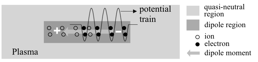
In this Letter, we show, for the first time, that a very high-field PDO can be generated without relying on external magnetic or electric fields. Also we show that the PDO persists stably until all of its energy is emitted via a burst of coherent radiation, which is distinct from the emission by conventional wave-wave coupling. The mechanism to generate a PDO, revealed first here, is building up a dipole moment by electrons trapped in a spatially localized, moving train of potential wells. The trapped electrons, riding on the potential train, are displaced to generate a dipole field by charge separation between the displaced electrons and the remaining ions (Fig. 1). Later, as the moving potentials diminish, the dipole is released to commence plasma oscillation, which serves as the dipole radiator. As the electron trapping is prevalent in plasmas of diverse scales, the PDO may be relevant to various known observations of the radio-bursts from space (e.g., the coronal type III bursts reid ), or terahertz bursts from laser-solid interactions liao ; liao2 .
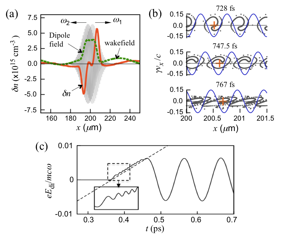
As a novel method to produce the moving potential train, here we consider the ponderomotive (PM) potential associated with the beat wave of two slightly-detuned laser pulses that collide in the plasma. In the region where the pulses overlap, electrons are trapped by the PM potentials that moves in the direction of the higher frequency pulse at a phase velocity , where and are the angular frequencies and wavenumbers of the laser pulses, respectively. The “displacement-release” process for this system is numerically demonstrated using one-dimensional (1D) particle-in-cell (PIC) simulations (Fig. 2). The electron displacement yields a pair of oppositely-charged layers (Fig. 2a, solid orange), which produces a dipole field (Fig. 2a, dashed green). The distance between the layers is comparable with the pulse width. For obliquely colliding pulses, this distance is also controlled by the collision angle. The electron phase-space distributions close to the centre of the pulse collision (Fig. 2b), demonstrate that the trapped electrons co-move with the PM potential. As the trapped electrons move with constant , the dipole electric field at the centre increases linearly over time (Fig. 2c). The small, fast oscillation at the bounce frequency during the linear growth (Fig. 2c, inset) confirms that the field growth is led by trapped electrons. As will be shown, the emitted radiation from the PDO generated by colliding pulses exhibits a unique spectrum that includes both a super-continuum and a narrow-bandwidth peak. The energy of the radiation reaches several millijoules in the terahertz spectral region, making it suitable for applications that require strong terahertz fields.
The dipole field can be generated in a similar way by colliding chirped pulses, which is easy to realize in practice vieux . In this case, in general, the growth of the dipole field is not linear with time. Note that the large charge separation is a result of coherent displacement of the trapped electrons in multiple PM potential wells, which grow in numbers as the overlap of the laser pulses increases. On either side of the dipole field, there is a low-amplitude wakefield generated by the laser pulses before collision.
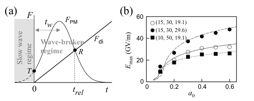
The maximum displacement of electrons at the centre can be calculated explicitly using a force-balance model (Fig. 3a). When the normalized peak amplitude of the laser pulses, is sufficiently high, the PM force increases faster, at an early stage, than the restoring force of the dipole field, thereby driving the electron displacement. Later, when the PM force drops below the restoring force, electron displacement stops and the electron dipole is released (Fig. 3a, point ). When the time of the release is denoted by (Fig. 3a), the maximum dipole field is given by
| (1) |
where , i.e. the slope of the dipole field growth. With an assumption that locally all the electrons are trapped, from Gauss’s law,
| (2) |
where is the charge of a single electron, is the vacuum permittivity, , and . This model predicts that, by increasing and the pulse duration , can be delayed considerably, leading to very large , although the rate of increase of becomes very slow for relativistic laser intensities ().
The growth of led by the trapped electrons should be preceded by wavebreaking of the slow plasma wave, which is driven by the initial weak portion of the PM force (Fig. 3a). The electron trapping follows the wavebreaking with almost no delay, since the plasma wave grows rapidly. To determine , we first calculate , which is defined by time from the start of wavebreaking to that of the maximum PM force. Before wavebreaking, electrons are driven into harmonic motion by the PM force, i.e., , where is the plasma frequency, the normalized amplitude of the laser pulses, and the electron displacement. For longitudinally Gaussian laser pulses, , where . Note that the wavebreaking occurs at . With (slow plasma wave), where is the oscillation amplitude, the equation of motion yields
| (3) |
When , wavebreaking occurs due to the change in ordering of electrons dawson . In Eq. (3), we assume increases rapidly until wavebreaking, so (verified by PIC simulations), which is opposite to the regular assumption of the slowly-varying envelope models, e.g., hurprl . can be calculated using a convolution integral of the Green’s function and source term of Eq. (3) for . From the wavebreaking condition,
| (4) |
The release time can be obtained by balancing the ensemble-averaged PM force with the restoring force (). When the frequency difference of the laser pulses is constant, , leading to
| (5) |
where is related to the ensemble average of the PM force exerted on electrons scattered inside each PM potential segment. The ensemble average is equivalent to the time-average of the PM force exerted on a single electron during one bounce cycle (i.e., , where and are the amplitude and centre of the bouncing motion, respectively), leading to , where is the zero’th order Bessel function. From and , . from numerical solutions of Eqs. (1), (2), (4), and (5) along with agrees well with 1D PIC simulation data for a diverse range of parameters (Fig. 3b). Note that although we considered the electrons located initially at to obtain those equations, they are still valid for nearby electrons for short-enough driving pulses.
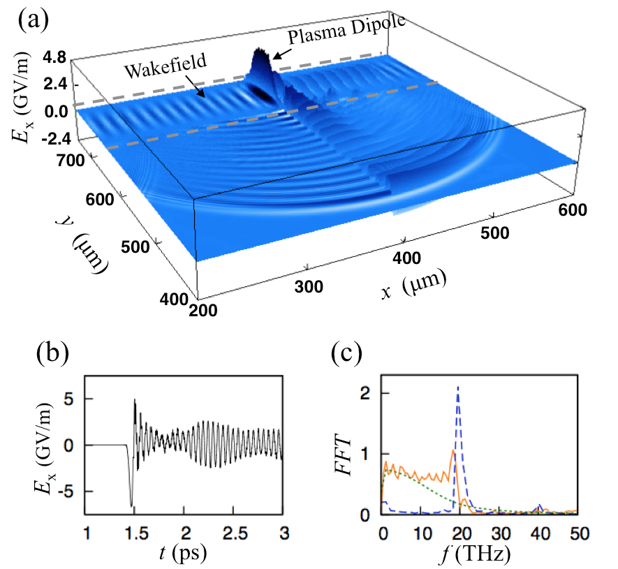
To determine the radiation emission pattern from the PDO, we have performed two-dimensional (2D) PIC simulations. We present the results for THz (), , ( THz), , fs, and spot radius 40 m (Fig. 4a). The laser pulses counter-propagate along the -direction and collide with zero collision angle at the centre of a plasma strip. The high amplitude dipole oscillation emits bi-directional radiation (only one part is shown). The peak amplitude of the radiation field reaches 5 GV/m determined at 60 m from the centre of the dipole (Fig. 4b). When the laser pulses collide deep in a bulk plasma instead of a strip, the duration of the burst is prolonged with the leading peak amplitude being lowered. The radiation from the travelling wakefields observed on both sides of the dipole is very weak because of destructive interference. The radiation field increases linearly over ps during the pulse collision, and oscillates subsequently over ps (Fig. 4b). Interestingly, monochromatic radiation at is emitted even after the decay of the dipole radiation (Fig. 4b, ps; 4c, dashed blue); this persisting emission is due to the collision of the travelling wakefields. Appearance of this oscillation in the tail does not show consistent dependence on laser and plasma parameters: it is sometimes prominent, as in the given case, but can also be negligible even under similar parameters. The spectral properties are noteworthy: the spectrum of the radiation from ps to the first decay ( 2 ps) contains both a spectral continuum and a narrow-band peak at (Fig. 4c, solid orange). The low frequency part in the continuum (Fig. 4c, dotted green) results mostly from the first half cycle (Fig. 4b, ps), which corresponds to the linearly growing phase of the dipole field. This implies that the continuous spectrum can be controlled by frequency chirp of the driving pulses.
The radiation amplitude in 2D space can be deduced from the 1D model of the dipole field. In 2D polar coordinates, the electric field of radiation from 2D dipole moment is represented by
where is radial distance, is polar angle, is the radiation frequency (), and is the electric polarization. As the charge is separated approximately with over , , where is determined by Eq. (1) at each . In 2D, the dipole field and polarization are related by . Then we obtain
| (6) |
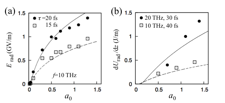
Equation (6) agrees well with 2D simulation data for and (Fig. 5a). In these simulations, the spot radius of the driver pulses is set to 40 and the plasma strip is 80 wide.
To estimate the radiation energy, we assume all the initial dipole field energy is converted to radiation energy . Then, in 2D,
| (7) |
Predictions of Eq. (7) agree well with results of 2D PIC simulations at and 20 THz (Fig. 5b). The reasonable agreement implies that virtually all of the initial dipole energy is converted into radiation. Total radiation energy in 3D can be approximated by multiplying the lateral dimension (-length) of the dipole to Eq. (7). To maximize the emission energy, the lateral dimension should be made as large as possible by using highly elliptical driving pulses. High-power elliptical laser beams with an eccentricity of more than an order of magnitude are readily available shim ; laskin . Assuming a laser spot, the total energy of the dipole radiation is expected to reach a few millijoules (Fig. 5b). This energy can be increased further by increasing the driving pulse intensity. Also the system can be optimized by adjusting the frequency chirping or the collision angle of the laser pulses.
PDO can be relevant to emission from diversely different plasma systems. As the ejection of energetic electron beams (e.g., by magnetic reconnection egedal ) is prevalent in astrophysical plasmas (e.g., in the solar corona reid ), pairs of colliding beams could possibly generate dipole moments by trapping electrons in plasma waves, which grow from stream instabilities. Similar dipole radiation in the terahertz spectral region may have been produced (but overlooked) in laser-solid interactions liao ; liao2 , where the reflected pulse overlaps the incident pulse obliquely in the underdense plasma expanded from the surface of the solid. In this system, the Doppler-shift caused by the moving reflection surface of the plasma can provide the reflected and incident pulses with the necessary frequency-detuning. The PDO driven by colliding pulses can also be used for a diagnostics of local plasma density; as the radiation spectrum of the PDO peaks at the plasma frequency, the radiation contains the information of the local plasma density at the position of the pulse collision.
The mechanism of dipole generation here is distinct from Ref. cho , where a weak dipole field is generated by a small nonlinear current that is disrupted by trapped electrons. In contrast, here the trapped electrons generate a very strong dipole field beyond wavebreaking; previous limitations in growth of the dipole field are circumvented. Moreover, unlike Ref. cho , the radiation can be directly emitted from the dipole without relying on an external magnetic field. The mechanism we propose is also different from coalescence of two plasmons melrose ; teubner , which generate second harmonic radiation. In our method, the fundamental harmonic radiation is dominant. An oscillating plasma surface bulanov ; lichters ; norreys ; dromey2 ; dromey3 is also a kind of localized plasma oscillation, but it is limited to a relatively steep plasma-vacuum interface. Moreover, differently from the PDO, it acts as a reflector for high harmonic generation, rather than as a radiation emitter. Particle trapping by counter-propagating pulses was studied in the long-pulse (both or one of the them) regime hurprl ; sheng2 ; shvets ; shvets2 , but a localized PDO and the radiation from that were not perceived.
In conclusion, we have investigated the generation of localized plasma dipole oscillations (PDO) in non-magnetized plasmas by trapped electrons in a train of moving potential wells. As an efficient way to provide the necessary potential train, we considered the ponderomotive potentials generated by the beat of colliding laser pulses. It was shown that the PDO can persist stably until its entire energy is emitted via coherent radiation burst. Results of 2D PIC simulations suggest that the radiation energy can reach several millijoules in the terahertz spectral region, which may lead to applications in terahertz sciences where very strong fields are required. The force-balance model predicts that the radiation energy can be increased considerably by increasing the driving pulse intensity. Also, the pulse duration, frequency chirping, and collision angle of the pulses can be further optimized. The suggested method can be used for diagnostics of local plasma density. The stably-persisting PDO is relevant to a radiation mechanism in diverse scales of plasma and over a large wavelength range, such as the laser-solid interactions and radiation bursts from astrophysical plasmas.
Acknowledgements.
This work was supported by the Basic Science Research Program through the National Research Foundation (NRF) of Korea funded by the Ministry of Science, ICT and Future Planning (Grant number NRF-2014M1A7A1A01030175 and NRF-2016R1A5A1013277). For the simulations, we were supported by the PLSI supercomputing resources of the Korea Institute of Science and Technology Information. DAJ and BE were supported by the UK Engineering and Physical Sciences Council Grants no. EP/J018171/1 and EP/N028694/1, the ECs LASERLAB-EUROPE (grant agreement no. 284464, Seventh Framework Programme), EuCARD-2 (grant no. 312453, FP7) and the Extreme Light Infrastructure (ELI) European Project. We used VisIt for visulisation of 2D data (https://wci.llnl.gov/simulation/computer-codes/visit). We acknowledge Prof. D. Ryu at UNIST and Prof. Y.U. Jeong at KAERI for useful discussions and comments.References
- (1) H.A.S. Reid and H. Ratcliffe, Res. Astronomy and Astrophys. 14, 773 (2014).
- (2) T.J.M. Boyd, Phys. Fluids 7, 59 (1964).
- (3) P.A. Sturrock, R.H. Ball, and D.E. Baldwin, Phys. Fluids 8, 1509 (1965).
- (4) D.B. Melrose, Space Sci. Rev. 26, 3 - 38 (1980).
- (5) P.H. Yoon, Phys. Plasmas 2, 537 - 548 (1995).
- (6) C. Chin-Fatt and H.R. Griem, Phys. Rev. Lett. 25, 1644 (1970).
- (7) H. Hamster, A. Sullivan, S. Gordon, W. White, and R.W. Falcone, Phys. Rev. Lett. 71, 2725 (1993); Phys. Rev. E 49, 671 (1994).
- (8) J. Yoshii, C. H. Lai, T. Katsouleas, C. Joshi, W. B. Mori, Phys. Rev. Lett. 79, 4194 (1997).
- (9) N. Yugami, T. Higashiguchi, H. Gao, S. Sakai, K. Takahashi, H. Ito, Y. Nishida, and T. Katsouleas, Phys. Rev. Lett. 89, 065003 (2002).
- (10) Z.-M. Sheng, K. Mima, J. Zhang, and H. Sanuki, Phys. Rev. Lett. 94, 095003 (2005).
- (11) J.J. Kim, D.G. Jang, M.S. Hur, H. Jang, and H. Suk, J. Phys. D: Appl. Phys. 45, 395201 (2012).
- (12) A. Gopal, S. Herzer, A. Schmidt, P. Singh, A. Reinhard, W. Ziegler, D. Brömmel, A. Karmakar, P. Gibbon, U. Dillner, T. May, H-G. Meyer, and G.G. Paulus, Phys. Rev. Lett. 111, 074802 (2013).
- (13) M.H. Cho, Y.-K. Kim, H. Suk, B. Ersfeld, D.A. Jaroszynski, and M.S. Hur, New J. Phys. 17, 043045 (2015).
- (14) G.Q. Liao,Y.T. Li, C. Li, L.N. Su, Y. Zheng, M. Liu, W.M. Wang, Z.D. Hu, W.C. Yan, J. Dunn, J. Nilsen, J. Hunter, Y. Liu, X. Wang, L.M. Chen, J.L. Ma, X. Lu, Z. Jin, R. Kodama, Z.M. Sheng, and J. Zhang, Phys. Rev. Lett. 114, 255001 (2015).
- (15) G.-Q. Liao, Y.-T. Li, Y.-H. Zhang, H. Liu, X.-L. Ge, S. Yang, W.-Q. Wei, X.-H. Yuan, Y.-Q. Deng, B.-J. Zhu, Z. Zhang, W.-M. Wang, Z.-M. Sheng, L.-M. Chen, X. Lu, J.-L. Ma, X. Wang, and J. Zhang, Phys. Rev. Lett. 116, 205003 (2016).
- (16) B. Bezzerides, R.D. Jones, and D.W. Forslund, Phys. Rev. Lett. 49, 202 (1982).
- (17) U. Teubner, D. Altenbernd, P. Gibbon, E. Förster, A.Mysyrowicz, P. Audebert, J.-P. Geindre, J.C. Gauthier, R. Lichters, J. Meyer-ter-Vehn, Opt. Comm. 144, 217 - 221 (1997).
- (18) F. Quéré, C. Thaury, P. Monot, S. Dobosz, Ph. Martin, J.-P. Geindre, and P. Audebert, Phys. Rev. Lett. 96, 125004 (2006).
- (19) I.J. Kim, K.H. Pae, C.M. Kim, H.T. Kim, H.Yun, S.J. Yun, J.H. Sung, S.K. Lee, J.W. Yoon, T.J. Yu, T.M. Jeong, C.H. Nam, and J. Lee, Nat. Comm. 3:1231, (2012).
- (20) G. Vieux, B. Ersfeld, J.P. Farmer, M.S. Hur, R.C. Issac, and D.A. Jaroszynski, Appl. Phys. Lett. 103, 121106 (2013).
- (21) J.M. Dawson, Phys. Rev. 113, 383 (1959).
- (22) M.S. Hur, R.R. Lindberg, A.E. Charman, J.S. Wurtele, and H. Suk, Phys. Rev. Lett. 95, 115003 (2005).
- (23) B. Shim, S.E. Schrauth, L.T. Vuong, Y. Okawachi, and A.L. Gaeta, Opt. Expr. 19, 9139 (2011).
- (24) A. Laskin and V. Laskin, SPIE Proceedings OP2013-8843-12 (2013).
- (25) J. Egedal, W. Daughton, and A. Le, Nat. Phys. 8, 321 (2012).
- (26) S.V. Bulanov, N.M. Naumova, and F. Pegoraro, Phys. Plasmas 1, 745 - 757 (1994).
- (27) R. Lichters, J. Meyer-ter-Vehn, and A. Pukhov, Phys. Plasmas 3, 3425 (1996).
- (28) P.A. Norreys, M. Zepf, S. Moustaizis, A.P. Fews, J. Zhang, P. Lee, M. Bakarezos, C.N. Danson, A. Dyson, P. Gibbon, P. Loukakos, D. Neely, F.N. Walsh, J.S. Wark, and A.E. Dangor, Phys. Rev. Lett. 76, 1832 (1996).
- (29) B. Dromey, S. Kar, C. Bellei, D.C. Carroll, R.J. Clarke, J.S. Green, S. Kneip, K. Markey, S.R. Nagel, P.T. Simpson, L. Willingale, P. McKenna, D. Neely, Z. Najmudin, K. Krushelnick, P.A. Norreys, and M. Zepf, Phys. Rev. Lett. 99, 085001 (2007).
- (30) B. Dromey, D. Adams, R. Hörlein, Y. Nomura, S.G. Rykovanov, D.C. Carroll, P.S. Foster, S. Kar, K. Markey, P. McKenna, D. Neely, M. Geissler, G.D. Tsakiris, and M. Zepf, Nat. Phys. 5, 146 (2009).
- (31) Z.-M. Sheng, K. Mima, Y. Sentoku, M.S. Jovanović, T. Taguchi, J. Zhang, and J. Meyer-ter-Vehn, Phys. Rev. Lett. 88, 055004 (2002).
- (32) G. Shvets, N.J. Fisch, A. Pukhov, and J. Meyer-ter-Vehn, Phys. Rev. E 60, 2218 (1999).
- (33) G. Shvets, N.J. Fisch, A. Pukhov, and J. Meyer-ter-Vehn, Phys. Rev. Lett. 81, 4879 (1998).