Exciton-Polariton Flows in Cross-Dimensional Junctions
Abstract
We study the nonequilibrium exciton-polariton condensation in 1D to 0D and 1D to quasi-2D junctions by means of non-resonant spectroscopy. The shape of our potential landscape allows to probe the resonant transmission of a propagating condensate between a quasi-1D waveguide and cylindrically symmetric states. We observe a distinct mode selection by varying the position of the non-resonant pump laser. Moreover, we study the the case of propagation from a localized trapped condensate state into a waveguide channel. Here, the choice of the position of the injection laser allows us to tune the output in the waveguide. Our measurements are supported by an accurate Ginzburg-Landau modeling of the system shining light on the underlying mechanisms.
Introduction.— Strong coupling between microcavity photons and quantum well excitons leads to the formation of exciton-polaritons which can in turn form coherent quantum states Kasrpzak2006 mediated by bosonic stimulated scattering Savvidis2000 . Polariton states are of macroscopic size and can propagate coherently over large distances Nelsen2013 Fischer2014 . Due to their hybrid nature, polaritons in microstructures can be conveniently confined Schneider2017 and manipulated Wertz2010 via their excitonic or photonic part. Reconfigurable repulsive potentials can be introduced in these systems through a local exciton reservoir generated by a non-resonant laser. For these reasons, polaritons have emerged as a versatile platform to study the behavior of a quantum fluid of light Carusotto2013 and as a promising candidate for fast modulated Miller2010 optical on-chip logic circuits Liew2010 in a solid state environment. Progresses in this field have yielded logic elements such as an all-optical router Flayac2013 Marsault2015 , a transistor Gao2012 Ballarini2013 , an amplifier Wertz2012 Niemitz2016 , or a Mach-Zehnder interferometer Sturm2014 . A precise and deterministic control over the confined polariton modes and polariton propagation into waveguides is essential for an all optical circuit.
In this work, we generate an exciton-polariton condensate in an AlGaAs/AlAs Fabry-Pérot microcavity via nonresonant injection and investigate the spatial spread at the interface of potentials of different dimensionality. These potentials are composed of cylindrical traps connected to a waveguide wire. In such ”lollipop”-shaped potential landscapes, we generate a condensate via nonresonant pumping in the wire section, which expands over the device. Furthermore we demonstrate the possibility to feed into the waveguide wire from the trap while controlling the energy of the injecting mode by spatial positioning of the laser spot.
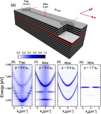
Experiment.— We investigate the spreading of polariton condensates in lollipop-shaped potentials by means of realspace imaging as the polariton wave functions in confined systems are directly observable Kalevich2015 Nardin2010 . The potential itself is generated by a well controlled local elongation of the cavity layer thickness Daif2006 . The microcavity grown by molecular beam epitaxy [see Fig. 1(a)] consists of an AlAs--cavity surrounded by 37 (32) bottom (top) AlGaAs/AlAs distributed Bragg reflector (DBR) mirror pairs while the active media comprises two stacks of four nm GaAs quantum wells distributed at the optical antinodes inside the cavity layer and at the first DBR interface [red color coded in Fig. 1(a)].
By patterning the nm thick GaAs-layer on top of the cavity layer in an etch-and-overgrowth step, we introduce an attractive photonic potential with a height-difference of about nm which amounts to about meV. More details on the process and further sample details concerning mode confinement and condensation properties can be found elsewhere Winkler2015 . As exciton-polaritons are hybrid light-matter quasiparticles, the photonic potential yields a trapping potential for polaritons Boiko2008 Kaitouni2006 , which also supports polariton condensation Winkler2015 .
Here we carry out measurements of three devices which differ in the in-plane geometry of the potential. Exemplarily a sketch of the 10-µm-dumbbell potential is depicted in Fig. 1(a): It is composed of two circular traps with a diameter of 10 µm connected via a 40 µm long, 2 µm wide input wire. The three devices which are subject to this investigation essentially differ by the diameter of the circular traps (5, 10, and 20 µm) while the wire dimensions are unchanged.
Results and discussion.— Figures 1(b)-(e) show angular-resolved energy spectra under continuous wave nonresonant excitation at the 10-µm-dumbbell potential. The transition from the circular traps to the wire is detected at a exciton-photon detuning of = - = -15.9 meV for the groundstate of the trap to = -10.1 meV for the free propagating state while the Rabi splitting amounts to 11.5 meV. In this detuning range the fundamental mode polaritonic linewidth extracted from the line profile is . As the dimensions of trap and wire differ, the ground mode in the wire is slightly blueshifted with respect to the trap and eigenstates of the system change from 0D cylindrical modes to 1D-wire modes. Several discrete modes are visible in the trap region, together with a continuous parabolic dispersion which stems from the planar background cavity mode. At the position of the wire, two modes can be identified, quantized only in the -direction [see Figs. 1(c) and 1(d)]. With increased injection power, condensation in the wire region takes place in the second mode [see Fig. 1(e)] as witnessed by the characteristic two lobe pattern.
Such a behavior is quite counterintuitive at first sight. Indeed, due to phonon-assisted energy relaxation the condensation in the wire should take place in the lowest energy mode with the single lobe symmetry. However, the slight asymmetry of the sample along the -direction combined with an imperfect positioning of the pump spot makes the condensate to systematically target a combination of the quantized wire modes selected by the overlap between the excitonic reservoir and the eigenmodes of the structure [see appendix A]. With increasing pump power and therefore local blueshift the second quantized mode of the wire [see Figs.1(c) and 1(e)] is preferentially selected.
The system dynamics is modeled at the mean field level by means of a 2D driven-dissipative Ginzburg-Landau equation for the polariton wavefunction
Here is the potential landscape imposed by the structure, meVm is the polariton scattering strength, , ps-1 and are, respectively, the gain from the Gaussian nonresonant pump of extension m positioned at , polariton loss rate and gain saturation magnitude. Finally is a phenomenological energy relaxation rate Tosi2012 modeling the inelastic phonon scattering characteristic of nonresonant excitation. We note that a background phase and amplitude noise is added in order to allow for excited state stimulation.
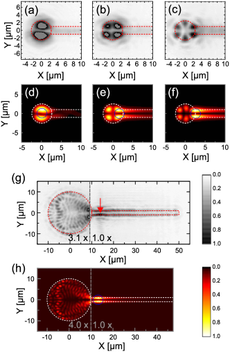
We begin our discussion with the smallest structure characterized by a trapping region of 5 µm in diameter. By varying the pump spot position close to the trap, we were able to select the orbital quantum number of the trapped quantized mode as shown in Figs. 2 (a)-2(c). The wave functions of these cylindrical modes are described by a radial () and orbital () quantum number where corresponds to the number of radial nodes and to the number of orbital nodes. The orbitals of the mode with their characteristic 2, 4, and 6 lobes pattern are excited by gradually imposing , 1.5, and 2.5m, respectively. These modes are enforced by the continuity of the wave function at the boundary with the guide which, as discussed above, favors the two lobe profile which in turn imprints its symmetry to the trap modes. The spot position determines the overlap of the exciton reservoir Bajoni2008 with the trap modes and selects the angular momentum [see appendix A] as confirmed by our simulations [see Figs.2](d)-2(f). Since the selection of a distinct mode comes together with an energy selection we can utilize this to control the polariton condensate flow into the wire.
When excited at the wire, polaritons flowing away from the laser spot act as a resonant injection into high-orbital modes of the trap. This excitation scheme allows for a separation of the background exciton reservoir formed by the pump spot and the emission at the trap by several micrometers. Therefore interactions of the condensate with an incoherent exciton background are reduced Schmutzler2014 and thermalization is mostly governed by the scattering rates between 0D states which are dependent on the trap size Paraiso2009 .
Now in the case of a 20-µm-wide trap [see Fig. 2(g)] the eigenstates of the trap are quasidegenerated and nearly free propagation is possible. When pumping over the wire, the local blueshift is converted to kinetic energy and particles are expelled in both directions Wertz2012 , a stationary scattering pattern, imposed by the wire mode, is visible in the trap. This mode resembles a double heartshape with an entry angle of about 69 degrees which is reproduced by solutions of Eq. (Exciton-Polariton Flows in Cross-Dimensional Junctions) [see Fig. 2(h)].
.
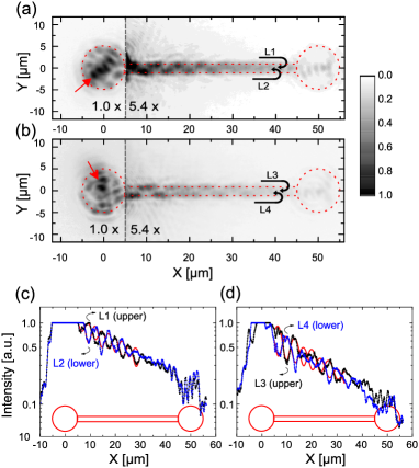
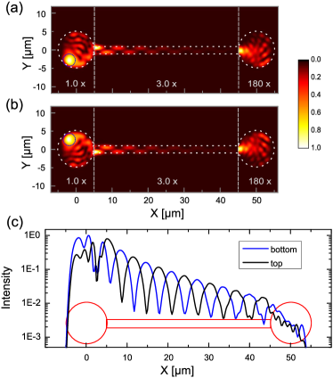
Our potential landscape furthermore allows us to select the nature of the guided modes by tuning the position of the pump spot on the trap. We excite the trap of the 10-µm-dumbbell at the very edge and a distinct angle to inject into a state of high orbital momentum and thus an energy close to the unbound states [see Figs. 3(a) and 3(b), laser position is marked by a red arrow]. Under such excitation, we excite a combination of both wire modes and therefore the condensate can propagate into the wire. As the n=1 and n=2 state of the wire are excited with different wave vectors, an interference-induced intensity oscillation is visible in the real-space image in the wire. The observed pattern is similar to the one obtained in the context of multimode interferences Soldano1995 . Two line profiles parallel to the wire [L1 and L2 in Fig. 3(a)] reveal a damped oscillation which is in antiphase for upper and lower part [see Fig. 3(c)]. Such a behavior is accurately reproduced by our simulations in Fig. 4(a).
The combination of propagating wave vectors can be changed by symmetrically injecting polaritons from the opposite direction in respect to [see Fig. 3(b), Fig. 4(b) for according simulations]. In this case the oscillation has its first maximum in the lower part of the wire (L4) which is revealed in the line profiles of L3 and L4 [see Fig. 3(d), Fig. 4(c) according theory]. We underline that by tuning the input intensity and therefore the local blueshift, one can select higher wave vectors and tune the periodicity of the wire emission pattern [see appendix B].
Conclusions.— We have demonstrated control over the spread of an exciton polariton nonequilibrium condensate in potentials which are imprinted into a GaAs-based semiconductor microcavity by an etch and overgrowth technique. These potentials are composed of areas with different in-plane dimensionality yielding different states. Utilizing real-space spectroscopy we directly map these states and investigate the resonant injection between the different parts of the potential. We have shown the possibility to use a wire connected to a cylindrical potential as a feed to resonantly inject a distinct mode in a robust manner. We believe that our results are crucial for the advanced design of polariton integrated circuits which interfaces optical elements of various dimensions.
Acknowledgements.— The Würzburg group acknowledges the financial support by the state of Bavaria and the ‘Deutsche Forschungsgemeinschaft’ (DFG) within the project Schn1376-3.1. S.K. acknowledges the European Commission for the H2020 Marie Skłodowska-Curie Actions (MSCA) fellowship (Topopolis). We would like to thank I. G. Savenko and M. Sun for discussions.
Appendix A Impact of pump shift and power
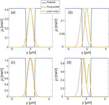
To shed light on the two lobe pattern obtained by pumping the wire, we resort to an effective 1D theory across the wire. We solve Eq. (Exciton-Polariton Flows in Cross-Dimensional Junctions) along the direction and assume full translational invariance in the direction. We show in Fig.A1 the condensate density pattern obtained for two different pump power and pump spot positions. As one can see below a threshold chemical potential, the condensation occurs in the mode of the wire demonstrating a one lobe pattern. The two lobe pattern emerges from the combination of a sufficient blueshift associated with a sufficient shift of the pump spot as one can see in panel (d) [see captions].
Appendix B Wire mode superposition
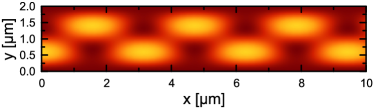
As shown in Fig. 3, the position of the pump spot in the trap allows exciting a combination of the and modes of the wire which is easily reproduced by considering two plane waves quantized along the -direction
| (2) | |||||
| (3) |
The resulting intensity pattern is shown in Fig.A2 in the case , , , , and m and reproduces the pattern observed in our experiment. The periodicity of the pattern is adjusted via .
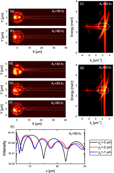
To be more quantitative, we have analyzed with our full 2D model the impact of the spot position in the 10m trap along the -direction on the interference pattern. The results are shown in Fig.A3 showing that the periodicity of the pattern can be tuned by varying and . While the interferences are suppressed for a fully centered spot in the low density [see panel (a)] and high density regime [see panel (b)] the situation changes as the spot is shifted in the -direction. From power dependent simulations shown in Figs. A3(d)-(f) for a spot shifted to it can be seen that oscillations are suppressed [see panel (d)] until the local blueshift reaches the energy of the wire mode [see panel (e)]. A second mode contribution is visible in the corresponding wire dispersion along [see panel (g)] in opposition to the centered spot [see panel (c)]. The pump power impacts as it allows targeting higher initial energy and therefore larger pairs of wave vectors, which manifests in a larger periodicity of the oscillation [see panels (e) and (f)]. The attack angles of the waves repelled by the high density pump spot allow us to tune the value and therefore the pattern [see panel (h)].
References
- (1) J. Kasprzak, M. Richard, S. Kundermann, A. Baas, P. Jeambrun, J. M. J. Keeling, F. M. Marchetti, M. H. Szymanńska, R. André, J. L. Staehli, V. Savona, P. B. Littlewood, B. Deveaud, and Le Si Dang, Nature, 443, 409 (2006).
- (2) P. G. Savvidis, J. J. Baumberg, R. M. Stevenson, M. S. Skolnick, D. M. Whittaker, and J. S. Roberts, Phys. Rev. Lett. 84, 1547 (2000).
- (3) B. Nelsen, G. Liu, M. Steger, D.W. Snoke, R. Balili, K. West, and L. Pfeiffer, Phys. Rev. X 3, 041015 (2013).
- (4) J. Fischer, I.G. Savenko, M.D. Fraser, S. Holzinger, S. Brodbeck, M. Kamp, I.A. Shelykh, C. Schneider, and S. Höfling, Phys. Rev. Lett. 113, 203902 (2014).
- (5) C. Schneider, K. Winkler, M. D. Fraser, M. Kamp, Y. Yamamoto, E. A. Ostrovskaya, and S. Höfling, Reports Prog. Phys. 80, 16503 (2017).
- (6) L. Ferrier, E. Wertz, R. Johne, D. D. Solnyshkov, P. Senellart, I. Sagnes, A. Lemaître, G. Malpuech, and J. Bloch, Phys. Rev. Lett. 106, 126401 (2011).
- (7) I. Carusotto and C. Ciuti, Rev. Mod. Phys. 85, 299 (2013).
- (8) D.A.B. Miller, Nat. Photonics 4, 3 (2010).
- (9) T.C.H. Liew, A. V. Kavokin, T. Ostatnický, M.A. Kaliteevski, I.A. Shelykh, and R.A. Abram, Phys. Rev. B 82, 033302 (2010).
- (10) H. Flayac and I.G. Savenko, Appl. Phys. Lett. 103, 201105 (2013).
- (11) F. Marsault, H.S. Nguyen, D. Tanese, A. Lemaître, E. Galopin, I. Sagnes, A. Amo, and J. Bloch, Appl. Phys. Lett. 107, 201115 (2015).
- (12) T. Gao, P.S. Eldridge, T.C.H. Liew, S.I. Tsintzos, G. Stavrinidis, G. Deligeorgis, Z. Hatzopoulos, and P.G. Savvidis, Phys. Rev. B 85, 235102 (2012).
- (13) D. Ballarini, M. De Giorgi, E. Cancellieri, R. Houdré, E. Giacobino, R. Cingolani, A. Bramati, G. Gigli, and D. Sanvitto, Nat. Commun. 4, 1778 (2013).
- (14) E. Wertz, A. Amo, D.D. Solnyshkov, L. Ferrier, T.C.H. Liew, D. Sanvitto, P. Senellart, I. Sagnes, A. Lemaître, A. V. Kavokin, G. Malpuech, and J. Bloch, Phys. Rev. Lett. 109, 216404 (2012).
- (15) D. Niemietz, J. Schmutzler, P. Lewandowski, K. Winkler, M. Aßmann, S. Schumacher, S. Brodbeck, M. Kamp, C. Schneider, S. Höfling, and M. Bayer, Phys. Rev. B 93, 235301 (2016).
- (16) C. Sturm, D. Tanese, H.S. Nguyen, H. Flayac, E. Galopin, A. Lemaître, I. Sagnes, D. Solnyshkov, A. Amo, G. Malpuech, and J. Bloch, Nat. Commun. 5, 3278 (2014).
- (17) V. K. Kalevich, M. M. Afanasiev, V. A. Lukoshkin, D. D. Solnyshkov, G. Malpuech, K. V. Kavokin, S. I. Tsintzos, Z. Hatzopoulos, P. G. Savvidis, and A. V. Kavokin, Phys. Rev. B 91, 045305 (2015).
- (18) G. Nardin, Y. Léger, B. Pietka, F. Morier-Genoud, and B. Deveaud-Plédran, Phys. Rev. B 82, 045304 (2010).
- (19) O. El Daïf, A. Baas, T. Guillet, J.-P. Brantut, R.I. Kaitouni, J.L. Staehli, F. Morier-Genoud, and B. Deveaud, Appl. Phys. Lett. 88, 061105 (2006).
- (20) K. Winkler, J. Fischer, A. Schade, M. Amthor, R. Dall, J. Geßler, M. Emmerling, E.A. Ostrovskaya, M. Kamp, C. Schneider, and S. Höfling, New J. Phys. 17, 023001 (2015).
- (21) D. L. Boiko, PIERS Online, 4, 831 (2008).
- (22) R. I. Kaitouni, O. El Daïf, A. Baas, M. Richard, T. Paraïso, P. Lugan, T. Guillet, F. Morier-Genoud, J. D. Ganière, J. L. Staehli, V. Savona, and B. Deveaud, Phys. Rev. B 74, 155311 (2006).
- (23) G. Tosi, G. Christmann, N.G. Berloff, P. Tsotsis, T. Gao, Z. Hatzopoulos, P.G. Savvidis, and J.J. Baumberg, Nature Communications 3, 1243 (2012)
- (24) D. Bajoni, P. Senellart, E. Wertz, I. Sagnes, A. Miard, A. Lemaître, and J. Bloch, Phys. Rev. Lett. 100, 047401 (2008).
- (25) J. Schmutzler, T. Kazimierczuk, Ö. Bayraktar, M. Aßmann, M. Bayer, S. Brodbeck, M. Kamp, C. Schneider, and S. Höfling, Phys. Rev. B 89, 115119 (2014).
- (26) T.K. Paraïso, D. Sarchi, G. Nardin, R. Cerna, Y. Leger, B. Pietka, M. Richard, O. El Daïf, F. Morier-Genoud, V. Savona, and B. Deveaud-Plédran, Phys. Rev. B 79, 045319 (2009).
- (27) L. B. Soldano and E. C. M. Pennings, J. Light. Technol. 13, 615 (1995).