Energy loss spectroscopy of Buckminster C60 with twisted electrons: Influence of orbital angular momentum transfer on plasmon generation
Abstract
Recent experimental progress in creating and controlling singular electron beams that carry orbital angular momentum allows for new types of local spectroscopies. We theoretically investigate the twisted-electron energy loss spectroscopy (EELS) from the C60 fullerene. Of particular interest are the strong multipolar collective excitations and their selective response to the orbital angular momentum of the impinging electron beam. Based on ab-initio calculations for the collective response we compute EELS signals with twisted electron beams and uncover the interplay between the plasmon polarity and the amount of angular momentum transfer.
I Introduction
Collective excitations in nanostructures are at the heart of of the
research field nanoplasmonics Maier and Atwater (2005). A
standard and widely utilized method to access the details of such
collective modes is the electron-energy loss spectroscopy (EELS)
Schattschneider (2012). With the advent of vortex,
or twisted beams
Verbeeck et al. (2010); Van Boxem et al. (2015); Guzzinati et al. (2016)
it is timely to explore the add-on features when performing EELS with
such beams. A particular aspect of vortex beams is that they carry a
definite and controllable amount of orbital angular momentum (OAM)
which is related to the topological charge of the vortex. Remarkably,
vortex beams were also realized in a transmission electron microscope
(TEM) allowing so for an atomic spatial resolution. Typical phenomena
associated with the OAM of the twisted beam are dichroism in magnetic
systems Lloyd et al. (2012), and new types of Landau
states Bliokh et al. (2012); Schattschneider et al. (2014a).
Using
a similar concept as for the generation of the vortex
beams Grillo et al. (2015), the angular momentum after
scattering from the probe can be determined. Exploiting this feature
one may employ vortex-based EELS to investigate the system response
not only at a particular the linear momentum transfer, but also for a
well-defined orbital angular momentum transfer (OAMT). One
consequence for instance is that multipolar excitations can be
accessed even at small (linear) momentum transfer, which is known as
the optical limit in conventional EELS.
A prominent molecular example, where the excitation energy varies significantly with the multipolarity, is the Buckminster fullerene C60 Verkhovtsev et al. (2012a, 2013); Li et al. (2013). In our previous studies Schüler et al. (2015) we have already developed an accurate model, based on first-principle calculations, which is very suitable for studying EELS. In this contribution, we employ a slightly improved version of the model with the main focus on elucidating how the control of the OAMT can be utilized to map out multipolar excitations. After introducing the general theoretical formulation, we consider both, the case of an isolated molecule and a two-dimensional film of molecules. We show that by fixing the OAMT the encoded phase information results in specific features in the spectra. This effect is most pronounced for spectroscopy on a single molecule, but it also prevails for crystallized C60. Although we focus on the Buckminster fullerene here, the methodology and the formula below are general and applicable to other systems.
The paper is organized as follows. In Sect. II we revisit the basic formulation of EELS in view of a more general projectile wave-functions, such as ”twisted” electrons. Our parameterization of the underlying plasmonic response of the system is also discussed. Based on this model, we first illustrate the control of the multipolarity in Sect. III by studying the vortex-based EELS from a single molecule. After that we turn to a crystallized surface. Atomic units are used unless stated otherwise.
II Theoretical formulation
Given the initial and the final asymptotic states of the electrons are known and denoted by respectively and , the Fermi’s golden rule allows for the calculation of the transfer rate as Joachain (1975)
| (1) |
where () are the ground (excited) states of the targets with corresponding energy (), is the energy of the incoming or outgoing electrons, respectively, and is the Coulomb interaction. In a typical EELS setup the energy of the impinging electrons is much larger than the typical target excitations which allows neglecting exchange effects and simplifying the transfer rate eq. (1) to
| (2) |
The operator (expressed in second quantization) stands for the effective potential acting on the target,
| (3) |
while is the Coulomb potential. The fluctuation-dissipation theorem Giuliani and Vignale (2005) provides a link of the expression eq. (2) to the density-density response function Onida et al. (2002) by
| (4) |
Here, denotes the energy loss. Alternatively one can combine the convolution with the Coulomb potential in eq. (3) with the response function by introducing the dynamically screened interaction with
| (5) |
yielding
| (6) |
We note that eq. (6) can also be derived from classical considerations García de Abajo (2010).
So far the wave function of the in- or outgoing electrons have not been specified. Depending on the actual experimental setup, a wide range of scenarios is possible. Here we focus on spectroscopy with beams carrying orbital angular momentum, called twisted electron beams. They can be described by Verbeeck et al. (2012)
| (7) |
where cylindrical coordinates have been used. For later convenience, we express the position vectors as , with , and stands for the unit vector in direction. Note that the radial profile (which is kept general at this point) can depend on a transverse momentum component. In the case of wide beams as compared to the typical system size, transverse momentum transfer does, however, not play an important role Schattschneider et al. (2013). We will hence omit this momentum dependence of the profiles . The normalization is fixed by the orthonormality condition
| (8) |
Provided such twisted electrons scatter from a target besides the momentum in longitudinal direction, angular momentum might be transferred. The consequences of this effect depend on how the outgoing electrons are detected. We now focus on two typical scenarios.
II.1 Conventional TEM
In the TEM setup electrons are collected in a wide-angle analyzer after being transmitted through the sample Egerton (2009); García de Abajo (2010). For this reason, the angular momentum of the outgoing electrons is not determined. Assuming the electron beam is prepared in a twisted state and is detected with transverse momentum , one finds for the momentum-resolved EELS signal
| (9) |
Here, we have approximated the longitudinal momentum transfer by , which is obtained by a first-order Taylor expansion in . The angular momentum of the twisted beam thus directly influences the EELS signal provided the angular distribution is recorded. Integrating over all possible detection directions on the other hand,
yields the total cross section García de Abajo (2010)
| (10) |
An important conclusion to be drawn from eq. (II.1) is that the influence of the angular momentum on the EELS spectra enters through the radial beam profile (that depends on ). This is the case if the signal is collected by integrating over all possible directions.
II.2 Detection of angular momentum
The situation changes if the angular momentum of the scattered electrons is detected explicitly. Experimentally, this can achieved by a holographic vortex filter that the scattered beam traverses, thus separating the different angular momentum components by the propagation direction Schachinger et al. (2016). In this case the OAMT becomes an important control parameter Lloyd et al. (2012). Note that this characterization is only possible if the respective axis of in- and outgoing beam both coincide. In general, this is an approximation which is adequate for targets smaller than the beam waist Schattschneider et al. (2013). Based in thus assumption can most conveniently compute the effective potentials by solving Poisson’s equation,
| (11) |
exploiting the cylindrical symmetry. The ansatz (where ) reduces eq. (11) to the radial Poisson equation
| (12) |
which is solved in terms of the its Green’s function . Here, and denote the modified Bessel functions of first and second kind, respectively. As usual, and . For the radial part of the potential one finds
| (13) |
For a target possessing almost perfect spherical symmetry such as the C60 molecule, the expansion of the density-density response function in terms of fluctuation densities reads
| (14) |
Therefore, eq. (4) attains the form
| (15) |
An important special case occurs if the beam axis points through the center of the C60 molecule, as the integration over the angle is simplified by
| (16) |
Here, stands for the associated Legendre polynomials normalized in accordance with the spherical harmonics. The selection rule limits the sum over by in eq. (15) and hence excludes certain multipolar modes.
II.3 Density-density response of the C60 molecule
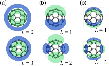
The central ingredient determining the (vortex) EELS signal is the density-density response function of the system, which comprises all types of excitations present in the system. This includes plasmons and particle-hole (–) excitations. Qualitative insights on the collective density fluctuations can be gained from semi-classical considerations Verkhovtsev et al. (2012b); Bolognesi et al. (2012), where the electronic density C60 molecule is approximated by a spherical shell. The density can thus only fluctuate at the inner and the outer surface, respectively, giving rise to symmetric or anti-symmetric oscillations and a volume plasmon. Our parameterization from ref. Schüler et al. (2015) provides an accurate fit to the fully-fledged first-principle calculations based o time-dependent density-functional theory (TDDFT) and yet allows for an intuitive classification of the plasmon modes as given in the semi-classical model. In particular, the density-density response function is expanded as in eq. (14), identifying the index with the radial quantum numbers. We distinguish between symmetric surface (SS) plasmons characterized by and multipolarity , anti-symmetric surface (AS) plasmons () and two types of volume plasmons (). The quenching of the volume plasmons (which is lacking in the semi-classical shell model) is a consequence of the delocalized nature of electron density. The plasmon modes entering our model are sketched (up to ) in Fig. 1.
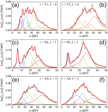
The model from ref. Schüler et al. (2015) is constructed from fitting functions for the spectra and the fluctuation densities , which allowed for an accurate modeling of the full density-density response function Schüler et al. (2016). Here, we use an improved version of the fitting procedure for the frequency dependence. Taking the spectral functions from our TDDFT calculations, we select the dominant peaks assuming a generic form
| (17) |
The weights , peak frequencies , and the broadening are then obtained from a least-square fit. The obtained spectra (up to ) are compared to the results of the ab initio calculations from ref. Schüler et al. (2015) in Fig. 2.
III Results
With the general theoretical formulation from Sect. II and an accurate model for the fluctuation densities and the corresponding spectra at hand, we can now analyze the inelastic scattering of the vortex beams from the C60 molecule. In line of a typical experimental realization Bliokh et al. (2012); Van Boxem et al. (2015); Schachinger et al. (2015), we choose Laguerre-Gauss modes as an approximation to the profile of the vortex beams:
| (18) |
Here, denote the associated Laguerre polynomials. We fix the radial node number to be . Note that is not an eigenstate of the free-particle Hamiltonian in this case. However, as the energy is carried in the longitudinal () direction, the energy of the beam is still sharply defined. Representing the vortex beams by the Laguerre-Gauss profile (18) shifts the dependence on the transverse momentum to the beam waist . We assume that is preserved upon scattering – an approximation that relies on the small size of the molecules on the scale of . By varying of the outgoing beam we confirmed that this assumption is justified to very good accuracy. This can be understood by the weak dependence of the effective potential on the beam profile, which is discussed now.
III.1 Effective potential
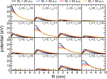
In fig. 3 we present the radial part of the effective potential as discussed in subsection II.2 for typical values of the beam waist . As we can infer from fig. 3, the effective potential quickly drops with increasing OAMT , which is explained by the decreasing overlap of the respective beam profiles. The potential displays a plateau behavior around for , while it vanishes at this point for . The asymptotic behavior is determined by , i. e. for small momentum transfer as typically encountered in high-energy EELS, the effective potential can be quite long-ranged affecting the molecules situated far away from the beam axis. This is very different from photons carrying orbital angular momentum. In a conventional EELS setup, the effective potential reads and thus exhibits a quadratic divergence for . The effective potential caused by scattering of twisted electrons on the other hand shows a logarithmic divergence, as expected for a two-dimensional regularization due to using beams with a finite width.
III.2 Loss spectra: beam focused on molecule
If the beam axis passes through the molecule’s center the selectivity with respect to the OAMT is most pronounced due to eq. (16). As the energy of impinging electrons is large ( keV), the longitudinal momentum transfer is in the range of a. u. approaching the optical limit for the C60 molecule. As previously discussed Schüler et al. (2015), the dominant excitations for small are the SS plasmons and the dipole SS plasmon in particular. Volume plasmons can however also be induced due to the radial dependence of the beam. Increasing the OAMT we expect the loss spectra are shifted to higher energies, as the frequencies of the SS plasmons grow with the multipolarity.
To confirm this dependence, we computed the loss spectra for different values of and fixed the angular momentum of the scattered electrons at . The OAMT to the system is thus .
For evaluating eq. (15) we use the radial fluctuation densities and plasmon spectra from ref. Schüler et al. (2015). After solving the radial Poisson equation (12) by eq. (13), the effective potential is projected on the spherical harmonics with respect to the molecule’s center. Finally, the remaining integration over the distant from the center is performed. The momentum transfer is replaced by .
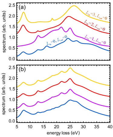
The resulting normalized spectra are presented in Fig. 4(a). For , only volume plasmons can be excited, leading to a broad loss spectrum which is consistent with the frequency dependence in Fig. 2(a). For , dipole plasmons can be induced (predominantly the SS plasmon). The loss spectrum is therefore similar to the optical absorption spectrum Reinköster et al. (2004). Increasing the OAMT, the plasmon dispersion with respect to the multipolarity leads to a shift of the spectra to higher energies. Furthermore, due to the changed beam profile, AS plasmons can also be induced, which further shifts the spectra. The dependence of the loss spectra on the angular momenta is quantified in table 1, where we give the overall peak positions (obtained by a Lorentzian fit) as a function of and .
The situation changes drastically if the requirement of detecting the outgoing angular momentum is dropped. As elaborated upon in subsection II.1, the effect of the OAMT should diminish. This is indeed consistent with our results for this case (Fig. 4(b)). The loss spectra exhibit a very weak dependence on the initial angular momentum of the beam which arises due to a changed beam profile only. Hence, not detecting the angular momentum leads to a loss of phase information which is directly reflected in the featureless spectra.
| 0 | 1 | 2 | 3 | 4 | ||
|---|---|---|---|---|---|---|
| 0 | 26.29 | 21.88 | 25.55 | 26.81 | 27.07 | |
| 1 | 21.88 | 24.97 | 21.87 | 25.53 | 26.74 | |
| 2 | 25.55 | 21.87 | 24.89 | 21.87 | 25.53 | |
| 3 | 26.81 | 25.53 | 21.87 | 24.85 | 21.87 | |
| 4 | 27.07 | 26.74 | 25.53 | 21.87 | 24.82 |
III.3 Loss spectra: crystalline phase
Conducting an EELS experiment on isolated C60 is very challenging, as preparing single molecules on the substrate used in the TEM setup is hardly possible. It is much more likely that the fullerenes crystallize on the surface of the substrate, forming a few layers of an FCC crystal (lattice constant nm at room temperature). To describe this setup theoretically, based on the previously employed model, we assume that the individual contributions of the molecules can be summed to obtain an adequate approximation to the response of the crystal:
| (19) | ||||
Here, denotes the lattice sites. This treatment ignores the hybridization of the plasmon modes into corresponding bands. The significance of such effects is not completely understood at the moment; first calculations Koval et al. (2015) report quite similar spectra as compared to the gas phase Bolognesi et al. (2012). As thin films are best suited for TEM experiments, we consider a single layer of molecules here. The geometry of the C60 is compared to the typical beam extensions in Fig. 5
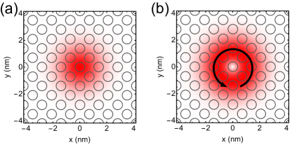
Note that the beam axis does not pass through most of the molecules’ centers, resulting in less sharply defined OAMT (which is defined with respect to the beam). The scenario of decentered beams questions the assumption of keeping the beam axis and waist constant throughout the scattering process. For the molecules located not to far from the vortex center, including the area of maximum intensity (which has the largest contribution to the total signal), the validity of this approximation has been underpinned in ref. Schattschneider et al. (2014b).
Analogously to the single-molecule case, we first analyze the scenario where the angular momentum of the outgoing electrons is explicitly detected. Evaluating the cross section (19) yields the loss spectra presented in Fig. 6. First we note that the difference between the spectra, when varying the OAMT, is not as pronounced as for the single molecules. This is a result of the collective response of many molecules located off-center with respect to the beam axis, as the OAM (which depends on the reference coordinate system) of the beam is blurred when considered from the fullerenes’ point of view. Hence, in spite the total OAMT is fixed, off-center molecules experience different many OAM components. Hence, the multipolar excitations can not be controlled as efficiently as before. Nevertheless, the phase information encoded in the OAM of the vortex beam leads to notable differences in the loss spectra. Generally, the trend is as in subsection III.2: the increased probability to induce multipolar excitations with growing OAMT shifts the spectra to higher frequencies. This behavior is mostly reflected in the less and less pronounced shoulder at eV (see the zoom in the lower panel in Fig. 6), which corresponds to the dominant feature of the SS dipole plasmon (see Fig. 2(c)). Hence, the contribution of the dipolar plasmons is suppressed. Interestingly, the peak eV is enhanced with increasing OAMT, as well. This peak corresponds to series of particle-hole excitations – in the bound-state manifold Usenko et al. (2016). The increasing weight of – excitations as compared to the plasmons is a signature of a more inhomogeneous driving acting on the system, as collective excitations only exist at small wave vectors (small angular momenta, respectively). This effect can also be observed in Fig. 4. In future works, we will map out the – excitations induced by vortex beams based on our ab initio approach from ref. Usenko et al. (2016).
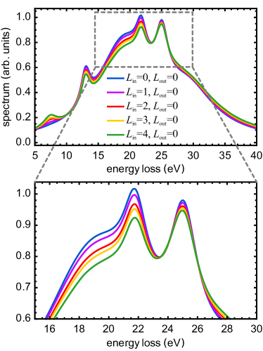
To demonstrate that the modification of the spectra in Fig. 6 depends on the phase of the vortex beam, we recomputed the loss spectra assuming that the OAM of the outgoing electrons is not detected (Fig. 7). Analogously to the discussion in subsection III.2, we find that the spectra for different ingoing OAM are basically identical, except for the case . The latter is due to a quite different beam profile (see Fig. 5(a)). Hence, it is truly the OAM of the vortex beams (which is pure phase effect) that can induce multipolar excitations and thus give rise to specific features in the loss spectra.
IV Conclusions
We presented the theoretical description of twisted electron energy loss spectra for both cases, when (i) the scattered electrons are detected in the full solid angle, and (ii) when the angular momentum of the scattered electrons is detected. While for (i) the angular momentum of the beam, encoded in the phase has no influence, we showed that it plays an important role in case (ii), particularly if the beam is aligned with the single molecule center. We applied the developed theory for EELS with twisted electrons for fixed molecules and for a single layer of crystallized fullerenes. The numerical findings are in line with the formal expectations: measuring the outgoing OAM of the beam allows controlling the OAMT and thus the multipolar excitations. This is directly reflected in the loss spectra. In contrast, detecting only the energy of the scattered electrons leads to almost identical spectra with varying OAM, since the phase information is lost and only the varying beam profile influences the overall spectra. So, we advocate the OAM-resolved vortex-based EELS as a powerful technique to access new information on the system’s excitations, particularly those of multipolar character.
Acknowledgments
We are indebted to Thomas Schachinger and Michael Stöger-Pollach for fruitful discussions and important insights from the experimental point of view, as well as to Yaroslav Pavlyukh for numerous discussions. The financial support by the grants of the German Research Foundation (DFG) SFB762 and the Priority Programme 1840 ”Quantum Dynamics in Tailored Laser Fields” (QUTIF) is gratefully acknowledged.
References
- Maier and Atwater (2005) S. A. Maier and H. A. Atwater, Journal of Applied Physics 98, 011101 (2005).
- Schattschneider (2012) P. Schattschneider, Fundamentals of Inelastic Electron Scattering (Springer Science & Business Media, 2012).
- Verbeeck et al. (2010) J. Verbeeck, H. Tian, and P. Schattschneider, Nature 467, 301 (2010).
- Van Boxem et al. (2015) R. Van Boxem, B. Partoens, and J. Verbeeck, Phys. Rev. A 91, 032703 (2015).
- Guzzinati et al. (2016) G. Guzzinati, A. Béché, H. Lourenço-Martins, J. Martin, M. Kociak, and J. Verbeeck, arXiv:1608.07449 [cond-mat, physics:physics, physics:quant-ph] (2016).
- Lloyd et al. (2012) S. Lloyd, M. Babiker, and J. Yuan, Phys. Rev. Lett. 108 (2012).
- Bliokh et al. (2012) K. Y. Bliokh, P. Schattschneider, J. Verbeeck, and F. Nori, Physical Review X 2, 041011 (2012).
- Schattschneider et al. (2014a) P. Schattschneider, T. Schachinger, M. Stöger-Pollach, S. Löffler, A. Steiger-Thirsfeld, K. Y. Bliokh, and F. Nori, Nature Communications 5 (2014a).
- Grillo et al. (2015) V. Grillo, G. C. Gazzadi, E. Mafakheri, S. Frabboni, E. Karimi, and R. W. Boyd, Phys. Rev. Lett. 114, 034801 (2015).
- Verkhovtsev et al. (2012a) A. V. Verkhovtsev, A. V. Korol, A. V. Solov’yov, P. Bolognesi, A. Ruocco, and L. Avaldi, J. Phys. B 45, 141002 (2012a).
- Verkhovtsev et al. (2013) A. V. Verkhovtsev, A. V. Korol, and A. V. Solov’yov, Phys. Rev. A 88, 043201 (2013).
- Li et al. (2013) C. Z. Li, Z. L. Mišković, F. O. Goodman, and Y. N. Wang, Journal of Applied Physics 113, 184301 (2013).
- Schüler et al. (2015) M. Schüler, J. Berakdar, and Y. Pavlyukh, Phys. Rev. A 92, 021403 (2015).
- Joachain (1975) C. J. Joachain, Quantum collision theory (North-Holland, 1975).
- Giuliani and Vignale (2005) G. Giuliani and G. Vignale, Quantum Theory of the Electron Liquid (Cambridge University Press, 2005).
- Onida et al. (2002) G. Onida, L. Reining, and A. Rubio, Rev. Mod. Phys. 74, 601 (2002).
- García de Abajo (2010) F. J. García de Abajo, Rev. Mod. Phys. 82, 209 (2010).
- Verbeeck et al. (2012) J. Verbeeck, H. Tian, and A. Béché, Ultramicroscopy 113, 83 (2012).
- Schattschneider et al. (2013) P. Schattschneider, S. Löffler, and J. Verbeeck, 110, 189501 (2013).
- Egerton (2009) R. F. Egerton, Rep. Prog. Phys. 72, 016502 (2009).
- Schachinger et al. (2016) T. Schachinger, A. Steiger-Thirsfeld, S. Löffler, M. Stöger-Pollach, D. Pohl, B. Rellinghaus, and P. Schattschneider, The 16th European Microscopy Congress (2016).
- Verkhovtsev et al. (2012b) A. Verkhovtsev, A. V. Korol, and A. V. Solov’yov, Eur. Phys. J. D 66, 253 (2012b).
- Bolognesi et al. (2012) P. Bolognesi, L. Avaldi, A. Ruocco, A. Verkhovtsev, A. V. Korol, and A. V. Solov’yov, Eur. Phys. J. D 66, 254 (2012).
- Schüler et al. (2016) M. Schüler, Y. Pavlyukh, P. Bolognesi, L. Avaldi, and J. Berakdar, Scientific Reports 6, 24396 (2016).
- Schachinger et al. (2015) T. Schachinger, S. Löffler, M. Stöger-Pollach, and P. Schattschneider, Ultramicroscopy 158, 17 (2015).
- Reinköster et al. (2004) A. Reinköster, S. Korica, G. Prümper, J. Viefhaus, K. Godehusen, O. Schwarzkopf, M. Mast, and U. Becker, J. Phys. B 37, 2135 (2004).
- Koval et al. (2015) P. Koval, M. P. Ljungberg, D. Foerster, and D. Sánchez-Portal, Nuclear Instruments and Methods in Physics Research Section B: Beam Interactions with Materials and Atoms 26th International Conference on Atomic Collisions in Solids, 354, 216 (2015).
- Schattschneider et al. (2014b) P. Schattschneider, S. Löffler, M. Stöger-Pollach, and J. Verbeeck, Ultramicroscopy 136, 81 (2014b).
- Usenko et al. (2016) S. Usenko, M. Schüler, A. Azima, M. Jakob, L. L. Lazzarino, Y. Pavlyukh, A. Przystawik, M. Drescher, T. Laarmann, and J. Berakdar, arXiv:1605.07858 [physics] (2016).