![[Uncaptioned image]](/html/1610.04380/assets/x1.png)
|
Bidirectional particle transport and size selective sorting of Brownian particles in a flashing spatially periodic energy landscape |
| Fernando Martinez-Pedrero,a Helena Massana-Cid,a Till Ziegler,b Tom H. Johansen,c,d Arthur V. Straube,a,e and Pietro Tierno∗a,f,g |
We demonstrate a size sensitive experimental scheme which
enables bidirectional transport
and fractionation of
paramagnetic colloids in a fluid medium.
It is shown that two types of magnetic colloidal particles
with different sizes
can be simultaneously transported in opposite directions,
when deposited above a stripe-patterned
ferrite garnet film subjected to
a square-wave magnetic modulation.
Due to their different sizes, the particles
are located at distinct elevations above the surface,
and they experience two different energy landscapes,
generated by the modulated magnetic substrate.
By combining theoretical arguments and numerical simulations,
we reveal such energy landscapes, which fully explain the bidirectional transport
mechanism.
The proposed
technique does not require pre-imposed channel geometries
such as in conventional microfluidics
or lab-on-a-chip systems,
and permits remote control over the particle motion, speed and
trajectory, by using relatively low
intense magnetic fields.
The nonequilibrium dynamics of particles driven above periodic potentials are common to different physical and biological systems, from vortices in superconductors, 1 to charge density waves, 2 frictional surfaces, 3 cell migration 4 and molecular motors. 5 On the technological side, periodic potentials generated by patterned substrates have been successfully used in the past to transport and separate microscopic particles dispersed in a fluid medium. It is possible to direct different particle species along separate paths under similar experimental conditions, when the interaction of the particles with the imposed landscape depends on their particular properties, such as their size, electric, magnetic susceptibility or surface charge. Particle sorting has been demonstrated in the past via electric 6, 7, 8, magnetic 9, 10, 11, 12 and optic 13, 14, 15 fields among other types of driving mechanisms. 16, 17 In most of the cases, the colloidal species are deflected from the periodic potential, and the degree of deflection is used to transport different particles towards different locations. A smaller number of experimental realizations have demonstrated the possibility to use an external field to direct the particles in opposite directions. In this context, most of the examples have been obtained by driving the particles with an electric field, in presence of a periodic pattern, 6, 18, 8 or using binary mixtures of oppositely charged particles. 19, 20 This task is even more challenging if the particles are driven with a magnetic field. In this case the periodic potential is usually generated by a structured magnetic substrate, and unless a proper strategy to steer polarizable particles is designed,10, 12 the magnetic particles typically exhibit a unidirectional transport.
In this article we report on the controlled transport and separation of paramagnetic colloidal particles driven by an externally modulated spatially periodic energy landscape, generated across the surface of a structured magnetic substrate.
We demonstrate via real-time experiments that colloidal particles of different sizes can be transported in opposite directions at a well defined speed, the latter being mainly controlled by the driving frequency of the applied field. The mechanism behind the bidirectional transport is rather robust, and it is fully determined by the different shapes that the magnetic potential adopts at the different particle elevations. We use theoretical arguments to assess the shape of these energy landscapes, finding a good agreement between the experimental data and the numerical simulations performed using these potentials. Extending our procedure to a polydisperse colloidal system, we determine the sensitivity to sorting colloidal species when transported across the magnetic substrate.
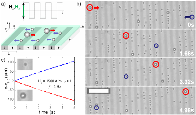
Fig. 1(a) shows a sketch of the experimental system. The substrate potential is generated by the stray field of a bismuth substituted ferrite garnet film (FGF), of composition Y2.5Bi0.5Fe5-qGaqO12 (). The FGF is grown by dipping liquid phase epithaxy, and is characterized by parallel ferromagnetic domains with alternating up and down magnetization and a spatial periodicity of . 21 Bridging the magnetic domains are Bloch walls (BWs), i.e. narrow transition regions where the magnetization vector rotates by degrees. The position of the BWs can be easily manipulated with the aid of a relatively low (few mT) external field, a feature which is used to modify the magnetic stray field of the film. We demonstrate the bidirectional transport by dispersing small (s) and large (L) paramagnetic colloids above the FGF, with diameters (Dynabeads Myone, Dynal) and (Dynabeads M-270, Dynal), and magnetic volume susceptibilities and , respectively. 22, 23 Both types of particles are composed of a crosslinked polystyrene matrix with surface COOH groups and are diluted in highly deionized water (MilliQ) before being deposited above the FGF surface.
Once above the FGF, the particles sediment due to density mismatch, and are attracted by the stray field of the film, which confines them to the horizontal plane. To avoid particle sticking and reduce the strong attraction of the FGF, we coat the latter with a uniform layer (thickness ) of a positive photoresist AZ-1512 (Microchem, Newton, MA) via standard spin coating and UV photo-crosslink. 24 Due to weak residual electrostatic repulsive interaction, particles hover slightly above the coating layer without mechanically touching it. Under no applied field, the FGF generates a one-dimensional -periodic magnetic landscape. The particles are attracted to the minima of the landscape located above the BWs and stay at fixed elevations, for the small or for the large particles. The external fields are applied with a custom-made triaxial coil system connected to a wave generator (TTi-TGA1244, TTi) feeding a power amplifier (IMG STA-800, Stage Line). The particle dynamics are visualized with an upright optical microscope (Eclipse Ni, Nikon) equipped with a CCD camera (Scout scA640-74f, Basler) operating at frames per second.
As shown in Fig. 1(a), we transport the magnetic colloids above the FGF film upon application of a square-wave magnetic field, , where is the signum function and denotes the driving frequency. The field strength can be described in terms of the amplitude and the field anisotropy . The applied field modulates the magnetic domains such that the potential is switched between two states every half () a period, , inducing a net particle current above the FGF. Before discussing in detail the resulting potential, we will describe the main experimental observations. As shown in Fig. 1(b), we find that for a certain range of field amplitudes and anisotropies, particles of different size are transported in opposite directions above the FGF surface. In particular, the series of polarization microscopy images in Fig. 1(b) show one large particle (highlighted by the red circle) and a small particle (highlighted by the blue circle), which completely exchange their positions after . Both particles display step-like trajectories reflecting the discontinuous nature of the driving field, see Fig. 1(c) and Supporting Information (VideoS1). The particle motion proceeds through a series of successive steps: every half a period , when the oscillating field changes sign, the particles start to move towards the nearest energy minimum (steep part of the trajectory) at a distance of one magnetic domain (), reach it and wait (flat part of the trajectory) for a next change of sign. This movement leads to an average speed with . In a more concentrated system, particles propelling in opposite directions might accidentally collide. In this case, the small particles usually slide over the surface of the large ones and continue further almost unperturbed. Thus, for the discontinuous magnetic modulation used here, the magnetic dipolar interactions between particles of different sizes are irrelevant, as recently observed for a binary mixture of particles driven unidirectionally by a continuous modulation.25 In contrast, the pair interactions between similar particles are non-negligible, as discussed in a previous work.26 However, for the measurements of average speed, we avoid chain formation by using low concentrations of particles, such that the pair interactions do not affect the particle motion. We also note that the bidirectional transport observed for the square-wave modulation was not found for other types of magnetic driving, such as linear oscillating 27 or rotating magnetic fields. 28
In order to understand the mechanism behind the bidirectional transport, we calculate the magnetic energy landscape generated by the FGF surface under the influence of an external field. We consider two paramagnetic colloidal particles having different diameters , volumes , and effective magnetic volume susceptibilities . Under a magnetic field the particles acquire a dipole moment , and an energy . Here, is the magnetic permeability of the free space, and the global magnetic field is the sum of the external modulation and the substrate field expressed as 29
| (1) |
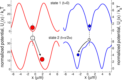
with and . Here, with the wave number, is the saturation magnetization, and is the displacement of BWs via the external field, where is a prefactor which determines the amplitude of such displacement. Fig. 2 shows the magnetic energy landscape for the two particles calculated at two different time steps, separated by half a period of the driving field. The modulation switches the potential between two states, which are represented by the -periodic profiles in the top (state 1) and bottom (state 2) panels of the image. Because of exponentially strong dependence on the elevation in eqn (1), small differences in the particle size significantly affect the shape of the potential seen by the two types of particles. As shown in Fig. 2, the potential for a small particle has a more complex shape as compared to the magnetic landscape of the large one. This shape results from higher order harmonic terms in the Fourier expansion of eqn (1) which decrease with the elevation, thus remaining non-negligible for the small particle but becoming less relevant for the large one. In both cases, a particle in state appears close to a maximum when the switching to state occurs and tends towards the nearest minimum. The crucial point is that the emerging maximum is always slightly displaced with respect to the minimum, to the left for the large and to the right for the small particles, forcing the two species to move in opposite directions.30 At low frequencies (such that a particle has enough time to reach its target minimum within the time ), its average speed , as discussed above. In contrast, when the switching between the two states is too fast, the particle is unable to reach the minimum in such brief period of time and gets trapped, moving back and forth between the two minima in states and . As a consequence, at high frequencies the average speed vanishes for both types of particles.
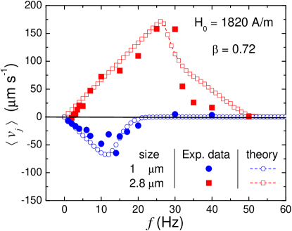
In order to probe these theoretical arguments, we next perform a series of experiments and measure the average speed of the two types of driven particles, varying the frequency and keeping constant the amplitude and the anisotropy of the applied field. The experimental data in Fig. 3 (the filled symbols) show the speeds having different signs for the two types of particles. In both cases, the motion is characterized by two well defined regimes, as described above. At low frequencies, the particles display net motion with the average speed that increases almost linearly with . In contrast, beyond a critical value ( for the small particles and for the large ones), the beads cannot follow the flashing minimum, showing a gradual decrease of with . To achieve a quantitative agreement with the experiment, we simulate the individual dynamics of particles in the magnetic potential based on eqn (1) with account of thermal fluctuations, as described by the equation
| (2) |
Here, is the viscous friction coefficient, is the dynamic viscosity of the solvent, is the thermal energy, and is a Gaussian white noise with zero mean and unit covariance. The results of the numerical simulations, shown as empty symbols in Fig. 3, agree well with the experimental data for all the range of frequencies explored. In the numerical simulation we fixed the elevation of the particles as () for the small (large) particle, considering that the thickness of the polymer film covering the FGF surface is . We used the corresponding experimental values for the field amplitude and the anisotropy . The saturation magnetization was a free parameter and we find the best agreement with .
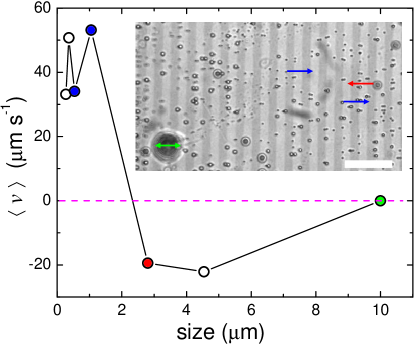
We now explore the sorting capability of our system by changing the size of the employed paramagnetic particles. We deposit on the FGF a polydisperse suspension composed of particles having different sizes, from to . The corresponding average speeds for a suspension subjected to a field with amplitude , frequency and anisotropy , are shown in Fig. 4. Particles having size display a positive velocity, while larger particles are transported in opposite direction. We note that the largest particle () is unable to move on average. For such long distance to the particle center, the landscape gets perfectly symmetric, and the potential switches between two inverted states, which forbids any net motion.31 Moreover, because of stronger thermal fluctuations, smaller nano-particles exhibit a lower speed as compared to the paramagnetic colloids having size. Fig. 4 makes it evident that the threshold for the magnetic separation depends crucially on the distance between the particle center and the FGF, assuming that each particle is doped by the same fraction of magnetic content. One thus can increase or reduce the thickness of the polymer film deposited above the FGF in order to tune this threshold, allowing to efficiently sort magnetic colloids with different sizes.
To summarize, we have experimentally demonstrated and theoretically explained a novel method to control and transport paramagnetic colloids in opposite directions. We note that an earlier study using a different FGF film showed an apparently similar size-based particle separation method.27 In that work, bidirectional motion of a bidisperse mixture of particles was induced by applying a rather complicated Lissajous-like magnetic modulation, characterized by two different driving frequencies. In contrast, here we straightforwardly use one driving frequency and a switching field which simultaneously generates different energy landscapes depending on the elevation. The transport method proves robust over a wide range of field parameters, allowing one to reach an unprecedented difference in the speed between particles of different sizes, as high as . As for fundamental implications of our work, the realization of a flashing potential able to simultaneously generate opposite particle fluxes may prompt further extensions of previously developed ratchet models 31, 32. In this context, an intriguing aspect would be the role of the thermal fluctuations in the process, which are negligible for the large particles used in the present study, but become increasingly important while reducing the size of the particles down to the nanoscale. On the technological side, our work could provide a method to fractionate magnetic micro-spheres in a channel-free microfluidic environment, since it does not require the presence of hard walls to confine the motion of micro-particles. Furthermore, paramagnetic particles can be easily functionalized in order to target and bind specific biological or chemical agents, which could be then transported on command by the applied field. This feature opens up the possibility for novel applications in micro- and nanofluidic systems.
We thank L. Schimansky-Geier and I. M. Sokolov for valuable discussions. F. M. P., H. M. C. and P. T. acknowledge support from the ERC Starting Grant “DynaMO” (Proj. No. 335040). P. T. acknowledges support from Mineco (No. FIS2013-41144-P) and AGAUR (Grant No. 2014SGR878). A. V. S. and P. T. acknowledge support from a bilateral German-Spanish program of DAAD (project no. 57049473) via the Bundesministerium für Bildung und Forschung (BMBF).
References
- Cohen and Jensen 1997 L. F. Cohen and H. J. Jensen, Rep. Prog. Phys., 1997, 60, 1581.
- Grüner 1988 G. Grüner, Rev. Mod. Phys., 1988, 60, 1129.
- Bohlein et al. 2012 T. Bohlein, J. Mikhael and C. Bechinger, Nat. Materials, 2012, 11, 126.
- Mahmud et al. 2009 G. Mahmud, C. J. Campbell, K. J. M. Bishop, Y. A. Komarova, O. Chaga, S. Soh, S. Huda, K. Kandere-Grzybowska and B. A. Grzybowski, Nat. Phys., 2009, 5, 606.
- Julicher et al. 1997 F. Julicher, A. Ajdari and J. Prost, Rev. Mod. Phys., 1997, 69, 1269.
- Regtmeier et al. 2007 J. Regtmeier, R. Eichhorn, T. T. Duong, P. Reimann, D. Anselmetti and A. Ros, Eur. Phys. J. E, 2007, 22, 335.
- Kim et al. 2008 U. Kim, J. Qian, S. A. Kenrick, P. S. Daugherty and H. T. Soh, Anal Chem., 2008, 80, 8656.
- Bogunovic et al. 2012 L. Bogunovic, R. Eichhorn, J. Regtmeier, D. Anselmetti and P. Reimann, Soft Matter, 2012, 8, 3900.
- B. B. Yellen and Friedman 2005 O. H. B. B. Yellen and G. Friedman, Proc. Natl. Acad. Sci. U.S.A., 2005, 102, 8860.
- Gunnarsson et al. 2005 K. Gunnarsson, P. E. Roy, S. Felton, J. Pihl, P. Svedlindh, S. Berner, H. Lidbaum and S. Oscarsson, Adv. Mater., 2005, 17, 1730.
- Robert et al. 2011 D. Robert, N. Pamme, H. Conjeaud, F. Gazeau, A. Iles and C. Wilhelm, Lab Chip., 2011, 11, 1902.
- Lim et al. 2014 B. Lim, V. Reddy, X. Hu, K. Kim, M. Jadhav, R. Abedini-Nassab, Y.-W. Noh, Y. T. Lim, B. B. Yellen and C. Kim, Nat. Comm., 2014, 5, year.
- Xiao and Grier 2010 K. Xiao and D. G. Grier, Phys. Rev. E, 2010, 82, 051407.
- MacDonald et al. 2013 M. P. MacDonald, G. C. Spalding and K. Dholaki, Nature, 2013, 426, 421.
- Brzobohatý et al. 2013 O. Brzobohatý, V. Karásek, M. Siler, L. Chvátal, T. Ci’már and P. Zemánek, Nat. Photon, 2013, 7, 123.
- g. Ma et al. 2015 X. g. Ma, P.-Y. Lai, B. J. Ackerson and P. Tong, Soft Matter, 2015, 11, 1182.
- Morton et al. 2008 K. J. Morton, K. Loutherback, D. W. Inglis, O. K. Tsui, J. C. Sturm, S. Y. Chou and R. H. Austin, Lab Chip., 2008, 105, 7434.
- Eichhorn et al. 2010 R. Eichhorn, J. Regtmeier, D. Anselmetti and P. Reimann, Soft Matter, 2010, 6, 1858.
- Vissers et al. 2011 T. Vissers, A. Wysocki, M. Rex, H. Löwen, P. Royall, A. Imhof and A. van Blaaderen, Soft Matter, 2011, 7, 2352.
- Vissers et al. 2011 T. Vissers, A. van Blaaderen and A. Imhof, Phys. Rev. Lett., 2011, 106, 228303.
- Tierno et al. 2009 P. Tierno, F. Sagués, T. H. Johansen and T. M. Fischer, Phys. Chem. Chem. Phys., 2009, 11, 9615.
- Clime et al. 2007 L. Clime, B. L. Drogoff and T. Veres, IEEE Trans. Magn., 2007, 43, 2929.
- Helseth 2007 L. E. Helseth, J. Phys. D: Appl. Phys., 2007, 40, 3030.
- Tierno 2012 P. Tierno, Soft Matter, 2012, 8, 11443.
- Tierno and Straube 2016 P. Tierno and A. V. Straube, Eur. Phys. J. E, 2016, 39, 54.
- Straube and Tierno 2014 A. V. Straube and P. Tierno, Soft Matter, 2014, 10, 3915.
- Tierno et al. 2008 P. Tierno, S. V. Reddy, M. G. Roper, T. H. Johansen and T. M. Fischer, J. Phys. Chem. B, 2008, 112, 3833.
- Tierno 2012 P. Tierno, Phys. Rev. Lett., 2012, 109, 198304.
- Straube and Tierno 2013 A. V. Straube and P. Tierno, Europhys. Lett., 2013, 103, 28001.
- Chauwin et al. 1994 J.-F. Chauwin, A. Ajdari and J. Prost, Eurohys. Lett., 1994, 27, 421.
- Reimann 2002 P. Reimann, Phys. Rep., 2002, 57, 361.
- Hänggi and Marchesoni 2009 P. Hänggi and F. Marchesoni, Rev. Mod. Phys., 2009, 81, 387.