Vortex scattering by impurities in a Bose-Einstein condensate
Abstract
Understanding quantum dynamics in a two-dimensional Bose-Einstein condensate (BEC) relies on understanding how vortices interact with each others microscopically and with local imperfections of the potential which confines the condensate. Within a system consisting of many vortices, the trajectory of a vortex-antivortex pair is often scattered by a third vortex, an effect previously characterised. However, the natural question remains as to how much of this effect is due to the velocity induced by this third vortex and how much is due to the density inhomogeneity which it introduces. In this work, we describe the various qualitative scenarios which occur when a vortex-antivortex pair interacts with a smooth density impurity whose profile is identical to that of a vortex but lacks the circulation around it.
I Introduction
In a recent paper Smirnov2015 , Smirnov & Smirnov have studied the scattering of two-dimensional (2D) vortex-antivortex pairs and solitons by a single quantum vortex in a homogeneous atomic Bose-Einstein condensate. They found that the pair is scattered over large angles radiating sound waves, in agreement with earlier calculations Parker2005 . This scattering process is important because it lies at the heart of the dynamics of 2D quantum turbulence, a problem which is currently attracting experimental and theoretical attention Nazarenko2007 ; Neely2013 ; Kwon2014 ; Stagg2015 ; Cidrim2016 ; Groszek2016 . Our understanding of the turbulent motion of many interacting vortices is based on recognizing the most elementary interactions, such as the interaction of a vortex with another vortex of the same or opposite sign (resulting respectively in rotational or translation motion of the pair). Similarly, we would like to recognize the possible elementary interactions between a vortex and a large density perturbation induced by the dynamics of vortices by external means. It is well-known that a quantum vortex in a Bose-Einstein condensate is a hole of zero density around which the phase changes by . The natural question is whether the incoming vortex-antivortex pair would be scattered (and if so, by which amount) by a density perturbation alone (without the circulation around it), as density gradients induce a Magnus force McGeeHolland2001 ; FetterSvidzinsky2001 which deflects the pair. To answer this question, we have performed numerical simulations of vortex-antivortex pairs travelling towards a fixed target in the form of a density perturbation (hereafter referred to as an ‘impurity’) and whose depth and size is similar to the depth and size of a quantum vortex (but without the circulation). Here we report about the significant scattering induced by the impurity, and compare it with the scattering induced by a target in the form of a vortex.
For simplicity we consider a homogeneous condensate at zero temperature, and aim at identifying the various qualitative scenarios which are possible (quantitative predictions of vortex trajectories in a harmonically trapped condensate require more specific calculations which depend on the actual physical parameters and geometry, and are outside the scope of this work). A better physical understanding of the scattering which imperfections induce on vortices is generally useful (although in general imperfections may not be as symmetric as we describe them here). Our results are also relevant to the manipulation of vortices using optical potentials generated by laser beams Davis2009 ; Aioi2011 .
II Model
Our model is the 2D Gross-Pitaevskii equation (GPE) for a homogeneous condensate at zero temperature. We use dimensionless variables based on the healing length , the time scale and the number density , where is the chemical potential, is the (2D) interaction parameter, and is Planck’s constant; the external potential is scaled by . The resulting dimensionless GPE
| (1) |
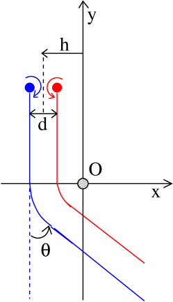
is solved in the (dimensionless) 2D domain . The initial condition at , schematically described in Fig. 1, is a vortex-antivortex pair, consisting of a left (clockwise) vortex and a right (anticlockwise) vortex initially placed respectively at positions , and , . We call . the initial distance between the vortices of the pair. The vortex-antivortex pair travels along the negative direction with impact parameter towards a fixed density perturbation (or impurity) held at . The impurity is represented by the (dimensionless) external potential where . With a suitable choice of parameters parameters , solving the time-independent GPE without the vortex-antivortex pair, the density profile of the impurity approximately matches the profile of a singly-charged vortex at , in the homogeneous condensate.
To quantify the scattering, we measure the deflection angle of the antivortex away from its initial trajectory, but in some cases (for example if the vortex-antivortex pair breaks up) a different description of the interaction is necessary.
We choose and impose on the boundaries. We use a grid, corresponding to the (dimensionless) spatial discretization . Time-stepping is performed using the 4th-order Runge-Kutta scheme; the typical (dimensionless) time step is . During typical evolutions the total energy is conserved within . The calculations were repeated in a box with discretization , resulting in the same qualitative scattering scenarios which we describe in the next section. Variations in the deflection angles resulting from discretization errors and from sound waves reflected from the boundaries are small (of the order of one percent); the trapping scenario appears more sensitive to perturbations. On the other hand, in the experiments, 2D vortex configurations typically contain significant sound waves besides thermal noise.
III Scattering scenarios
In all calculations we choose initial y-coordinates , sufficiently away from the impurity; the initial x-coordinates, and , vary from case to case, as we change the impact parameter and the vortex separation . We have identified three typical scenarios:
-
1.
Fly-by scenario
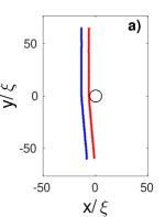
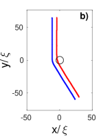
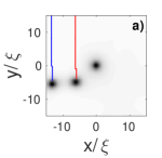
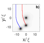
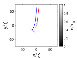
If the impact parameter is large and negative, the vortex-antivortex pair is too far at the left of the impurity, see Fig. 2(a), to be affected, and the deflection angle is . If the magnitude of decreases (still keeping ), the vortex-antivortex pair is scattered to the left (as seen from the initial direction of travel) with increasing positive deflection angle , as shown in Fig. 2(a,b).
-
2.
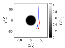
Trapping scenario
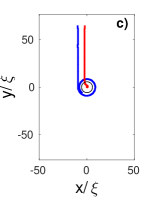
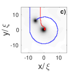
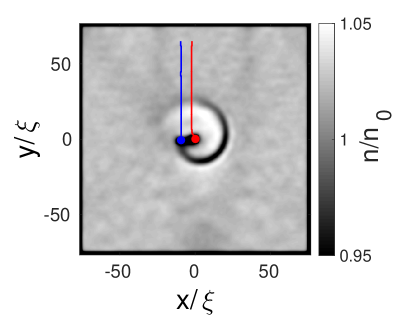
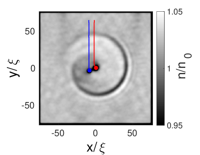
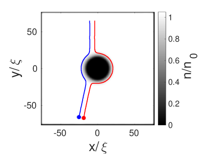
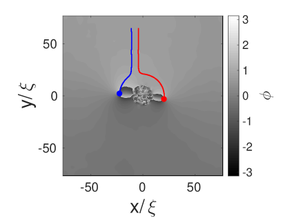
If the magnitude of is further decreased (still keeping ), the vortex falls into the region of low density of the impurity, see the red trajectory of Fig. 2(c), becomes trapped and stops, with a strong emission of sound waves, see Fig. 3; at this point, the isolated antivortex processes around the impurity, see the blue trajectory of Fig. 2(c). In this scenario the deflection angle cannot be defined.
-
3.
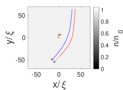
Go-around scenario
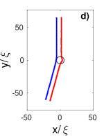
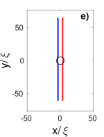
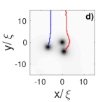
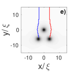
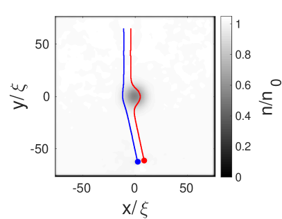
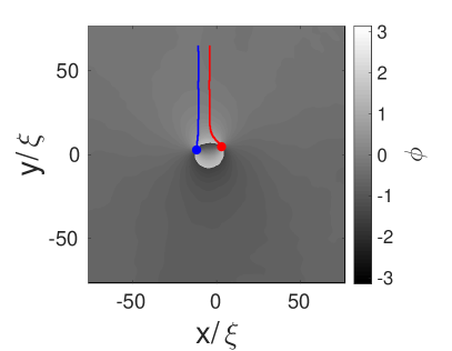
A further decrease of the magnitude of means that the vortex-antivortex pair is almost aimed at the impurity; the left (anticlockwise) vortex and the right (clockwise) vortex overtake the impurity on opposite sides, going around it along opposite directions, before joining again, re-forming the pair, and moving on to infinity. Fig. 2(d) shows that for slightly negative values of the vortex pair is scattered to the right (); for , see Fig. 2(e), the vortex-antivortex pair proceeds almost straight (), vortex and antivortex going around the impurity in opposite directions.
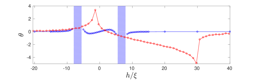
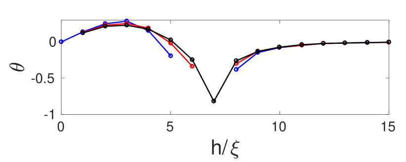
Finally, for larger, positive values of , the trajectories of the vortex and the antivortex are the same (as the impurity does not introduce any preferred orientation), being replaced by (in other words the function is antisymmetric in ). We summarize the scenarios which we have revealed by plotting the deflection angle as a function of the impact parameter , see the blue line and dots in Fig. 4(top). The shaded areas represent the regions where the deflection angle cannot be defined (one vortex becomes trapped) and the blue line is interrupted.
It is instructive to replace the impurity with a third vortex, choosing positive anticlockwise circulation, initially placed at . In this way we can directly compare the deflections of the vortex pair’s trajectory caused by a third vortex to the deflection caused by an impurity with the same density perturbation, isolating the effect of the vortex circulation. Unlike the impurity, which is fixed, the third vortex is free to move under the velocity field of the vortex-antivortex pair. The deflection angle caused by the third vortex is shown by the red line and dots of Fig. 4(top). It is apparent that, for large negative impact parameters, the deflection angle is approximately the same for vortex and impurity, but becomes significantly larger for the vortex at small negative ; moreover, there is no trapping regime for the vortex. Note also that, for the vortex, the curve is not antisymmetric about as in the case of the impurity: for , the closest interaction is between vortices of the same sign, which makes the two close vortices to rotate around each other causing a deflection to the left () with respect to the initial direction of motion; for , the closest interaction is between vortices of the opposite sign, which makes the two close vortices to travel away together, causing a deflection to the right (); with respect to the initial direction of motion. This is why the two peaks of the red curve of Fig. 4(top), which represent these strong interactions, are not symmetric about . Between these two peaks there is a regime in which the anti-vortex of the pair swaps place with the (initially stationary) third vortex, which couples with the original vortex of the pair and travels away with it, forming a new pair. An example of this swapping regime is presented in Fig. 5a. Finally, notice that the effect of the third vortex extends to large positive values of , unlike the effect of the impurity.
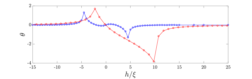
Fig. 4(bottom) shows what happens if we halve the initial separation of the vortex from the antivortex to . At this short separation, the trapping regimes disappears (the vortex, now rather close to the antivortex, moves at large speed, and the impurity is not strong enough to stop it). The other features of the interaction remain qualitatively the same as for the larger pair separation .
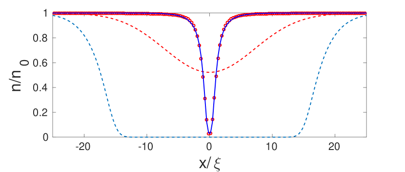
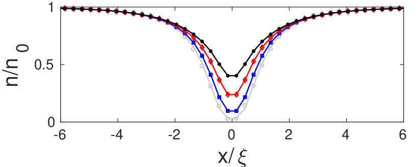
Increasing the size of the impurity or making it shallower - as for the density profiles shown by the dashed red and blue lines of Fig. 6 - does not change the scenarios of interaction with the vortex-antivortex pair in a qualitative way. Fig. 7(top left) and Fig. 7(bottom left) show the go-around scenario respectively for a large deep impurity and for a smaller, shallower impurity (the density at the centre is only ). It is interesting to notice that phase defects (ghost vortices) appear inside the large impurity - compare the top right and bottom right panels of Figs. 7. An example of the scattering regime with an impurity similar to the size of the large impurity of Fig. 6 (dashed blue line) is shown in 5b.
Changing the depth of the impurity whilst keeping the width close to that of a vortex only modifies the deflection angle slightly. For deeper impurities we generally see larger scattering angles in the region close to the impurity. The general trend is that the shallower the impurity is, the smaller the region in which trapping takes place (see Fig. 8), until the impurity is too shallow to trap a vortex, as shown by the black line of 8.
We have already pointed out (Fig. 3) that sound waves created by accelerating vortices Parker2005 . In general, these waves represent small acoustic losses of kinetic energy which we quantify by recalling the classical expression for the energy of a vortex ring of radius and core radius in a fluid of density , which is Barenghi2009 where . Neglecting variations of the slow logarithmic term, by measuring the change of distance between the vortex and the antivortex of the pair, we can estimate the relative energy loss , which is as high as for the scattering shown in Fig. 5(b).
IV Discussion and conclusions
We have compared trajectories of vortex-antivortex pairs launched either towards a third vortex or toward an impurity in the form of a similar density hole but without the circulation. By varying the impact parameter, we have identified three general scenarios (fly-by, trapping, go-around) which can occur. In the first scenario, the effect of the impurity if qualitative similar to that of the vortex, in the second and third scenarios it is significantly different. These scenarios represent the elementary processes which can be recognized within a turbulent system. They are therefore relevant to experiments in which vortices are manipulated by laser beams and to studies of 2D quantum turbulence, as large density perturbations are often generated by vortex annihilations or by the moving laser beam used to nucleate vortices in the first place.
Our results are consistent with work on the scattering of 2D quasi-solitons from potential barriers MironovSmirnov2012 , for example we observe that a vortex pair is deflected towards a density dip rather than away from it as predicted (see their Fig. 1, bottom). Our work is motivated by the aim of getting insight into what is typically seen in experiments and numerical simulations of 2D vortex turbulence, and differs from Ref. MironovSmirnov2012 in three respects. Firstly it is concerned with well-separated vortex and antivortex rather than solitons (when the speed of the pair exceeds the critical value where is the sound speed, the circulation is lost and the pair becomes a solitonic object). Secondly it refers to much smaller impurities (of the order of the core size, not ten times larger). In particular, unlike Ref. MironovSmirnov2012 , in our work the vortex and the antivortex which make up a pair can separate. Thirdly, by solving directly the GPE, we allow acoustic losses unlike the model equations of Ref. MironovSmirnov2012 .
Future work should look at the effects induced by an inhomogeneous density background in harmonically trapped condensates. Other aspects which are worth investigating are thermal and quantum fluctuations, which are not included in our mean field GPE model. Qualitatively, one would expect thermal fluctuations to move the vortex and the antivortex of a pair closer to each other, eventually leading to their annihilation. This effect would lead to the introduction of a new length/time scale associated with the vortex-antivortex pair’s intrinsic decaying dynamics. Qualitatively, however, we would still expect the same regimes to emerge. Quantum fluctuations would lead to an intrinsic jitter motion of each vortex about its mean position, with the target impurity also suffering some fluctuations from the fluctuating density in that region. On the average we would still expect the fly-be and go-around scenarios to persist, but our discussion here may represent a rather idealised case. In fact it would be interesting to investigate this scenario experimentally.
Acknowledgements.
We acknowledge the support of EPSRC grants EP/K03250X/1 and EP/I019413/1.References
- (1) L.A. Smirnov and A.I. Smirnov, Phys. Rev.A 92, 013636 (2015).
- (2) C.F. Barenghi, N.G. Parker, N.P. Proukakis and C.S. Adams, J. Low Temp. Phys. 138, 629 (2005).
- (3) S. Nazarenko and M. Onorato, J. Low Temp. Phys. 146, 31 (2007).
- (4) T.W. Neely, A.S. Bradley, E.C. Samson, S.J. Rooney, E.M. Wright, K.J.H. Law, R. Carretero-Gonzáles, P.G. Kevrekidis, M.J. Davis, and B.P. Anderson, Phys. Rev. Lett. 111, 235301 (2013).
- (5) W. J. Kwon, G. Moon, J.Y. Choi, S.W. Seo, and Y.I. Shin, Phys. Rev. A 90, 063627 (2014)
- (6) G.W. Stagg, A.J. Allen, N.G. Parker, and C.F. Barenghi, Phys. Rev. A 91, 013612 (2015).
- (7) A. Cidrim, F. E. A. dos Santos, L. Galantucci, V. S. Bagnato, and C. F. Barenghi, Phys. Rev. A 93, 033651 (2016).
- (8) A.J. Groszek, T.P. Simula, D.M. Paganin, and K. Helmerson, Phys. Rev. A 93, 043614 (2016).
- (9) S.A. McGee and M.J. Holland. Phys. Rev. A 63, 043608 (2001).
- (10) A.L. Fetter and A.A. Svidzinsky, J. Phys. Cond. Mat. 13 R135 (2001).
- (11) M.C. Davis, R. Carretero-Gonzalez, Z. Shi, K.J.H. Law, P.G. Kevrekidis, and B.P. Anderson, Phys. Rev. A 80, 023604 (2009).
- (12) T. Aioi, T. Kadokura, T. Kishimoto and H. Saito, Phys. Rev. X 1, 021003 (2011).
- (13) , , , , , , , .
- (14) V.A. Mironov and L.A. Smirnov, Phys. Wave Phenomena 21, 62 (2012).
- (15) C.F. Barenghi and R.J. Donnelly, Fluid Dyn. Res. 41, 051401 (2009).