Construction and Assembly of the Wire Planes for the MicroBooNE Time Projection Chamber
Abstract
In this paper we describe how the readout planes for the MicroBooNE Time Projection Chamber were constructed, assembled and installed. We present the individual wire preparation using semi-automatic winding machines and the assembly of wire carrier boards. The details of the wire installation on the detector frame and the tensioning of the wires are given. A strict quality assurance plan ensured the integrity of the readout planes. The different tests performed at all stages of construction and installation provided crucial information to achieve the successful realization of the MicroBooNE wire planes.
1 Introduction
MicroBooNE is a 170t Liquid Argon Time Projection Chamber (LArTPC) that is deployed in the Booster Neutrino Beam (BNB) at Fermilab [1]. High purity liquid argon serves as the neutrino target and tracking medium for the particles produced in neutrino interactions [2]. The TPC active volume is 87 tons of LAr and the readout plane is constructed out of wires, reading out ionization electron signals.
MicroBooNE detects neutrino interactions via the outgoing charged particles (and neutral particles that have converted to charged) from the neutrino-nucleon interaction which ionize the liquid argon. Ionization electrons produced by the passage of these charged particles are made to drift at constant velocity by application of a uniform electric field. This ionization charge drifts to three wire planes situated on the beam-right side of the detector. Electrostatic potentials of the three wire planes are set up to allow the ionization electrons to pass by the first two wire planes, leaving only induced charge signals, to reach the third wire plane, where they are collected on the wires. Figure 1 shows the operation principle of the MicroBooNE TPC.
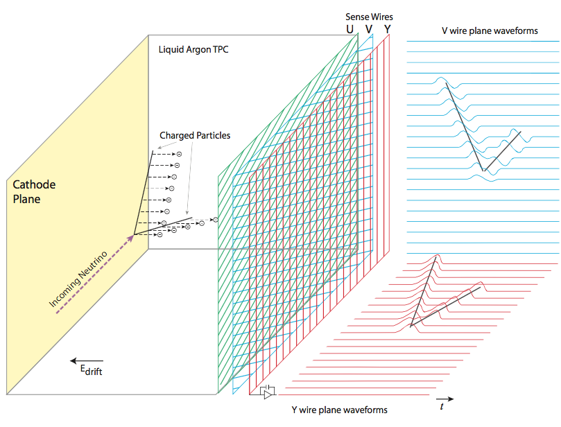 |
The successful operation of the LArTPC, and subsequent analysis of the collected data, relies on a precise knowledge of the location and orientation of all wires in the detector. Reconstruction of the charged particle trajectory is derived from the known wire positions and the arrival times of ionization electron signals on the wires, combined with the time that the interaction took place in the detector within the 1.6 s Booster Neutrino Beam (BNB) spill. The 3 mm wire pitch, combined to the sub-millimeter resolution in the drift direction due to the MicroBooNE nominal maximum drift velocity of 1600 ms and the 2 MHz sampling rate, enables 3d-position resolutions of the order of a cubic-millimeter. The full description of the MicroBooNE detector and subsystems can be found here [3].
2 Description of the MicroBooNE wire planes
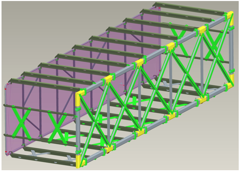
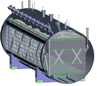
The MicroBooNE TPC design is shown in figure 2. The TPC, with dimensions of 2.56 m (drift length from cathode to anode) 2.33 m (height of the readout plane) 10.36 m (length of the readout plane), is inserted in a cylindrical cryostat. The active volume is defined as the volume that is readout by the wire planes, hence inside the TPC frame.
 |
 |
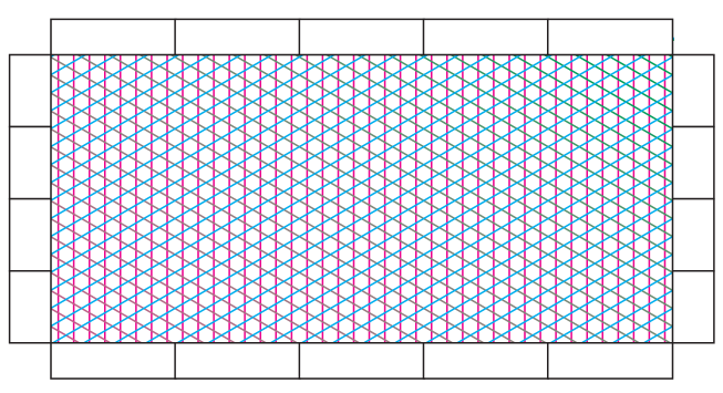
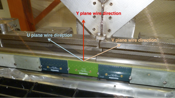
The design of the MicroBooNE wire planes is based partly on the ICARUS detector [4]. The TPC is composed of three wire planes Y, U and V, oriented vertically and at 60∘ from the vertical, respectively, as illustrated in figure 3. The planes are 2.33 m 10.36 m, the plane-to-plane separation is 3 mm, and the wire-to-wire separation is also 3 mm. The vertical Y-plane, which serves as the collection plane, is comprised of 3456 individual wires mounted in groups of 32 on wire carrier boards, for a total of 108 pairs of wire carrier boards installed for the Y plane. The wire carrier boards are described in greater detail in section 2.1. The two angled planes, U and V, serve as the two induction planes and are each comprised of 2400 wires, mounted in groups of 16 on 150 pairs of carrier boards.
 |
The wires are made of m diameter Type-304V stainless steel, the same material as the TPC frame to ensure identical thermal contraction. The wires are plated with 2 m of copper (to decrease the resistivity of the wire from 40 m to 3 m in order to reduce series noise in the readout electronics [5]) and covered with a thin flash (0.1 m) of gold to prevent the copper oxidation.
The original technical requirements for the wire plane design are fully detailed here [1]. Three wire planes were required to ensure redundancy to allow reconstruction of tracks parallel to one wire plane. The wire pitch and the wire plane separation were chosen to be 3 mm, the minimum spacing possible given the electronics signal-to-noise ratio and LAr purity requirements. The wire tension was originally designed to be 9.8 N to limit the sag due to gravity to be less than 0.5 mm on the longest 4.66 m wires. The tolerance on the length was 0.02%. However, it is important to mention that due to the R&D goals of MicroBooNE, some original requirements were modified during the final design and construction processes due to physical constraints or because it was demonstrated by simulations that the physics goals could still be achieved. For example, the final requirement on the tension in the TPC is 6.86 N. However, the tensioning device design did not allow to tension all the individual wire tensions within a factor two of that desired value. More discussion on these requirement changes can be found in section 1.
2.1 The wire carrier boards
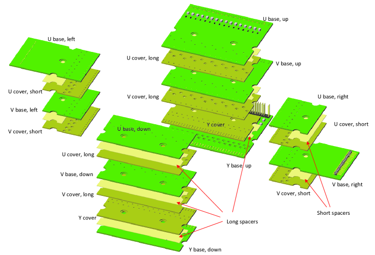
The wire carrier boards, shown schematically in figure 4, are made of FR4, comprised of three parts: a base, a cover, and a spacer, which are made using standard printed circuit board fabrication techniques. Rows of counter-bored pockets are machined into the base and cover. Once assembled, they form pockets that securely capture the brass wire-termination rings, described in section 3. The spacer maintains a small gap between the leading edge of the base and cover so the wires can move slightly around the terminating brass rings. Electrical contact to each wire is made by gold plated brass pins pressed in at the leading edge of the base board. These pins also define the location of the wires as they exit the wire carrier modules. The wires are hence attached to two boards: one to connect the wires to the detector readout system (top boards for the Y plane, left and top boards for the U plane and right and top boards for the V plane) and one, non-instrumented, to terminate and secure the wires on the frame (bottom boards for the Y plane, right and bottom boards for the U plane and left and bottom boards for the V plane) as shown in figure 4.
|
3 Wire winding and carrier board assembly
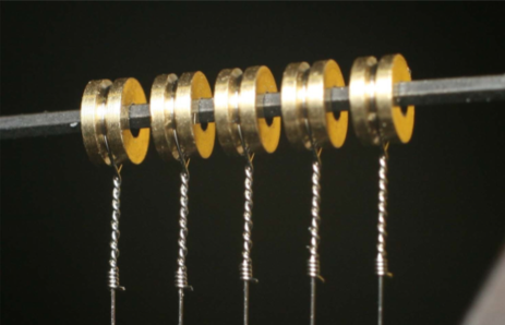
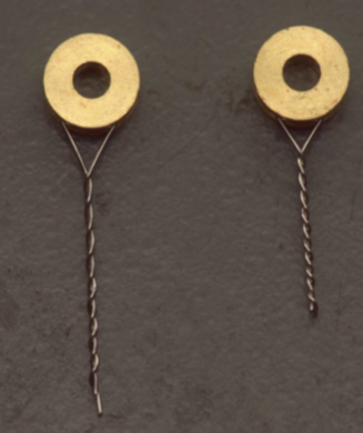
In order to construct the MicroBooNE wire planes, each TPC wire is prepared (cut to length and twisted around a brass ring as shown on the left in figure 5 and attached individually on a wire carrier board (center of figure 5). Once the wire carrier board is fully populated, a board spacer is inserted and the board is closed by a cover, and secured with two rivets (partial view shown in right panel of figure 5, shown without rivets). The preparation of each individual wire is facilitated by the use of automated wire winding machines designed for this purpose. In this section, we describe the wire winding machines and the winding procedures.
|
 |
|---|---|
|
3.1 Wire winding machines
The winding of MicroBooNE’s wires is performed via a semi-automated procedure using wire winding machines designed to measure and cut the desired wire lengths and to consistently wind the wires on the wire termination brass ring. Two machines were designed and built. One is used for fixed-length wires (for the vertical Y plane) and the other for variable-length wires (for the angled U and V planes).
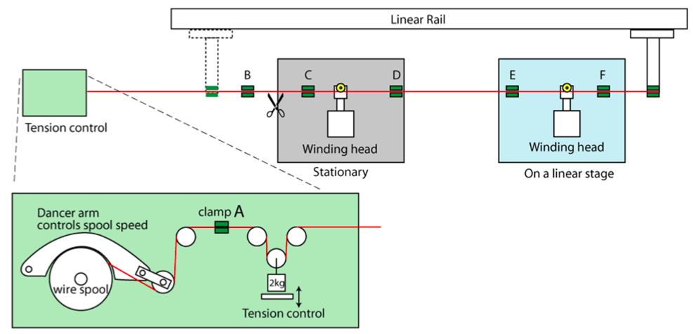
Figure 6 shows a schematic view of a wire winding machine. The first component of the machine is the distribution and tension station. A spool of wire is attached to the machine frame and the wire is unrolled with a robotic arm and pulley system. A weight of 1.4 kg is suspended from a mobile pulley in order to apply the nominal 0.7 kg or 6.86 N tension on the wire. This procedure ensures that the wires are cut to the correct length under tension at room temperature. The nominal tension of 6.86 N was chosen to be small enough to prevent wire breakage during cooldown, and large enough to limit the maximum wire sag due to gravity to be less than 0.5 mm.
|
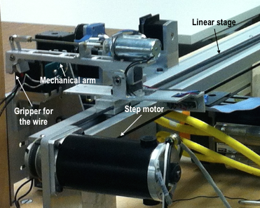
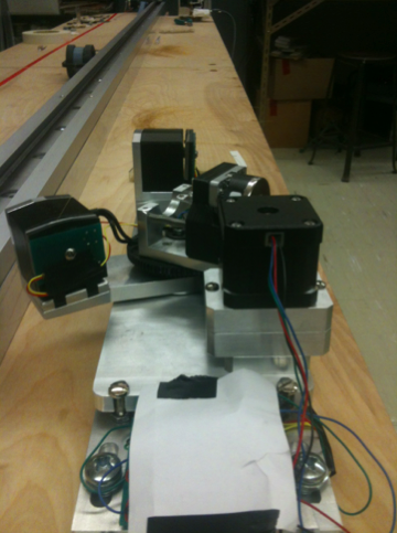
The second part of the machine is composed of a robotic arm mounted on a linear translation stage, as shown in figure 7. The arm is used to pick up the wire from the distribution station and pull it to the desired length. The linear stage provides excellent control on the length (better than 50 m precision) and is operated by computer controlled step motor. The Y plane has a fixed length of 2.5 m for all wires, but the U and V planes have variable wire lengths from 3.7 cm (in the corners) up to 4.66 m due to their 60∘ orientation and position along the frame.
|
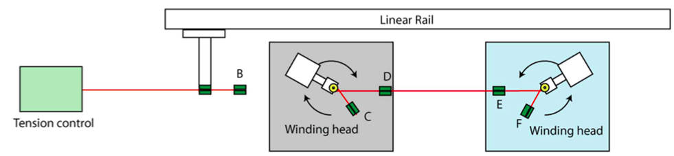
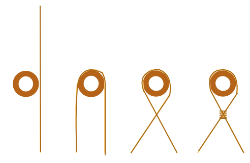
Finally, the third part of the machine consists of two winding stations (see figure 8) designed to attach each end of the wires to a small brass ring. The brass rings are 3 mm in diameter and 1.5 mm thick. The robotic arm deposits the wire just behind the brass rings (pre-installed manually on the winding heads) where it is clamped in place by electrically actuated grippers, and cutters automatically cut the wire. Once the wire is released by the arm, the winding heads rotate by 120∘ and start spinning in the plane perpendicular to the initial rotation, winding the wire around the ring six times. A twisted wire on the ring is shown on the top left in figure 5. Once the winding is performed, the machine’s work, the automated part of the procedure, is complete. It goes to rest and operators take over to complete the procedures described in the next section.
 |
 |
 |
3.2 Procedures for the assembly of the wire carrier boards
After the automated stage, the wire (of the correct length) is left twisted around the brass rings. The final step of the wire preparation requires an operator to manually cut the the excess wire remaining at the end of the twisted wire (cutting away the wire section from the brass ring to block C, as well as the section from the other brass ring to block F, both shown in figure 8), ensuring that the cut is very close to the twist to avoid sharp edges and short-circuits in the boards.
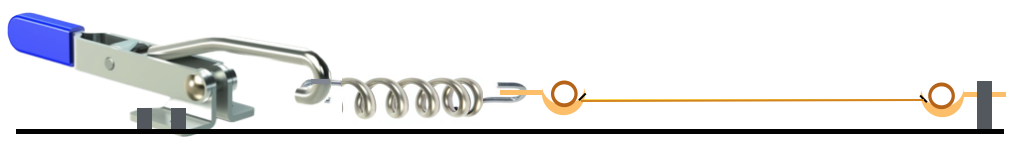
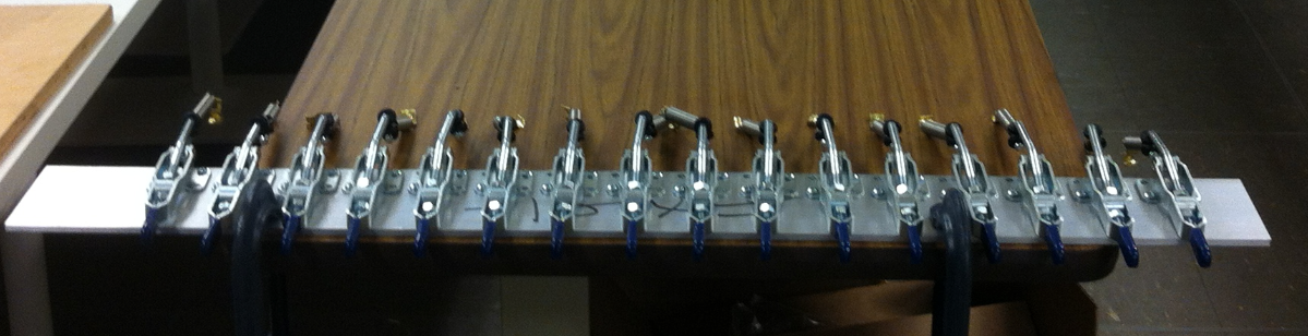
Once a wire has been prepared, the operators manually remove it from the machine by lifting the rings from the winding machine’s pins. The wire is then strength-tested. Each individual wire is placed on a tensioning station, where a tension of 24.5 N (2.5 kg) (more than three times the nominal TPC tension) is applied for ten minutes. This ensures that the wire preparation has not caused any weaknesses that could result in a breakage later on. Figure 9 shows the wire tension testing station, where springs mounted on levers create the force equivalent to 24.5 N on the wires when the lever is completely pulled down. One extremity of the wire is attached to the spring and the other one is fixed to the station.
|
 |
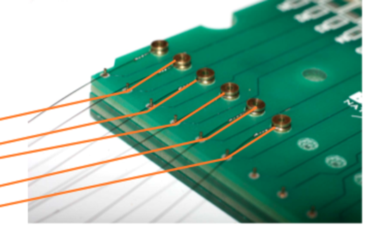
Having controlled the quality (strength) of each wire, the wires are placed manually in wire carrier modules shown in figure 10. To ensure good electrical contact to the wires, two rows of pins are used for the Y board, where each wire makes an -shaped bend between two pins (shown in figure 5). A single row of pins are used on the U V boards, since the wires are pulled against the pins at a 60 degree angle which ensures good contact. The board spacer and cover are installed and the board is closed. The assembled board is then placed in a stand for stress-testing, and a tension of 24.5 N per wire is reapplied to the fully populated board for 10 min. to ensure that the wires have not been weakened during the board assembly process. Finally, the assembled wire boards are placed into custom-made storage boxes where they remain until their installation on the TPC frame.
|
|
4 Tests and quality controls of the wires and the boards
One of the biggest risks to a TPC is that a wire might break after installation in a sealed cryostat filled with liquid argon. If even one of the 8256 wires happens to break once installed, it could short-circuit a significant portion of the signal wires if the broken wire makes contact with neighboring wires. In the worst case scenario, a broken wire could short-circuit the entire TPC if it were to make contact with the cathode plane where the high voltage is applied. Re-opening the cryostat to repair a broken wire would be both time-consuming and expensive, causing serious problems to the experiment. In order to ensure that no wires break after their installation, a series of tests are performed to understand the wire limitations.
Every aspect of the wire preparation was previously studied carefully to optimize the quality of the wires. The wire diameter, number of twists on the brass rings, the twisting angle and the post-preparation tests were all studied in great detail. The different tests and studies are presented in this section.
4.1 Wire strength and breakloads
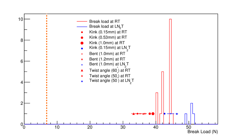
It was found that 150 m wire diameter was sufficient to safely withstand the TPC nominal tension of 6.86 N. The wire manufacturer reports a breakload of 42.83 N, which is over six times the TPC nominal tension. Tests to verify the wire breakload are performed and the results for 20 wires are shown in figure 13. At room temperature, the wire breakload measured of 42.9 1.5 N is in agreement with the vendor specifications. At liquid nitrogen (LN2) temperature, four wires were tested and the measured breakload of 50.4 0.9 N is over seven times the nominal tension.
4.2 Wire strength and breakloads of damaged wires
Defects or damages on the wires may reduce the breakload considerably. One
type of damage that can occur is if the wire gets kinked. To test the effect of kinks on the breakloads, single wires are kinked using pins of three different diameters (0.15 mm, 0.53 mm and 1 mm). The
range of diameters tests the effect of sharper kinks. The results of these
tests on three wires at room temperature and one wire at LN2 are summarized in figure 13. The breakload decreases by as much as 20% for small-diameter kinks. As expected, the sharper the kink, the greater the reduction in breakload. The breakload of damaged wires is also higher
in LN2 than at room temperature. In MicroBooNE, visual inspection was in place at several stages of the procedures to remove any kinked wires, therefore these extreme cases should not be present in the TPC. However, if several visual inspections missed a kinked wire, these results show that the safety margin was above five times the nominal tension at room temperature and above six times the nominal tension at LN2.
Another effect to consider when studying wire breakage is the effect of bending wires. For the U and V planes of the TPC, the wires are bent around 1 mm pins on the wire carrier boards, angled at 60∘ once installed in the TPC (see figure 11). Tests are performed to understand if bending a wire around a small object may reduce its breakload. To perform these tests, single wires are bent at 60∘ around pins of 1 mm and 1.2 mm in a way similar to how they are bent around the pins on the wire carrier boards for both room and LN2 temperatures. The results of these tests are also summarized in figure 13. As expected, the breakload decreases with the pin diameter and a bent has a less dramatic effect than a kink for the wire strength. For the 1 mm pin used in MicroBooNE, the breakload measured was over five times higher than the nominal tension at room temperature and near 6.5 times the nominal tension at LN2 temperature.
|
4.3 Effects of wire termination and attachment
The winding of the wires around the brass rings is also studied in order to optimize the number of twists and the twist angle. It is found that 6 twists are satisfactory to combine maximal strength and minimal length inside the carrier board. The angle at which the winding machines twist the wires is investigated; figure 12 shows two different twist angles of 50∘ and 60∘. The twisting angle tests results of two individual wires at room temperature and one wire at LN2 temperature are shown in figure 13. The 10% increase in breakload going from 60∘ and 50∘ at room temperature is over five times the nominal tension and over 6.5 times for LN2 temperature. The 50∘ angle was therefore used for MicroBooNE.
|
|
4.4 Effect of cold temperature shock
A final test is performed to see the effect of a very rapid change from room temperature to LN2 temperature on a fully-populated wire carrier board. This test uses pre-assembled Y plane wire boards placed under different tensions equal to or above the nominal detector tension. The tensioned (or over-tensioned) boards are then plunged into a LN2 bath to test if any wires will break. The different tensions applied to the wire assemblies during the test are 6.86N/wire (nominal TPC tension), 10.4N/wire, 12.4N/wire, 10N/wire and 18 N/wire (over 2.5 times the nominal tension). No wire breakage is observed for any of the applied tensions.
4.5 Discussion of the tests performed
The tests show that extreme conditions applied to the wires reduce the breakload. However, the minimum breakload observed in all of these tests is 33.3 N at room temperature. This tension is still almost five times higher than the nominal tension applied in the TPC (6.86 N). In LN2 (77K), the lowest breakload observed is 42.63 N, which is more than six times the nominal tension. Since the TPC is immersed in LAr (87K), it is therefore clear that the safety margin is sufficient to prevent wire breakage, even in the case of unnoticed damage to a wire. The quality assurance procedures described earlier ensure that all wires and wire carrier boards are systematically tested and inspected before installation, greatly reducing the risk of dramatic damage to the wires. The decision to sample only a small number of wires for these tests was made partly on experience from the previous ICARUS detector [4], that did not observed wire breakage after the detector assembly (over ten years) and from MicroBooNE collaborators handling wires in many different conditions without observing breakage.
5 Wire installation
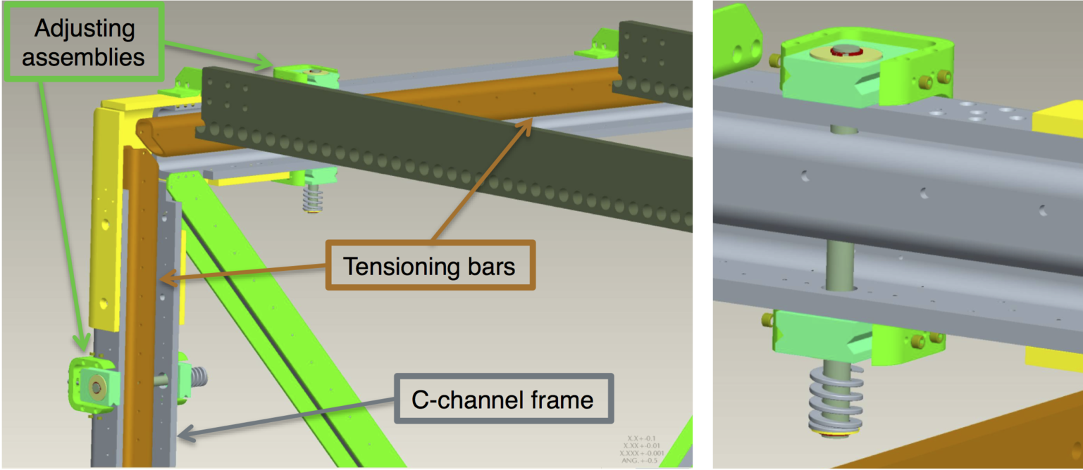
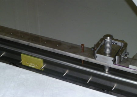
The wire carrier boards attach to tensioning bars that are held inside a C-channel frame, shown in the renderings of figure 14. The exact positions of the tensioning bars are controlled by adjusting assemblies that allow a small amount of pitch, roll, and yaw in each of the bars and many tensioning screws (not shown in these figures). There are a total of 12 tensioning bar segments, and these are grouped in four spans: two horizontal spans (top and bottom of the anode frame) which are each constructed from 5 adjoining segments, and two vertical spans (upstream and downstream sides of the anode frame) which are each a single tensioning bar segment. There are 24 adjusting assemblies; two per tensioning bar segment. The adjusting assemblies allow fine-tuning during the installation and initial alignment of the wire planes, but the bars are eventually fixed in place and tension on the wires is applied by bronze tensioning screws, shown in figure 15.
|
 |
 |
Before installing any wires, the tensioning bars must be squared and aligned. This is done with the help of a team from the Fermilab metrology group to adjust the bars within the C-channel frame such that the top and bottom horizontal bars are parallel to each other, the upstream and downstream vertical bars are parallel to each other, horizontal bars meet vertical bars at right angles, and all four sides lie in a plane that is parallel to the cathode plane. The angles of the four corners of the frame were all within 90.0 0.2∘ and the flatness of the frame surface was within 0.5 mm. The wire carrier boards are installed after this alignment, and upon completion of the wire plane installation, tension on the wires is tuned to the desired value by tightening the tensioning screws to apply force on the tensioning bars. The tensioning process is described in more detail in section 5.3.
In preparation for installing the wires on the TPC, a trial installation using sparsely populated wire carrier boards is undertaken. This trial installation, known as the mock installation, is described in this section, followed by a description of the full installation of real wires.
5.1 Mock installation
The mock wire installation is designed to test the installation procedures with a set of full-length prototype wires, allowing the installation team to practice handling techniques and to identify areas in which procedures should be modified before attempting to install the real set of 8256 wires. This trial run allows the team to detail the full installation and tensioning procedure of the U, V, and Y wire planes.
Wires for the mock installation are prepared using the wire winding machine shown in figure 6. The only difference between the mock wires and the real wires is the fact that the mock wires are entirely stainless steel, while the real wires are stainless steel with copper coating and gold flash. All other specifications are identical, and the mock wire carrier boards are assembled according to the same procedures detailed in section 3.
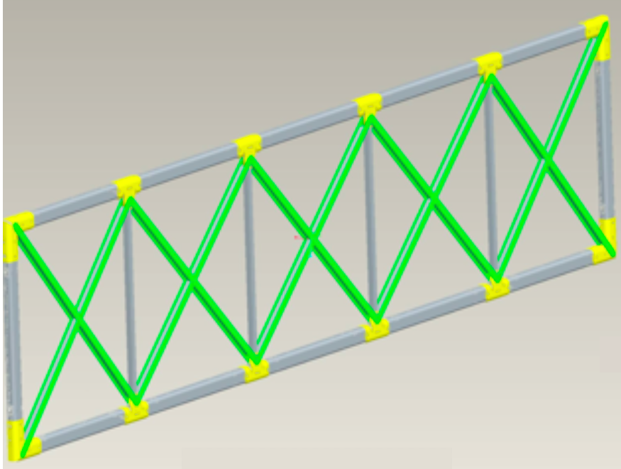
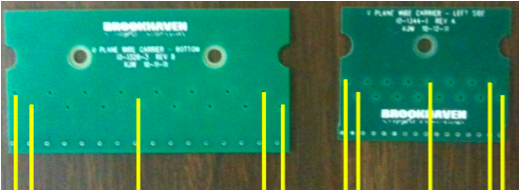
In order to reduce the total amount of time spent winding wires and producing boards, only five wires are installed per wire carrier board, as shown schematically in figure 16. These sparsely-populated wire carrier boards allow the team to fully test the installation procedures for each of the multiple wire planes (U, V, and Y) in the correct order and to understand and test the wire tensioning procedure along the full length of the TPC. The reduced number of wires per carrier board does not affect the installation or tensioning procedures.
|
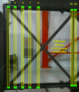
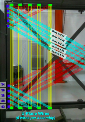
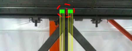
Figure 17 (left) shows the layout of the Y plane boards for the mock installation. The mock board installation locations are chosen to cover the areas of the anode frame that are the most challenging to install (corners) and the areas that are most critical for tensioning (joints), while covering as large a fraction of the anode frame area as possible. Boards located near the joints in the anode frame, where two stainless steel tensioning bars adjoin, are an example of an area that is critical for consistent wire tensioning. The vertical wire carrier boards labeled as “21” and “22” in figure 17, shown in more detail in figure 18, are installed to test how the joints behave and how the wire tensions on adjacent boards change under tensioning in these regions. After the installation of the Y plane wires, the V and U planes wire carrier boards stack onto the installed Y-plane boards as shown in figure 17 (right). The shortest wires of the U and V plane are in the corners of the anode frame. The longest wires, attaching to the anode frame from one corner and extending to the opposite corner (shown), are stacked on empty spacer boards to achieve the correct plane-to-plane spacing. The main objective of installing these particular wire carrier boards is to practice handling these 5-meter-long wires.
|
 |
|
The mock wire installation successfully tested the procedure and highlighted steps that required special care; the quality assurance steps and installation plan were modified to reflect the lessons learned here. We changed the initial position of the tensioning bars to facilitate the installation of the wires and we increased the number of people handling the boards. This activity also trained installers with a technical rehearsal that ensured smooth and coordinated operation during the full wire installation.
5.2 Full installation
The full set of wires are installed following the plan developed and tested in the mock wire installation and took place inside of an enclosed assembly area outfitted with HEPA filter fans that provided a slight positive pressure relative to outside the assembly area. This provided a clean environment for the assembly, although the room did not have a clean room rating. After the initial alignment of the tensioning bars, the entire structure is cleaned with lint-free wipes and ethyl alcohol. Then the wire carrier boards are installed serially, starting with the Y plane, followed by the V plane, and finally the U plane. The wires on each wire carrier board are visually inspected for damage before installation. In the case that a damaged wire is found, the board is partially disassembled, the damaged wire is replaced with a new wire, and the board reassembled and tested again. Replacement of wires was only necessary in a few cases where the wire sustained minor damage during installation. In total, it took approximately one week to install all three planes of wires.
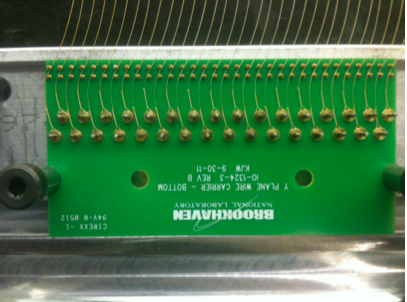
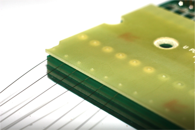
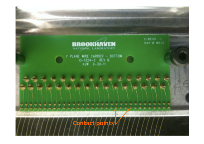
Upon completing installation of each wire plane, a simple continuity test is performed for each wire in that plane to ensure good electrical contact between the wire and the carrier board pins, shown in figure 19. Before beginning installation of the next plane, the wires in the installed plane are also examined by eye, looking for any kinked wires, abrasions, or other forms of damage. The final step, after all wire planes are installed and inspected, is the addition of cover plates that secure the stacked wire carrier boards to the tensioning bar, shown in figure 20.
 |
 |
5.3 Wire tensioning
Proper tension of the wires is important for safe commissioning and successful operation of the experiment. It is especially important to account for wire tension during the initial cool-down phase of the experiment. During this phase, the detector moves from a state where the cryostat is filled with room temperature air to the state where it is filled with cold gaseous argon, and although the wires and the TPC frame have similar thermal expansion coefficients, the thin wires are subject to faster cool-down, and therefore faster thermal contraction, than the rest of the massive stainless steel TPC frame. If the wire contraction occurs much more quickly than the frame contraction, wires could break or become permanently stretched. For this reason, a thermal gradient limit is set during cool-down, requiring that the temperatures at the top and bottom of the TPC frame never differ by more than 20 K. The nominal 0.7 kg (6.86 N) of tension established for the wires is small enough to prevent wire breakage during cool down, but large enough to limit the maximum wire sag due to gravity to less than 0.5 mm for any 5-meter-long U or V wire.
Tension is put on the wires by adjusting the bronze tensioning screws to push on the tensioning bar, as shown in figure 15. Since the wires are grouped in sets of 16 or 32 on the wire carrier boards, and the wire carrier boards are grouped together on adjoined rigid tensioning bars, it is not possible to fine-tune the tension of individual wires. Instead, it is necessary to adjust the positions of the tensioning bars to achieve as uniform a map of wire tensions as possible across the full set of wire carrier boards.
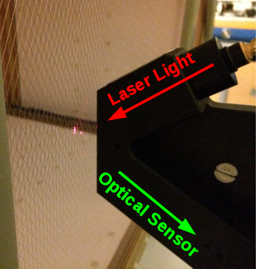
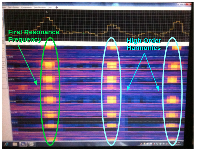
The tensioning process is necessarily iterative, as the adjustments in one area of the TPC anode frame affect tensions in other areas due to the angled U and V wire planes. It was realized during this process that the MicroBooNE design did not allow to adjust the tension of all the wires to the level of the original requirements, due to limitations of the tensioning system. This method also demonstrated that in the MicroBooNE design, it is not physically possible to measure the tension of all the wires because of mechanical constraints where the apparatus cannot access the wires. The tensions of approximately 95% of the wires were measured with a custom-designed apparatus designed and constructed by the Physical Sciences Lab of University of Wisconsin-Madison [6, 7, 8], shown in figure 21. This device consists of an LED that is focused onto a wire, and a photodiode that measures light reflected from the wire. When the wire is lightly strummed, the output of the photodiode is fed into a laptop with a spectrum analyzer that performs a fast Fourier transform to convert the pulses into the frequency domain, and the peak frequency is recorded for each board/wire measured. The frequencies measured can be converted to tensions for known wire lengths.
|
Tension is measured using the characteristic resonance frequency of each wire, which is related to its length ( in ), tension ( in ), and linear mass density (, measured to be 0.00014 g/cm) through equation 5.1.
| (5.1) |
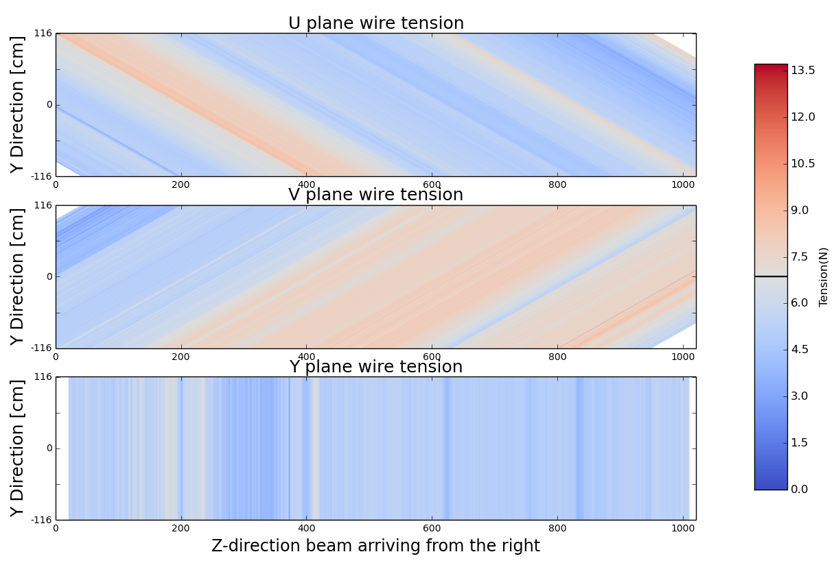
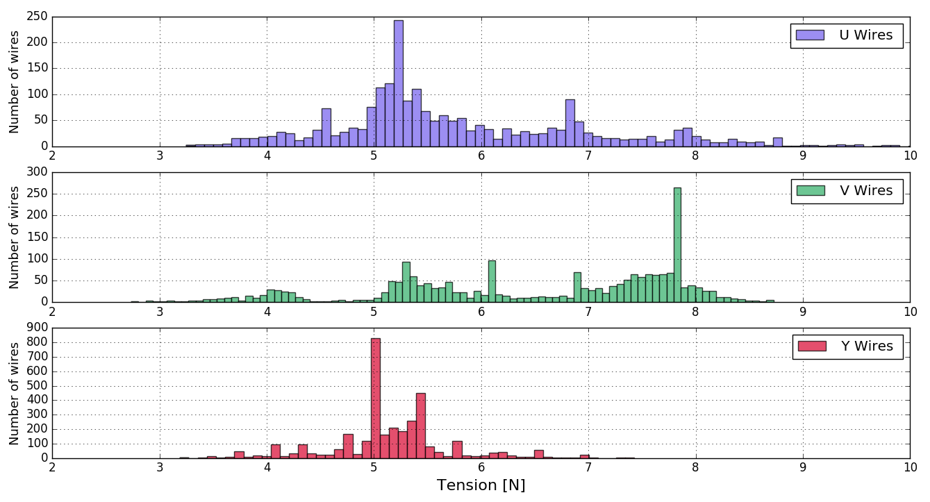
Figure 22 shows the tension measurement results for each of the three planes. Tensions were measured for 2256 of the 2400 U wires, 2256 of the 2400 V wires, and 3312 of the 3456 Y wires, corresponding to 94.8% of the wires installed in the detector.
The overall average tensions of the U, V, and Y planes, respectively, are
5.78 N, 6.51 N, and 5.15 N. Table 1 also shows the values for the minimum and maximum measured tension values in each wire planes. Since it was physically impossible to adjust all the tensions as originally planned, lower-tension values were preferred to over-tension ones to
prevent wire breakage during cooldown, resulting in an overall average
slightly lower than the 6.86 N nominal value. These results can be related to the discussion in section 4. The highest wire tension measured in each plane after the tensioning procedures is now 5.7/4.0/4.9 times lower than the lowest breakage tension value observed in the tests for the Y/U/V plane respectively at LN2 temperature. This was considered satisfactory for MicroBooNE. We also looked at the expected sag for the wires with different tensions. The sag depends on the length of the wire as well as the tension applied to it. It was found that the largest possible sag was around 0.86 mm. This is slightly larger than the required 0.5 mm, but because of the mechanical constraints of the tensioning devices, this was judged satisfactory. This slightly larger sag value could affect the spatial resolution, however, it is mitigated by the redundancy of the three planes, allowing for at least two planes, where the sag is meeting the original requirements.
| Plane | Minimum tension (N) | Maximum tension (N) | Average tension (N) |
| Y | 3.19 | 7.43 | 5.15 |
| U | 3.25 | 10.71 | 5.78 |
| V | 2.74 | 8.73 | 6.51 |
 |
|
6 Conclusion
The MicroBooNE TPC anode readout wire planes were assembled, installed, and tested according to the procedures described in this document. The use of semi-automatic wire winding machines considerably helped the preparation of the individual wires. A strict quality assurance program was followed to ensure that the wires were intact at every step of the process. This was vital to the success of the plane construction, since a broken wire could have had disastrous consequences on the experiment. Inspection of the wires inside the cryostat few months after the transport of the MicroBooNE cryostat also demonstrated the integrity of the planes [10]. Several tests were performed at different stages of the process to inform design decisions. It was found that tensioning all the individual wires to a desired value was unachievable with the tensioning bars and tension adjusting assemblies used for MicroBooNE. The method described in this paper has some limitations but is appropriate for any medium-sized LArTPC. For larger scale detectors, a more automated process should be considered. The procedures described here can inform the design of future LArTPCs such as SBND [11] and DUNE [12].
Acknowledgments
We would like to acknowledge the immense technical support from Tom Hurteau as well as the help from undergraduate and graduate students for the wire winding from Yale University: Kinga Partyka, Christina Brasco, Ben Elder and from Syracuse University: Thomas Badman, Deborah Noble, David Norcross. We gratefully acknowledge the Fermilab TRAC program, which provided funding for two of our authors. This paper is based upon work supported by the U.S. Department of Energy and the U.S. National Science Foundation. R. Guenette is now supported by the UK Science and Technology Facilities Council and A.M. Szelc is now supported by the UK Royal Society. Fermilab is operated by Fermi Research Alliance, LLC under Contract No. DE-AC02-07CH11359 with the United States Department of Energy.
References
- [1] The MicroBooNE Collaboration, Technical Design Report, http://www-microboone.fnal.gov/publications/TDRCD3.pdf
- [2] C. Rubbia, The liquid argon time projection chamber: a new concept for neutrino detectors, CERN-EP-INT-77-8, 16 May 1997
- [3] The MicroBooNE Collaboration, Design and Construction of the MicroBooNE Detector, arXiv 1612.05824
- [4] S. Amerio et al. (The ICARUS collaboration), Design, construction and tests of the ICARUS T600 detector, Nucl. Inst. Meth. A527 2004 329-410.
- [5] S. Rescia and V. Radeka, Noise model of sense wire for large liquid argon time projection chambers: Theory and experiment, IEEE NSSMIC, 5873886, 2010
- [6] Physical Sciences Lab - University of Wisconsin-Madison. http://www.psl.wisc.edu
- [7] Calvetti, M. et al.,A Computer Aided System for Mwpc Wire Tension Control,Nucl. Instrum. Meth. 174 1980 285-289
- [8] Baldini, W. et al., A Laser Based Instrument for MWPC Wire Tension Measurement, 2007LHCb-2007-120 CERN-LHCb-2007-120
- [9] Sectrum Lab: http://www.qsl.net/dl4yhf/spectra1.html,
- [10] B. Carls et al., Design and operation of a setup with a camera and adjustable mirror to inspect the sense-wire planes of the Time Projection Chamber inside the MicroBooNE cryostat JINST 10 T08006 2015
- [11] http://sbn-nd.fnal.gov
- [12] http://www.dunescience.org