Artificial circumzenithal and circumhorizontal arcs
Abstract
We revisit a water glass experiment often used to demonstrate a rainbow. On a closer look, it also turns out to be a rather close analogy of a different kind of atmospheric optics phenomenon altogether: The geometry may be used to faithfully reproduce the circumzenithal and the circumhorizontal halos, providing a missing practical demonstration experiment for those beautiful and common natural ice halo displays.
I Introduction
Light which falls onto a transparent thin-walled cylinder (e.g. a drinking glass) filled with water gets refracted. Several ray paths may be realized through what then effectively represents a cylinder made of water. Light may either illuminate and enter through the side of the cylinder, or may enter through the top or bottom interfaces, depending on the angle and spot of illumination. Indeed, in the former situation, i.e. illumination from the side and under a shallow inclination angle reveals a rainbow in the backwards direction. The reason being that the geometry mimics the incidence plane geometry of a light path though a spherical raindrop: Refraction, internal reflection and a second refraction upon exit, all occurring at the cylinder’s side wall, produce the familiar observable rainbow caustic in the backwards direction at around towards the incidence light source.Greenler1980 ; Casini2012
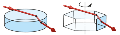
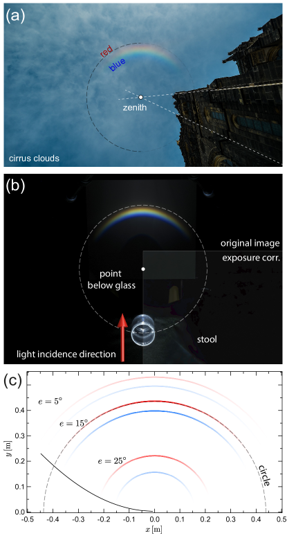
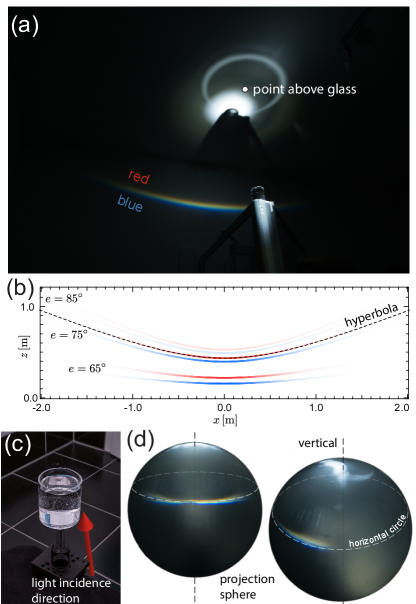
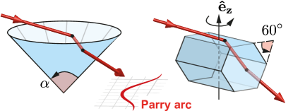
Now, returning to the initial claim, we consider illumination of the glass through the top water-air interface. If the angle of incidence is shallow enough, light may exit through the cylinder’s side wall. Contrary to common belief,Gilbert1920 (cf. also blogs etc. found via an internet search for “glass water table rainbow”) this situation is not related to the rainbow. Instead, this geometry equals the average geometry of light paths through an upright hexagonal ice prism, entering through the (horizontal) top face and leaving through either of its six (vertical) side faces, cf. Fig. 1. The averaging meant being over different prism orientations as indicated in the figure. This, in turn, is what causes the natural atmospheric phenomenon known as the circumzenithal arc (CZA) halo,Bravais1847 ; Humphreys ; Ticker ; Wegener ; McDowell1979 ; Greenler1980 ; TapeBook ; TapeJarmo2006 ; atmosHP an example of which is shown in Fig. 2(a). In the experiment, an analogous curved spectrum is observed when the refracted light is projected on the floor (the horizontal plane) some distance from the cylinder,Distance see Fig. 2(b).
Similarly, illuminating the glass at a very steep angle at its side, the light may enter through the side wall and leave through the top surface. Now, apart from top and bottom being reversed, this geometry equals the average geometry of light entering a rectangular (vertical) side face of a hexagonal plate crystal and leaving through its bottom (horizontal) hexagonal face. This is the situation corresponding to the natural halo phenomenon known as the circumhorizontal arc (CHA).Bravais1847 ; Humphreys ; Ticker ; Wegener ; Greenler1980 ; TapeBook ; TapeJarmo2006 ; atmosHP
Anecdotally, it appears puzzling why Huygens, who was the first to establish an extensive quantitative framework for halos based on the (false) assumption of refracting cylinders, did not conceive of this CZA mechanism and instead invoked a more complicated one.Puzzle
We will detail each experimental setup and show how to arrive at a quantitative description of several aspects of the artificial halo analoga, rederiving well-known expressions from the natural atmospheric optics ice halo phenomena. For ideal experimental results, one may use a round reflection cuvette. However, a beaker or any other cylindrical glass and a focusable LED flashlight (source of parallel white light) will work just fine.
II Artificial circumzenithal arc
We begin with the artificial CZA, for which a ray is assumed to enter through the top air-water interface and to leave the cylinder through its side wall, cf. Fig. 3(a)-(c). At the first interface, the ray changes its inclination towards the horizontal plane according to Snell’s law. We denote complementary angles by a subscript , such that for instance , see Fig. 3(b). Thus, we have , with an associated transmission coefficient according to the Fresnel equations. When later discussing intensities, we will consider polarization-averaged transmission coefficients only, although this approach will not strictly be valid for the second refraction due to the partial polarization upon the first refraction.
The second (skew-ray) refraction now occurs under a geometry that may be decomposed into two partsBravais1847 ; Humphreys ; Ticker ; Wegener ; Koennen1983 ; Selmke2015 : One in the horizontal plane (i.e. as seen from the top, cf. Fig. 3(c)) and described by an effective index of refraction , Bravais’ index of refraction for inclined rays, and a second inclination refraction described by the actual material’s index of refraction . The appropriate effective index of refraction reads:neff
| (1) |
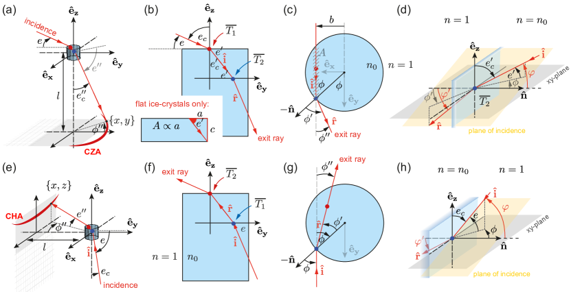
The exiting ray, which hit the cylinder’s side wall under a -projected incidence angle of (to the normal), is thus deflected in the horizontal plane by , where Snell’s law connects the latter two angles via . The inclination angle to the plane changes according to , such that overall the exit angle to the vertical becomesBravais1847 ; Humphreys ; Wegener ; McDowell1979
| (2) |
Then, referring to the experiment’s setup and coordinates as defined in Fig. 3(a), one finds for each light source inclination angle the deflected rays to lie on a curve . This CZA curve may be parametrized by the angle , see Fig. 3(c), as
| (3) |
wherein , i.e. . Eq. 3 describes a circle, see dashed line in Fig. 2(b),(c). However, it turns out that only a segment of the circle is attainable by the exiting rays due to the occurrence of total internal reflection. The solid black line in Fig. 2(c) shows this limit. The critical internal angle of incidence may be found from , such that marks the onset of total internal reflection. Herein is a function of which is a function of . One findsBravais1847 ; Wegener
| (4) |
which translates into a corresponding azimuthal limit of the (projected artificial) CZA.
A similar reasoning leads to the existence of a critical elevation angle above which the internal second refraction becomes a total internal reflection, , Eq. (2), even for where is lowest. Equivalently, one may set and solve Eq. (4) for to arrive at:Bravais1847 ; Humphreys ; Wegener ; McDowell1979
| (5) |
Eq. (5) shows that at around even the last glimpse of the red (, i.e. less refracted than blue ) part of the artificial (water) CZA disappears. For ice, taking , the corresponding critical solar elevation above which this halo can no longer be observed is .Bravais1847 ; Wegener ; Humphreys ; Ticker ; McDowell1979 Eq. (5) also shows that any material with , i.e. glass, will not produce a CZA (nor a CHA).Tammer1998 ; Vollmer2014 ; Selmke2015 ; Borchard2015 For this reason alone, and in order to not have to construct a water-filled hexagonal prism, it is nice to have a simple analog demonstration experiment to overcome this practical limitation. The full azimuthal width of the CZA is and is an increasing function of the elevation, starting from and approaching a half-circle, i.e. , for . In this limit, Eqs. (4) and (5) show that light emerges only from a small section around , where the effective index of refraction diverges whereby the exiting refraction deviates rays at a right angle towards the left and the right.
The complementary angle of the final exit ray’s inclination, Eq. (2), corresponds to the angular distance to the azimuth of the natural CZA halo phenomenon.CZAnat ; Wolfram ; note46 This angular distance is independent of the azimuth (or ), such that the natural CZA appears as a true circle around the zenith (Fig. 2(a)),Bravais1847 ; Humphreys ; Wegener just as the artificial CZA is a circle in the -plane (Fig. 2(b)). One may also observe, both in natural displays of the phenomenon as well as in the experiment, that the angular width of the visible spectrum, i.e. the chromatic angular dispersion , remains roughly constant at (which may be compared to the dispersion of the primary rainbow). Only at very small inclinations a broadening is observedWegener ; McDowell1979 before the shrinking CZA eventually disappears as it converges towards the zenith (or the point below the cylinder), cf. Fig. 2(a),(c).
III Arc Intensity
Without treating the situation in full detail, a description of the approximate intensity along the azimuthal coordinate requires several key factors to be considered:McDowell1979
-
•
, transmission at the first interface,
-
•
, transmission at the second interface,
-
•
, a geometric factorcrosssection ,
-
•
, , i.e. a ray bundleling factor,
-
•
, a chromatic dispersion factor.
-
•
, atmospheric attenuation (natural halo only)
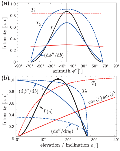
The cross-sectional factor takes the projected surface of the top face into account which admits refraction along the ray path described by the internal angle , see dashed area in Fig. 3(c).crosssection The ray bundleing factor is a caustic intensity factor for the cylinder experiment and a fake caustic intensity factor for the natural counterpart.Koennen1983 Its concept is similar to that of the rainbow caustic,Berry2015 and accounts for the predominance of certain deflection directions as outcomes of the refraction of an incident parallel bundle of rays. The fact that more rays experience a small azimuthal in-plane refraction is then captured by this factor peaking around . However, in this case no divergence of the intensity appears, i.e. this factor remains finite at all times. The chromatic dispersion factor accounts for the changing width of the arc, such that its apparent brightness is . Overall then,
| (6) |
cf. Fig. 4. This expression quantifies the observed azimuthal decay in intensity away from the forward direction and towards zero for due to the second interface’s transmission going smoothly to zero as the limit of total internal reflection is reached. The transmission coefficient (blue dashed line in Fig. 4(a)) upon the second refraction depends on the actual angle to the normal, cf. Fig. 3(d), which is given by .T2angle The parametric curves in Fig. 2(c) have been shaded according to this intensity function and match the appearance of experimentally observed CZAs projections and natural halo displays well.
Plotting the intensity in the forward direction at the position of maximum CZA intensity (at ) as a function of the elevation (inclination), , one observes a wide peak, see thick black line in Fig. 4(b). This means that for some solar elevations (or light source inclinations) the (artificial) CZA is brighter as compared to others. For water and ice (including the atmospheric attenuation), this peak occurs at around and , respectively. For ice then, this value corresponds to the elevation at which the CZA is best observable, see for instance Refs. Humphreys ; Wegener ; McDowell1979 ; atmosHP . For water, this is the light source inclination for which the experiment produces the brightest CZA projection. Both (red dashed line) and the geometric factor (red solid line) describe the decay towards . For the natural halo, also the atmospheric attenuation affects the decay when the sun is low and dimAirMass . At the other end of the curve, (blue dashed line) along with the ray bundleing factor (blue solid line) describe the decay towards . The decrease of the ray bundleling factor may be understood as follows: The inclination angle increases for increasing elevation angles , such that the effective index of refraction , Eq. (1), increases as well (eventually diverging as we have seen). This in turn causes the exit rays which are deflected by to sweep more rapidly across the forward () direction as the impact parameter crosses the symmetry axis. Accordingly then, the bundleling of rays in the forward direction is reduced as increases.
IV Artificial circumhorizontal arc
We now turn to the artificial CHA, see Fig. 5(a), for which the first refraction is the side wall of the cylinder in the experiment, see Fig. 3(e)-(g). Accordingly, it is this refraction which must be treated according to the inclined skew-ray theory of Bravais. Again, we decompose the problem into two parts: The material’s index of refraction directly determines the change in the inclination angle, , and the in-plane refraction (i.e. as seen from above) follows , with the effective index of refraction beingBravais1847 ; Wegener ; Humphreys ; Ticker ; Koennen1983 ; Selmke2015
| (7) |
The second refraction at the top water-air interface only changes the inclination towards the horizontal, , and no in-plane refraction takes place since the refracting interfaces’ normal is vertical. One finds , which is the analog of Eq. (2). Referring to the experiment’s setup and coordinates as defined in Fig. 3(e)-(g), the curve described by the artificial CHA on the vertical wall is parametrized by the angle as:
| (8) |
where . Since , and is a constant independent of ,hyperbola the artificial projected CHA for each inclination is a hyperbola in the -plane, see Fig. 5(b). If the projection were onto a sphere, the natural CHA halo’s geometry of a circle segment parallel to the horizon (i.e. at constant elevation) were to be recovered, cf. Ref. SelmkeSelmke2015 . The angle to the surface normal which determines the transmission coefficient is , see Fig. 3(h). The transmission coefficient corresponds to the second refraction changing the elevation only. The intensity may then be analyzed along the same lines as for the CZA, but with the cross-sectional factor being .CHAint Again, this approach was used to set the transparency of the curves in Fig. 5(b). We find that the CHA is brightest at around in the experiment and for the natural halo, whereas azimuthally it decays to zero for (grazing incidence) where accordingly .Bravais1847 ; Wegener The corresponding full azimuthal width of twice that value therefore ranges from in the experiment and for the natural ice halo phenomenon. The half-circle limit is reached in the reverse situation as compared to the CZA, i.e. here for grazing incidence with (as compared to grazing exit for the CZA). The natural CHA only forms when the inclination is larger than (iceWegener ) and (water), where the critical inclination as determined for the CZA, Eq. (5), can be reused. The halo rises in altitude (elevation) as the sun approaches the zenith ( angle of incidence onto the side face), where it will be .Bravais1847 ; Ticker The experimental CHA reproduces these behaviors closely.
V Conclusion & Outlook
A thorough analysis of a very simple experiment, namely a glass filled with water illuminated under various directions of incidence, provides a rich phenomenology. We have shown that the emerging projections of light closely correspond to two natural atmospheric ice halos: the circumzenithal and the circumhorizontal arcs. The general angular characteristics derived and validated by the experiment also apply to their natural counterparts. This demonstration experiment may complement more complex ones based on spinning glass crystalsTammer1998 ; Greenler2003 ; Vollmer2014 ; Borchard2015 ; Selmke2015 ; SelmkeSelmke2015 . It also produces a purer spectrum as compared to a rainbow demonstration since, similar to the action of a prism, ideally no color-overlap occurs. The experiment may thus be used as a halo alternative to rainbow demonstrationsCasini2012 or as an illustrative example of skew-ray refraction.
We end with an outlook on similar experiments: One may use a water-filled martini / cosmopolitain cocktail glass as a refracting cone, cf. Fig. 6. By the same idea that led us to the CZA analogy, one may confirm (see Appendix B) that the average geometry of light entering through the top air-water interface and leaving through the lateral cone surface results in an analogy to Parry’s halo.Wegener ; Greenler1980 ; TapeBook Using a cocktail glass, one may find in addition an artificial parhelic circle due to external reflections from the stem of the glass as well as artificial heliac arcsTapeBook due to external reflections by the conical surface. Likely, many more halo counterparts may be realized along the lines presented here.
Appendix A Colors
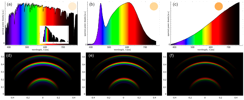
Perceived colors were computed as follows: First, the tristimulus values (trichromatic color space coordinates) are computed via the CIE standard calorimetric observer color matching functions and from the spectral radiance , e.g. . We assumed a linear relation between this quantity and the spectral power density of a given light source. For a single wavelength, a narrow (FWHM ) Gaussian line spectrum was chosen. Then, a linear transformation (a matrix product) converts these to linear RGB values, , which subsequently are converted to the common sRGB color space values through a non-linear transformation. Finally, the values are normalized to give a valid sRGB color. The required data can be found online at http://www.cie.co.at and https://en.wikipedia.org/wiki/SRGB. The hereby obtained sRGB color values for each wavelength were multiplied by an intensity factor to recreate the azimuthal intensity decay of the correspondingly colored CZH segments corresponding to .
Corresponding computation assuming a solar spectrum, a LED light source spectrum and a n incandescent light bulb spectrum along with the dispersion of water are shown in Fig. 7 for different elevations. They may be compared to displays computed with dedicated halo simulation software.HaloSim Note that in the experiment colors may superimpose (and green disappear) if the projection distance is too small.
Appendix B Artificial suncave Parry arc
We keep the notation of Fig. 3(a), where we imagine the cylinder being replaced by the cone of Fig. 6, and acknowledge that for the second refraction (the first being analogous to the CZA) the normal vector is now for the cone’s lateral surface. The incidence vector makes an angle to this normal. The refracted angle is then determined by . To get the refracted ray, one may rotate the external unit vector according to the right hand rule by about an axis perpendicular to the plane of incidence, defined by the unit vector . This can be done via Rodrigues’ rotation formula, yielding the exiting ray’s unit direction vector . The line described by this unit direction vector and starting at a height above the origin (at the position of the glass) intersects the horizontal -(projection-)plane at the point . This is the artificial projected suncave Parry arc parametrized by . The complementary angle to the elevation is when , and negative that value when , signifying a Parry arc beyond the zenith with (in front of the cocktail glass when viewed from the direction of incident light). The azimuths are for . The arc appears concave towards the shadow of the glass (corresponding to the sun position and being suncave as its natural counterpart), and the angular distance to this shadow, , corresponds to the distance to the sun for the natural halo. The hereby obtained angular coordinates agree with e.g. Ref Wegener . Alternatively then, the projected artificial Parry arc curve on the floor may be computed via Eq. (3) if the following replacements via the variables of Wegener’s chapter 12Wegener are made: and and Wegener’s being the parametrization. Using glasses with smaller apex angles (walls becoming increasingly vertical / cylinder-like), the arc inverts from suncave to sunvex and approaches the CZA in the limit .
References
- (1) C.J. Lynde, Gilbert light experiments for boys (New Haven, Conn., The A. C. Gilbert Co., 1920), Experiment No. 94
- (2) G. Casini and A. Covello. “The ”rainbow” in the drop,” Am. J. Phys. 80(11), 1027–1034 (2012).
- (3) R. Greenler, Rainbows, Halos and Glories (Cambridge U.P., England, 1980).
- (4) L. Cowley, website “atmospheric optics,” http://www.atoptics.co.uk/halosim.htm.
- (5) W. Tape, Atmospheric Halos (Antarctic Research Series. American Geophysical Union, Washington, D.C., 1994).
- (6) W. Tape and J. Moilanen, Atmospheric Halos and the Search for Angle x (American Geophysical Union, Washington, D.C., 2006).
- (7) R.S. McDowell, “Frequency analysis of the circumzenithal arc: Evidence for the oscillation of ice-crystal plates in the upper atmosphere,” J. Opt. Soc. Am. 69(8), 1119–1122 (1979)
- (8) A. Bravais, “Mémoire sur les halos et les phénomènes optiques qui les accompagnent,” J. de l’ École Royale Polytechnique 31(18), 1–270 (1847).
- (9) W.J. Humphreys, Physics of the air, 2nd Edition, (McGraw-Hill Book Company, Inc., New York and London, 1929).
- (10) R.A.R.. Tricker, Introduction to meteorological optics (Mills & Boon, London, 1970).
- (11) A. Wegener, Theorie der Haupthalos (L. Friederichsen & Co, Hamburg, 1926).
- (12) The distance must be much larger than the focal distance of the curved cylinder interface, , where is the cylinder’s radius. Practically, is fine.
- (13) HuygensHuygens1662 hypothesized horizontal cylinders of arbitrary in-plane orientation to describe what was at that time though to be a tangent arc to the circular halo.TapeJarmo2006 ; note46
- (14) C. Huygens, Oeuvres complètes Tome XVII: L’horloge à pendule de 1651 à 1666. Travaux divers de physique, de mécanique et de technique de 1650 à 1666. Traité des couronnes et des parhélies (1662 ou 1663) (ed. J.A. Vollgraff. Martinus Nijhoff, Den Haag, 1932). see arc THS in Fig. 22, §37, and its discussion.
- (15) M. Selmke, “Artificial Halos,” Am. J. Phys. 83(9), 751–760 (2015).
- (16) G. P. Können, “Polarization and intensity distributions of refraction halos,” J. Opt. Soc. Am. 73(12), 1629–1640 (1983).
- (17) Usually, the effective index of refraction is discussed for rays entering a dense material from air, i.e. Eq. (7).Bravais1847 ; Humphreys ; Ticker ; Selmke2015 For the inverse situation, note that refraction from to is mathematically equivalent to refraction from into . Eq. (1) follows by inverting the corresponding effective inverse index of refraction, .
- (18) WolframAlpha, Wolfram Alpha LLC, http://www.wolframalpha.com/input/?i=solar+elevation,+51.33065N,12.37595E,+24.10.2015,+1:04pm, Retrieval date: 07/05/2016
- (19) The ratio , where is the CZA diameter and the image width, may be used to extract the angular distance to the zenith, . This value is in agreement with Eq. (2), Wolfram and . was the focal length of the rectilinear projection lens and the APS- C sensors’ -dimension.
- (20) For the natural halo, the exit angle’s altitude, is close to tangentialBravais1847 to the circular halo, i.e. , where is the minimum deviation angle through a prism. However, it is not precisely equalHumphreys ; Ticker except for .
- (21) The factor only appears in case of the natural flat hexagonal plate crystals, see Ref. McDowell1979 .
- (22) M.V. Berry “Nature’s optics and our understanding of light,” Contemporary Physics 56(1), 2-16 (2015).
- (23) Air mass (solar energy), From Wikipedia, the free encyclopedia, https://en.wikipedia.org/wiki/Air_mass_(solar_energy), Retrieval date: 08/03/2016, , : spherical shell approximation.
- (24) To see this, consider the dot product of the incidence ray’s unit vector and the cylinder surface normal at the point of refraction, as shown in Fig. 3(a)-(d)
- (25) Fig. 3(e)-(h) shows that , and , where .
- (26) M. Selmke, S. Selmke “Complex artificial halos for the classroom,” Am. J. Phys. 84(7), 561-564 (2016).
- (27) M. Vollmer and R. Greenler, “Halo and mirage demonstrations in atmospheric optics,” Appl. Opt. 42(3), 394–398, 2003.
- (28) M. Vollmer and R. Tammer, “Laboratory experiments in atmospheric optics,” Opt. Express 37(9), 1557–1568 (1998).
- (29) M. Großmann, K.-P. Moellmann, and M. Vollmer, “Artificially generated halos: rotating sample crystals around various axes,” Appl. Opt. 54(4), B97-B106 (2014).
- (30) S. Borchardt and M. Selmke, “Intensity distribution of the parhelic circle and embedded parhelia at zero solar elevation: theory and experiments,” Appl. Opt. 54(22), 6608-6615 (2015).
- (31) To include the effect of the reduced projection intensity on the wall due to the inclination of the rays, one may further include a factor . We choose to ignore it here to be in line with the natural CHA intensity.
- (32) L. Cowley and M. Schroeder. HaloSim simulation program. http://www.atoptics.co.uk/halo/halfeat.htm.