A single-atom quantum memory in silicon
Abstract
Long coherence times and fast gate operations are desirable but often conflicting requirements for physical qubits. This conflict can be resolved by resorting to fast qubits for operations, and by storing their state in a ‘quantum memory’ while idle. The 31P donor in silicon comes naturally equipped with a fast qubit (the electron spin) and a long-lived qubit (the 31P nuclear spin), coexisting in a bound state at cryogenic temperatures. Here, we demonstrate storage and retrieval of quantum information from a single donor electron spin to its host phosphorus nucleus in isotopically-enriched 28Si. The fidelity of the memory process is characterised via both state and process tomography. We report an overall process fidelity %, a memory fidelity %, and memory storage times up to 80 ms. These values are limited by a transient shift of the electron spin resonance frequency following high-power radiofrequency pulses.
1 Introduction
In classical computation, memory is a trivial resource, implemented simply by making copies of digital information in long-lived memory hardware, and retrieving the information at later stages for further processing. In quantum computation, this is forbidden by the fundamental inability of arbitrary quantum states to be faithfully copied, as dictated by the no-cloning theorem [1]. Therefore, in the absence of additional resources or quantum error correction, the storage of a quantum bit (qubit) is limited by the intrinsic coherence time of the physical qubit that holds the information. ‘Quantum memories’ [2] surpass the storage limits of a given physical qubit by transferring the quantum information onto a ‘memory qubit’ which is less susceptible to environmental noise and dephasing, then returning the information to the preferred ‘processing qubit’ when required, once again allowing fast manipulation and/or readout. Alternatively, memory qubits can serve the purpose of storing a ‘flying qubit’ such as a photon in a long-lived solid-state system [3, 4, 5, 6].
The phosphorus donor in silicon provides a natural pair of qubits for these purposes. The 31P electron and nuclear spins are coupled to external magnetic fields via their gyromagnetic ratios GHz/T and MHz/T, respectively. The strong magnetic coupling of the electron enables fast quantum gate operations via magnetic resonance pulses [7], while the weaker coupling of the nucleus makes it highly insensitive to environmental noise, resulting in long coherence times [8, 9, 10, 11]. Donors in silicon have the further benefits of low spin-orbit coupling and dominance of spin-zero isotopes in the crystal lattice [12], limiting electric and magnetic decoherence sources, respectively. In the present device, isotopic enrichment of spin-zero 28Si in the silicon substrate was used to further reduce magnetic decoherence [11, 13].
Recent experiments have shown the great potential of donor qubits for quantum information processing [7, 14, 10, 15, 11, 16, 17, 18, 19, 20, 21], and some new proposals for large-scale architectures based on 31P suggest the swapping of quantum states between electron and nucleus to optimize gate speeds and operation fidelities [22, 23]. Storage of the classical [24] or the quantum [25] state of P electron spins onto their 31P nuclei has been demonstrated in ensemble experiments. However, quantum memory demonstrations at the single-qubit level have so far been limited to trapped ions [26, 27] and to defects in diamond [28, 29, 30, 31, 32].
Here we present the experimental demonstration of storage and retrieval of quantum information between the electron and the nucleus of a single 31P donor in isotopically enriched 28Si. For brief storage times we achieve an overall process fidelity %, well beyond the classical limit of [33], and we show that storage times can be extended up to 80 ms via dynamical decoupling (DD) of the nuclear spin memory.
2 Methods and results
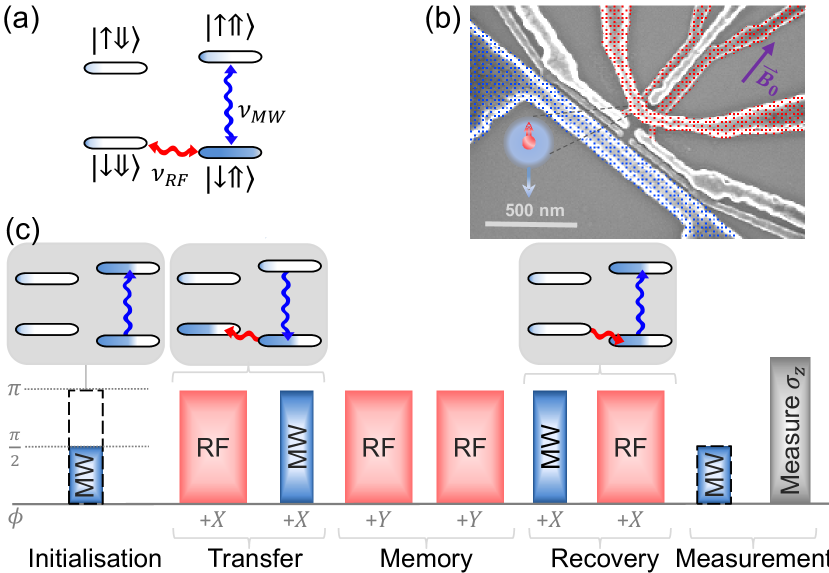
The donor qubit system and supporting nanoelectronics are illustrated in Figure 1(b), which shows a scanning electron micrograph of a device from the same batch as that measured. A single electron transistor (SET), defined electrostatically by aluminium gates on top of a SiO2 insulating layer, is shown in red. Control gates to tune the electrochemical potential of the donor are shown uncoloured, while the broadband microwave antenna [34] used for spin resonance [7, 10] is shown in blue. The location of the donor atom is indicated by the inset schematic. The device was fabricated on a 900 nm thick epilayer of isotopically enriched 28Si [11, 13], with phosphorus donor atoms implanted [35] into the epilayer in a small nm2 window prior to the fabrication of the aluminium nanostructures used for readout and control. The chip was bonded to a high-frequency printed circuit board, mounted in a copper enclosure, and thermalised to the mixing chamber of a dilution refrigerator with electron temperature mK. All experiments were performed in a static magnetic field T, oriented in the plane of the silicon chip along the [110] crystallographic direction.
The Hamiltonian of the system, in frequency units, is , where and are the vector Pauli matrices describing the electron and the nuclear spin, respectively, MHz is the electron-nuclear hyperfine interaction for this particular donor [19] and is the static magnetic field which defines the -direction. For T, the eigenstates are almost exactly the tensor product combinations of electron () and nuclear () states, as illustrated in the sketch in Figure 1(a). The hyperfine interaction introduces a coupling between the and states, which becomes negligible in the limit relevant to the present experiment [36]. The electron qubit is operated at a microwave frequency GHz when the nucleus is in the state, while the nuclear spin is operated at radio frequency MHz when the electron state is .
2.1 Qubit measurement and initialisation
The measurement observable in our system is the expectation value of the -component of the electron spin . The physical process that gives access to the quantum state of the electron is the energy-dependent tunnelling [37] of the donor-bound electron into the island of the SET [38, 39]. The large Zeeman splitting between the and states ensures that only an electron in the state can escape the donor, leaving behind a positive charge that shifts the SET bias point and resulting in a current spike detectable in single-shot [39]. This provides both readout of the electron spin state and initialisation into a state, since only an electron in the can tunnel back to the donor. Nuclear initialisation in the state is achieved with a sequence of MW and RF -pulses [18]. Starting from the electron state and the nuclear spin in an unknown state, the MW -pulse flips the electron to only if the nucleus is . In that case, the subsequent RF -pulse is off-resonance with the nucleus and leaves it in the target . Conversely, if the nucleus is initially , the MW pulse is off-resonance with the electron, and the subsequent RF pulse flips the nucleus from to . With one more electron readout/initialization step, the system is unconditionally prepared in the electron-nuclear eigenstate before the start of the quantum memory protocol.
2.2 Pulse sequences and state tomography
The memory storage and retrieval process is illustrated in Figure 1(c). ‘Initialisation’ describes the preparation of an arbitrary electron state with a microwave pulse of variable length and phase. ‘Transfer’ and ‘recovery’ of this state between electron and nuclear coherences is achieved via the electron-nuclear double resonance (ENDOR) technique [25]. In the ‘transfer’ stage, the first RF pulse conditionally shifts the component of the electron spin state onto the component of the nucleus, creating a double quantum coherence between and if the electron possessed a component. The subsequent MW -pulse conditional on the nuclear subspace, translates the component onto the state, leaving the nuclear spin with all the quantum information and the electron spin in the eigenstate. The ‘transfer’ operation of the memory protocol is now complete and the quantum information may be left in the nuclear state for the desired wait time before reversing the order of ENDOR pulses (‘recovery’ sequence) to bring the quantum information back to the electron state.
For the phase of the RF and MW pulses, we adopt a labelling convention where a pulse at produces a state if the spin started in the state. During the storage phase we apply, at a minimum, two nuclear -pulses to provide some degree of dynamical decoupling from environmental noise. The phase of these pulses is set at relative to the phase of the RF transfer pulse. This constitutes a Carr-Purcell-Meiboom-Gill (CPMG) sequence for input states along , or a Carr-Purcell (CP) for input states along . Following the recovery pulses, the state of the quantum memory is brought back to the electron spin (third inset). A final MW pulse is optionally added to change the electron spin measurement basis.
State tomography of a single qubit requires at least three measurement bases [40]. The component is the natural measurement basis in our setup, whereas readout of spin components orthogonal to is achieved by applying rotations about axes in the plane (final pulse in Figure 1(c)), mapping the desired readout basis to the observable. We used 24 measurement bases along the plane, applying a MW pulse of varying phase, , prior to -readout.
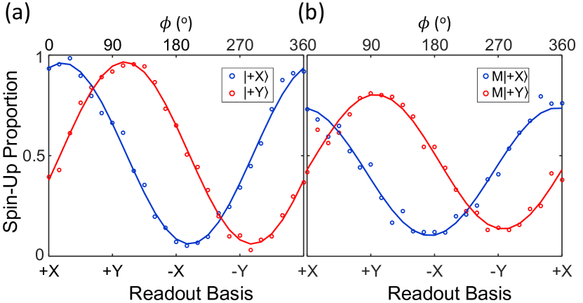
Figure 2(a) and (b) shows the ‘ tomography’ before and after 196 s of memory storage (1 s of free precession and two 97.4 s nuclear DD pulses), following the sequence shown in Figure 1(c). Results are shown for an initial state in blue and in red. The readout bases correspond to , , and for = 0, 90, 180 and 270∘, respectively. Figure 2(a) shows tomography on the initialised input states, in a sequence consisting only of the ‘initialisation’ and ‘measurement’ stages shown in Figure 1(c). Figure 2(b) shows tomography on the final electron state following the full memory sequence, with 196 s storage time. A sinusoidal fit of the results for each input reveals a maximum signal in a basis approximately aligned with the input superposition, as expected. A small phase shift is noticeable, and is caused by a detuning of order 10 kHz between the electron qubit and the frequency of the MW drive (see Pulse-induced resonance shift). Rather than directly using the and results, the amplitude and phase of this sinusoidal fit are used to calculate and for tomography. This tomography method was designed to minimise errors due to any measurement bias in the tomographic bases chosen.
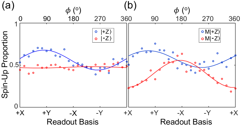
Figure 3 displays the plane tomography results for and states following initialisation (a) and full 196 s memory sequence (b). An ideal memory process should produce a horizontal line at 0.5. The oscillations observed in the -plane for these nominally -states indicate the presence of detectable or components. These oscillations are due to anomalous time-dependent shifts in the electron spin resonance after the application of an RF pulse, as described below (see Pulse-induced resonance shift). Selecting a single frequency for the sequence forced a compromise between the tuning of the initialisation MW pulse and that of the pulses in the subsequent memory sequence, leaving both slightly detuned from the instantaneous electron resonance frequency. As a result, the initialized states (nominally or ) contain spurious and components. However, the initialisation errors can be deconvoluted from the total errors to obtain a ‘memory fidelity’, which represents the fidelity of the storage/retrieval process relative to the actual initialised inputs.
The amplitude of the oscillations in Figure 2 is limited by any non-zero -component of the state as well as by the maximum visibility of the readout. The and -components ( and ) of the spin were calculated from the amplitude and phase of the curve, with errors determined by the fit. Tomography for the -component, , is performed separately without change of basis. Using 200 shots per point, the results were averaged over 25 repetitions, with error calculated as the standard deviation of the total distribution.
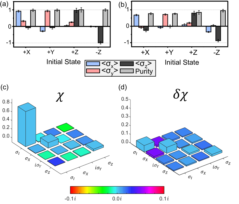
Figure 4(a,b) shows the analysis of the state tomography results for the initialised states (a) and output states (b) of the memory process, using four input states (, , and ) that span the qubit space [40]. The state purity, defined as , is also shown. Comparing the fidelity of the output state with that of the ideal input gives useful information about errors in the storage/retrieval process[27], while comparing the input states with the ideal inputs shows errors in state preparation and measurement (SPAM). For a measured state and ideal state , the state fidelity is defined as . Table 1 shows the state fidelities for each stored state as well as the fidelity of the initialisation. Averaging over the four stored states gives mean state fidelities % and % for the initialisation and overall process, respectively. Deconvoluting the SPAM errors in the initialisation and read-out from errors in the memory itself implies an average state fidelity % for the memory storage and retrieval itself, comparable with the value obtained in ensemble experiments [25].
| State | +X | +Y | +Z | -Z | Mean |
|---|---|---|---|---|---|
| (%) | 96 3 | 97 3 | 99 6 | 100 4 | 98 9 |
| (%) | 84 3 | 86 3 | 89 6 | 94 4 | 89 8 |
| (%) | 87 4 | 89 4 | 91 6 | 94 4 | 91 12 |
2.3 Process tomography
The storage process was further characterised with quantum process tomography [40], using the state tomography results on the four basis states. Assuming process linearity, the behaviour of the applied process on these basis states can be characterised as a linear combination of Pauli operators = , , , . For an input state , the process is represented as . The matrix is called the process matrix and its diagonal elements represent the fidelity of the process relative to the corresponding Pauli operator .
The process matrix for a 196 storage protocol is depicted in Figure 4(c), where the height of each column represents the real part of the matrix element and the imaginary part is described by the colour. Similarly, Figure 4(d) shows the uncertainty in these matrix elements as calculated via maximum likelihood estimation and Monte Carlo analysis [30]. The process is dominated by the identity operation, as required for a quantum memory. The matrix element corresponding to row and column indicates a process fidelity %. Imaginary and negative components of the matrix are minimal, as expected, and the largest error is a % -like component. Process tomography on the initialised inputs reveals an initialisation fidelity %, with a 7% -like error. Adjusting the process fidelity for this initialisation error gives an estimated fidelity for the memory process itself %, comparable to the value obtained with defects in diamond [29, 30]. The remaining errors are largely due to a systematic shift in the instantaneous ESR frequency induced by application of RF pulses, causing errors in rotation angle and phase during both the initialisation and the memory sequences (see Pulse-induced resonance shift below).
Estimating the errors in the process matrix elements requires repeated applications of the maximum likelihood procedure to multiple sets of tomographic data with real or simulated errors, as described e.g. in Refs. [30, 41]. Gaussian noise was added to the density matrix elements based on the measurement uncertainties, simulating output states within the error bars of the measurement. For each simulation, a process matrix is generated that has the maximum likelihood of producing these outputs via least squares minimisation. An extra constraint is added to maximise the hermiticity and positivity of each [30]. A Monte Carlo distribution of 20,000 process matrices and sets of state fidelities were generated. The standard deviations in the set of 20,000 results were used to estimate the error in the calculated fidelities.
2.4 Pulse-induced resonance shift
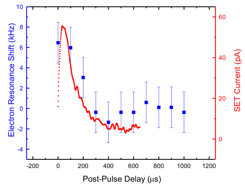
The power of the RF pulses applied during the transfer and recovery stages of the memory sequence needs to be high enough to ensure that the transfer time is short compared to the electron dephasing time ( s) [11]. In the present experiment, we used typical RF powers of dBm at the source, which corresponds to approximately dBm at the sample. Following the application of these high-power RF pulses it was found that the electron spin resonance frequency exhibits a transient shift, as shown in Figure 5. The peak frequency detuning is typically kHz and lasts on the order of 200 s. Plotting on the same graph the time dependence of (blue) and of the SET current (red) following an RF pulse shows that the two are correlated. However, we found no causal link between the SET current and the frequency detuning, i.e. deliberately running a current through the SET does not shift . In this test, the RF pulse was tuned completely off-resonance and any frequency dependence of the effect was negligible over the MHz range of the RF source used. The shift was found to be positive for both ESR frequencies (data not shown), implying an effective shift in the Zeeman term of the Hamiltonian, rather than in the hyperfine coupling. The physical origin of this resonance shift is currently unknown.
In the present experiment, this pulse-induced resonance shift results in a different instantaneous electron resonance frequency during the ‘initialization’ MW pulse (which precedes any RF pulse) and during the ENDOR sequences, preventing us from achieving perfect initialization and/or state transfer. In the practice, we chose a compromise where the MW source is slightly detuned from the instantaneous electron resonance under both conditions. We anticipate that improved memory fidelities will be achieved once the pulse-induced resonance shift is understood and mitigated.
2.5 Memory lifetime
As a result of the long coherence time of the nuclear spin, the process fidelity decays slowly with storage time. For instance we measure % after 10 ms, corresponding to a memory fidelity %. High-fidelity storage can be extended to longer times by dynamically decoupling the nuclear spin. Figure 6(a) shows the probability of recovering an initial -state as a function of storage time, for different numbers of DD pulses applied to the nucleus during storage. This can be thought of as the CPMG coherence time, of the memory storage process. Figure 6(b) compares this memory (black) to nuclear CPMG coherence times (red) with varying number of applied CPMG pulses. Both values approach 80 ms for pulses, with the memory following a similar trend to that of the neutral nucleus. Electron CPMG coherence times, shown in blue, are shorter than the nuclear and memory times for small , but tend to approach them for higher number of CPMG pulses. The values of as a function of show increase in proportion to , and for the electron, nucleus and memory, respectively.
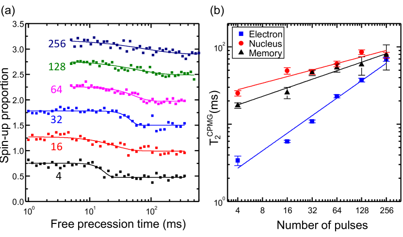
The different trend of between electron, nucleus and memory as a function of is not fully understood, but is suspected to be related to the pulse-induced resonance shift described above. We note indeed that the neutral nucleus coherence times reported here are much longer than those measured in an earlier experiment on the same device [11], where even higher RF powers were used. This suggests that there might be a pulse-induced resonance shift on the nuclear spin as well – too small to be detected directly in a Ramsey experiment as we managed to do for the electron (Figure 5), but large enough to perturb the coherent evolution of the nuclear spin. While this can be mitigated to some extent by reducing the RF power, the memory protocol requires nuclear -pulses shorter than the electron dephasing time s [11] for faithful transfer of the electron state to the nucleus. We found the best results by choosing memory transfer RF -pulses of duration 50 s, and lower-power -pulses (97 s) applied for DD during the storage phase.
3 Conclusion
In conclusion, we have experimentally demonstrated a nuclear spin quantum memory using a single P atom in silicon. The memory coherence time (up to 80 ms) and the memory process fidelity (better than 90%) are comparable to those found in nitrogen-vacancy centres in diamond [29, 30], trapped ions [27] and P-atom ensembles [25]. We have identified a likely cause of the coherence and fidelity limitations, namely a shift in the instantaneous electron resonance frequency after applying RF pulses. Future work will focus on understanding and eliminating this pulse-induced frequency shift, in order to demonstrate quantum memory fidelities approaching the values of gate fidelity (%) [42, 43] already observed for the operation of the electron and nuclear spin qubits individually.
Acknowledgements
This research was funded by the Australian Research Council Centre of Excellence for Quantum Computation and Communication Technology (project number CE11E0001027), the US Army Research Office (W911NF-13-1-0024) and the Commonwealth Bank of Australia. We acknowledge support from the Australian National Fabrication Facility, and from the laboratory of Prof Robert Elliman at the Australian National University for the ion implantation facilities. The work at Keio has been supported in part by KAKENHI (S) No. 26220602, Core-to-Core Program by JSPS, and Spintronics Research Network of Japan.
References
References
- [1] Wootters W K and Zurek W H 1982 Nature 299 802–803
- [2] Simon C, Afzelius M, Appel J, de La Giroday A B, Dewhurst S, Gisin N, Hu C, Jelezko F, Kröll S, Müller J et al. 2010 The European Physical Journal D 58 1–22
- [3] Julsgaard B, Sherson J, Cirac J I, Fiurášek J and Polzik E S 2004 Nature 432 482–486
- [4] Wilk T, Webster S C, Kuhn A and Rempe G 2007 Science 317 488–490
- [5] Lvovsky A I, Sanders B C and Tittel W 2009 Nature Photonics 3 706–714
- [6] Hedges M P, Longdell J J, Li Y and Sellars M J 2010 465 1052–1056
- [7] Pla J J, Tan K Y, Dehollain J P, Lim W H, Morton J J L, Jamieson D N, Dzurak A S and Morello A 2012 Nature 489 541–545
- [8] Steger M, Saeedi K, Thewalt M L W, Morton J J L, Riemann H, Abrosimov N V, Becker P and Pohl H J 2012 Science 336 1280–1283
- [9] Saeedi K, Simmons S, Salvail J Z, Dluhy P, Riemann H, Abrosimov N V, Becker P, Pohl H J, Morton J J L and Thewalt M L W 2013 Science 342 830–833
- [10] Pla J J, Tan K Y, Dehollain J P, Lim W H, Morton J J L, Zwanenburg F A, Jamieson D N, Dzurak A S and Morello A 2013 Nature 496 334–338
- [11] Muhonen J T, Dehollain J P, Laucht A, Hudson F E, Sekiguchi T, Itoh K M, Jamieson D N, McCallum J C, Dzurak A S and Morello A 2014 Nature Nanotechnology 9 986–991
- [12] Witzel W M, Carroll M S, Morello A, Cywiński Ł and Sarma S D 2010 Physical Review Letters 105 187602
- [13] Itoh K M and Watanabe H 2014 MRS Communications 4 143–157
- [14] Dupont-Ferrier E, Roche B, Voisin B, Jehl X, Wacquez R, Vinet M, Sanquer M and De Franceschi S 2013 Physical Review Letters 110 136802
- [15] Dehollain J P, Muhonen J T, Tan K Y, Saraiva A, Jamieson D N, Dzurak A S and Morello A 2014 Physical Review Letters 112 236801
- [16] Gonzalez-Zalba M F, Saraiva A, Calderón M J, Heiss D, Koiller B and Ferguson A J 2014 Nano Letters 14 5672–5676
- [17] Weber B, Tan Y, Mahapatra S, Watson T F, Ryu H, Rahman R, Hollenberg L C, Klimeck G and Simmons M Y 2014 Nature Nanotechnology 430–435
- [18] Dehollain J P, Simmons S, Muhonen J T, Kalra R, Laucht A, Hudson F, Itoh K M, Jamieson D N, McCallum J C, Dzurak A S et al. 2016 Nature Nanotechnology 11 242–246
- [19] Laucht A, Muhonen J T, Mohiyaddin F A, Kalra R, Dehollain J P, Freer S, Hudson F E, Veldhorst M, Rahman R, Klimeck G et al. 2015 Science Advances 1 e1500022
- [20] Harvey-Collard P, Jacobson N T, Rudolph M, Dominguez J, Eyck G A T, Wendt J R, Pluym T, Gamble J K, Lilly M P, Pioro-Ladrière M et al. 2015 arXiv preprint arXiv:1512.01606
- [21] Urdampilleta M, Chatterjee A, Lo C C, Kobayashi T, Mansir J, Barraud S, Betz A C, Rogge S, Gonzalez-Zalba M F and Morton J J 2015 Physical Review X 5 031024
- [22] Tosi G, Mohiyaddin F A, Tenberg S B, Rahman R, Klimeck G and Morello A 2015 arXiv preprint arXiv:1509.08538
- [23] Hill C D, Peretz E, Hile S J, House M G, Fuechsle M, Rogge S, Simmons M Y and Hollenberg L C L 2015 Science Advances 1 e1500707
- [24] McCamey D R, Van Tol J, Morley G W and Boehme C 2010 Science 330 1652–1656
- [25] Morton J J L, Tyryshkin A M, Brown R M, Shankar S, Lovett B W, Ardavan A, Schenkel T, Haller E E, Ager J W and Lyon S A 2008 Nature 455 1085–1088
- [26] Kielpinski D, Meyer V, Rowe M A, Sackett C A, Itano W M, Monroe C and Wineland D J 2001 Science 291 1013–1015
- [27] Specht H P, Nölleke C, Reiserer A, Uphoff M, Figueroa E, Ritter S and Rempe G 2011 Nature 473 190–193
- [28] Dutt M G, Childress L, Jiang L, Togan E, Maze J, Jelezko F, Zibrov A, Hemmer P and Lukin M 2007 Science 316 1312–1316
- [29] Fuchs G, Burkard G, Klimov P and Awschalom D 2011 Nature Physics 7 789–793
- [30] Maurer P C, Kucsko G, Latta C, Jiang L, Yao N Y, Bennett S D, Pastawski F, Hunger D, Chisholm N, Markham M et al. 2012 Science 336 1283–1286
- [31] Shim J H, Niemeyer I, Zhang J and Suter D 2013 Physical Review A 87 012301
- [32] Reiserer A, Kalb N, Blok M S, van Bemmelen K J M, Taminiau T H, Hanson R, Twitchen D J and Markham M 2016 Phys. Rev. X 6(2) 021040
- [33] Massar S and Popescu S 1995 Physical Review Letters 74 1259–1263
- [34] Dehollain J P, Pla J J, Siew E, Tan K Y, Dzurak A S and Morello A 2013 Nanotechnology 24 015202
- [35] van Donkelaar J, Yang C, Alves A, McCallum J, Hougaard C, Johnson B, Hudson F, Dzurak A, Morello A, Spemann D et al. 2015 Journal of Physics: Condensed Matter 27 154204
- [36] Kalra R, Laucht A, Hill C D and Morello A 2014 Phys. Rev. X 4(2) 021044
- [37] Elzerman J, Hanson R, Van Beveren L W, Witkamp B, Vandersypen L and Kouwenhoven L P 2004 Nature 430 431–435
- [38] Morello A, Escott C, Huebl H, van Beveren L W, Hollenberg L, Jamieson D, Dzurak A and Clark R 2009 Physical Review B 80 081307
- [39] Morello A, Pla J J, Zwanenburg F A, Chan K W, Tan K Y, Huebl H, Mottonen M, Nugroho C D, Yang C, van Donkelaar J A, Alves A D C, Jamieson D N, Escott C C, Hollenberg L C L, Clark R G and Dzurak A S 2010 Nature 467 687–691
- [40] Nielsen M and Chuang I 2010 Quantum computation and quantum information 10th ed (New York: Cambridge University Press)
- [41] O’Brien J L, Pryde G J, Gilchrist A, James D F V, Langford N K, Ralph T C and White A G 2004 Phys. Rev. Lett. 93(8) 080502
- [42] Muhonen J, Laucht A, Simmons S, Dehollain J, Kalra R, Hudson F, Freer S, Itoh K M, Jamieson D, McCallum J et al. 2015 Journal of Physics: Condensed Matter 27 154205
- [43] Dehollain J P, Muhonen J T, Blume-Kohout R, Rudinger K M, Gamble J K, Nielsen E, Laucht A, Simmons S, Kalra R, Dzurak A S and Morello A 2016 arXiv preprint arXiv:1606.02856