† These authors contributed equally to this work.
Coupling ideality of integrated planar high-Q microresonators
Abstract
Chipscale microresonators with integrated planar optical waveguides are useful building blocks for linear, nonlinear and quantum optical devices. Loss reduction through improving fabrication processes has resulted in several integrated microresonator platforms attaining quality (Q) factors of several millions. However only few studies have investigated design-dependent losses, especially with regard to the resonator coupling section. Here we investigate design-dependent parasitic losses, described by the coupling ideality, of the commonly employed microresonator design consisting of a microring resonator waveguide side-coupled to a straight bus waveguide. By systematic characterization of multi-mode high-Q silicon nitride microresonator devices, we show that this design can suffer from low coupling ideality. By performing full 3D simulations to numerically investigate the resonator to bus waveguide coupling, we identify the coupling to higher-order bus waveguide modes as the dominant origin of parasitic losses which lead to the low coupling ideality. Using suitably designed bus waveguides, parasitic losses are mitigated, and a nearly unity ideality and strong overcoupling (i.e. a ratio of external coupling to internal resonator loss rate ) are demonstrated. Moreover we find that different resonator modes can exchange power through the coupler, which therefore constitutes a mechanism that induces modal coupling, a phenomenon known to distort resonator dispersion properties. Our results demonstrate the potential for significant performance improvements of integrated planar microresonators, achievable by optimized coupler designs.
I Introduction
Microresonator devices are ubiquitously used in integrated photonic circuits and enable applications that range from passive elements such as filters (Little1997, ) and sensors (DeVos2007, ), over active components such as modulators (Reed2005, ), to nonlinear applications (Leuthold2010, ; Moss2013, ) such as wavelength conversion (Li2015, ) and Kerr frequency comb generation (Kippenberg2011, ). While most microresonator devices in silicon photonics are formed by single-mode waveguides (Jalali2006, ; Nagarajan2005, ), many recent photonic integrated circuits rely on multi-mode waveguides due to their lower losses (Cherchi2013, ; Bauters2011, ), higher data capacity (Luo2014, ), improved device integration (Wade2014, ) and tailored dispersion properties e.g. to attain anomalous group velocity dispersion required for parametric frequency conversion (Turner2006, ; Riemensberger2012, ). Early research on ultra high-Q microresonators in other platforms led to the development of several adjustable evanescent coupling techniques based on prisms and tapered optical fibers (Braginsky1989, ; Knight1997, ; Gorodetsky1999, ; Cai2000, ; Spillane2003, ). To quantitatively describe the performance of these couplers , the “coupling ideality” was defined for tapered fiber coupling to microspheres, as the ratio of the power coupled from the resonator to the fundamental fiber mode divided by the total power coupled to all guided and non-guided fiber modes (Spillane2003, ). In this case parasitic losses degrading coupling ideality can be present if the tapered fiber is multi-mode.
In the context of integrated planar microresonator devices, design rules (Soltani2007, ; Hosseini2010, ) and optimized coupler geometries (Ghulinyan2013, ; Pencer2014, ; Wade2014, ) have been reported. However, comparatively little attention has been paid to the coupler performance, especially with regard to the multi-mode nature of waveguides. Only few reports of coupler-induced excess losses (Fengnian2006, ; Li2016, ) have been published and most integrated microresonator devices, single- or multi-mode, rely on the coupler design consisting of a simple side-coupled straight bus waveguide with a cross section identical to the resonator waveguide.
Here we present a comprehensive investigation of integrated planar high-Q silicon nitride () microresonator devices with several different coupler designs. Experimental resonance characterization with sufficiently large statistics and full 3D numerical simulations allow us to unambiguously reveal the detrimental effect of non-ideal coupler designs, even in the presence of statistical fluctuations of resonator properties due to fabrication variations. The commonly employed coupler design using a bus waveguide of the same cross section as the resonator is found to exhibit parasitic losses due to the modal coupling to higher-order bus waveguide modes, which can severely limit the device performance. In contrast, for the design of a multi-mode resonator coupled to a single-mode bus waveguide, we observe nearly ideal coupler performance. Finally, our simulations show that coupling between different resonator modes can originate from the coupler. This provides a novel insight into the origin of modal coupling in microresonators observed in previous work (Herr2014, ; Braschaad4811, ), which leads to distortion of resonator dispersion properties.
II Analytical description of a multi-mode coupling section
Typically the evanescent coupling of light to a microresonator is described using coupled-mode theory as a power transfer to a resonator mode at the rate (Gorodetsky1999, ; Cai2000, ; haus1984waves, ). Treating the resonator in a lumped model (Rowland1993, ; Yariv2000, ), the coupling rate is typically estimated using the model of coupling between two co-propagating modes in adjacent waveguides (Yariv1973, ). In contrast to the power coupling ratios of conventional directional couplers, the high-Q microresonator’s low internal loss rate requires only minute power transfer to achieve critical coupling (i.e. ) for which the intra-cavity power build-up is maximal. Thus the coupled modes in both the resonator and the bus waveguides can be essentially treated as independent, and depends on the mutual modal overlap and propagation constant mismatch (i.e. phase mismatch) (Little1997, ; Gorodetsky1999, ; Yariv1973, ). This model is widely applied as it provides a qualitative insight for most cases where coupling between only two modes is considered, neglecting the coupling to other modes.
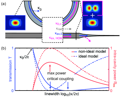
In practice for high-Q microresonators, a commonly employed coupler design consists of a side-coupled, straight bus waveguide identical in cross section to the resonator waveguide. The cross section is chosen in order to match the propagation constants of e.g. the fundamental resonator and bus waveguide modes. However in the case of multi-mode waveguides, as found for tapered fiber coupling to microspheres (Spillane2003, ), coupling between different modes has to be considered as depicted in Fig. 1(a). Moreover, the coupler can scatter light into free space modes and recently was also identified to couple the counter-propagating, clockwise (CW) and counter-clockwise (CCW) waveguide modes (Li2016, ), which is not considered in the present work. As a result the corresponding equation of motion for the resonator modal amplitude of frequency in the rotating frame of the driving laser has to be extended to:
| (1) |
Here and are the frequency detunings between the driving laser with amplitude and the resonator modes and . The intra-cavity field decays due to the internal loss rate and the external coupling rate to the fundamental bus waveguide mode. The radiations into free space modes with the rate and to higher-order bus waveguide modes with the rate form the parasitic coupling rate , which accelerates the intra-cavity field decay.
In addition, the modal coupling term is introduced to account for the fact that the resonator mode can couple to other modes with the rate . Such modal coupling is usually considered to arise from surface roughness, but is later found to originate also from the coupler. This term is only relevant if the coupled modes are simultaneously resonant. Such modal coupling causes deviations of the resonance frequencies, so called “avoided modal crossings”, that locally distort resonator dispersion. As the modal coupling term contributes to the parasitic coupling rate only at such modal crossing points, it is not included in . The coupling ideality of the resonator mode , describing the relative strength of parasitic coupling rates, is defined according to Ref. (Spillane2003, ) as:
| (2) |
In the following the effects of coupling ideality on device performance are considered. While the scattering of light into free space modes directly represents a power loss, the power coupled to higher-order modes of the bus waveguide is not necessarily lost. However in most cases the higher-order bus waveguide modes are filtered out e.g. by inverse taper mode converters (Almeida2003, ). Thus the measured transmitted power at the device facets only consists of the power of the bus waveguide’s fundamental mode, and the input-output relation holds with representing a parasitic loss which enlarges the resonance linewidth. On resonance , the device power transmission and intra-cavity power as function of the coupling ideality and coupling parameter are expressed as:
| (3) |
| (4) |
Here is the resonator free spectral range (FSR). Assuming an input power and a constant , Fig. 1(b) plots both the power transmission and intra-cavity power as function of the total linewidth for the ideal () and non-ideal () case, with a constant and varying . The effects of the non-ideal coupling become apparent: in the case of the ideal coupling (dashed lines), the point of the full power extinction (i.e. , the critical coupling point) coincides with the point of the maximum intra-cavity power. This is different for the non-ideal case (solid lines), in which the parasitic losses increase linearly with the coupling rate . More importantly the maximum value of the intra-cavity power is reduced compared to the ideal case. Due to the parasitic losses, critical coupling and overcoupling are only achieved at larger total linewidth, or can not be achieved at all if . It is therefore evident that in applications exploiting the resonator’s power enhancement e.g. nonlinear photonics, device performance will improve with higher coupling ideality. Likewise, the analysis shows that linewidth measurements carried out near the critical coupling point include possible parasitic losses, preventing faithful measurements of the intrinsic quality factor.
III Experimental study of coupling ideality
We experimentally study the coupling ideality for integrated microresonators, a widely employed platform for on-chip nonlinear photonics such as Kerr frequency comb generation (Kippenberg2011, ) and soliton formation (Herr2013a, ). For microresonator platforms with adjustable couplers e.g. tapered fibers and prism couplers, changing the evanescent coupling rates allows to measure the transmission-linewidth dependence of a single resonance (Spillane2003, ; Gorodetsky1999, ) and to retrieve the coupling ideality via Eq. 3. In contrast, here we study photonic chips with several microresonator devices that consist of resonator and bus waveguides, as well as inverse taper mode converters (Almeida2003, ) placed at the chip facets. The microresonator devices on each chip are identical but have varying resonator-bus distances providing different coupling rates. In this case, coupling ideality is evaluated by analyzing the transmission-linewidth dependence of many resonances acquired for each microresonator device. By using a statistically large number of devices we overcome the variations in quality factor Q inherent to the fabrication process itself.
The waveguide core is made from silicon nitride () and fully cladded with silicon dioxide (). All measured chips were fabricated on the same wafer using a photonic Damascene process (Pfeiffer2016, ). In contrast to typical subtractive processes, this process allows for void-free, high-aspect-ratio coupler gap fabrication, eliminating excess losses due to the presence of voids. By using lensed fibers, light is coupled efficiently (loss per facet) into a single fundamental mode of the bus waveguide. Calibrated power transmission traces are acquired for all devices on the chip from 1500 nm to 1630 nm with a similar method as described in Ref. (DelHaye2009, ). A polarization controller is used to select and maintain a stable input polarization over the full measurement bandwidth. Resonances in each recorded device transmission trace are automatically identified and fitted using a model of a splitted Lorentzian lineshape (Gorodetsky2000, ). The resonances are grouped into different mode families by measuring their mutual FSRs and comparing them to finite-element simulations of the device geometry.
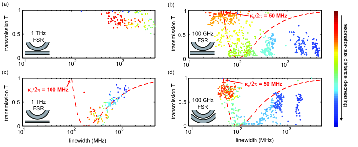
Fig. 2 compares the measured transmission-linewidth dependence of the resonator’s transverse magnetic fundamental mode families () for two 1 THz FSR (Panels a, c) and two 100 GHz FSR (Panels b, d) microresonator device chips. The cross section of the resonator waveguide is height, and (100 GHz FSR) and (1 THz FSR) width respectively. Each point represents a measured resonance, and points with the same color are from the same microresonator device. Different colors denote different resonator-bus distances. The red dashed line traces out the transmission-linewidth dependence for the ideal coupling of unity ideality with a fixed internal loss .
Fig. 2(a) shows an example of low coupling ideality: a small radius ( ), 1 THz FSR resonator coupled to a multi-mode bus waveguide of the same cross section. The measured resonances of the fundamental mode family have GHz linewidth and low extinction (i.e. high transmission), and their measured transmission-linewidth dependence does not follow a clear trend. Due to the identical cross sections of the resonator and the bus waveguides, this coupler design could be naively assumed to provide good propagation constant match between the resonator and bus waveguide TM fundamental modes, i.e. and . However due to the small ring radius, the propagation constants of the and modes are strongly mismatched, despite the identical waveguide cross sections.
As shown in Fig. 2(b), also a 100 GHz FSR resonator, with a ten times larger radius (), can have limited coupling ideality when interfaced with a straight bus waveguide of the same cross section. Although featuring resonance linewidths below MHz and an average linewidth of MHz, the microresonator can not be efficiently overcoupled, indicating the presence of parasitic losses.
Fig. 2(c) and (d) present two possible coupler designs that improve coupling ideality. First, as shown in Fig. 2(c) almost unity ideality and strong overcoupling are achieved for a 1 THz FSR microresonator coupled to a single-mode bus waveguide. The bus waveguide has a cross section of height and width due to the aspect-ratio-dependent etch rate during the preform etch (Pfeiffer2016, ). It can thus be concluded that the main source of parasitic losses leading to the low ideality in Fig. 2(a) originates from the coupling to higher-order bus waveguide modes. Therefore using a single-mode bus waveguide can essentially avoid this kind of parasitic losses and significantly improve coupling ideality to near unity. Also strong overcoupling can be achieved with an external coupling rate almost a magnitude larger than the internal losses (coupling parameter ).
However in most cases when using a single-mode bus waveguide, though coupling ideality is improved, the propagation constants of the bus and resonator fundamental modes (e.g. and ) are strongly mismatched which limits the maximum value of the coupling rate . Thus a narrow gap is needed to achieve sufficient modal overlap and a large enough coupling rate to achieve overcoupling. For the 1 THz FSR resonator, a coupling rate sufficient for overcoupling is achieved due to its small mode volume and low internal loss per round-trip (). However for smaller FSR resonators with larger mode volumes e.g. 100 GHz FSR, overcoupling might not be achieved in the case of strong propagation constant mismatch, as fabrication processes pose limitations on the narrowest resonator-bus distance. One alternative solution for smaller FSR, larger radius resonators to achieve efficient overcoupling is to use a pulley-style coupler (Hosseini2010, ). Fig. 2(d) shows the measurement results for a 100 GHz FSR microresonators coupled with a multi-mode bus waveguide of the same cross section but in the pulley-style configuration. The comparison between the two 100 GHz FSR resonators in Fig. 2(b) and Fig. 2(d) reveals an improved coupling ideality for the pulley-style coupler, which is however not as high as the case of the 1 THz FSR resonator coupled to a single-mode bus waveguide in Fig 2(c). However such a comparison neglects the large difference in resonator mode volume. In fact the fundamental mode of the present 100 GHz FSR resonator can not be overcoupled using a single-mode bus waveguide, as the strong propagation constant mismatch limits the achievable coupling rates .
IV Simulations of coupling ideality
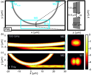
In order to verify the dominant origin of parasitic losses and the observed strong design-dependence of coupling ideality, we implement a full 3D finite-difference-time-domain (FDTD) (Taflove2005, ) simulation (Lumerical FDTD). This allows to study numerically the light propagation through the coupler by solving Maxwell’s equations in the time domain. The simulation model is shown in Fig. 3(a). Considering the designs of the microresonator devices experimentally characterized in the previous section, the resonator and the bus waveguide have the same cross sections, which is (widthheight) for the 1 THz FSR resonator and for the 100 GHz FSR resonator. The sidewall angle is and the resonator-bus distance is set as . A graded mesh of rectangular cells with the maximum cell volume of nm is applied to the simulation region. The boundary condition enclosing the full simulation region is set as perfectly matched layer (PML) (Berenger, ), to absorb the incident light to the boundary and thus to prevent back-reflection.
The resonator fundamental mode at the center wavelength of 1550 nm is launched with unity power and the light field propagates until the field distribution reaches the stationary state in the full simulation region. Monitors M0, M1 and M2 record the field distributions in their individual monitor planes. Fig. 3(b) and (c) show the field distributions recorded by M0 and M1 for the resonators of 100 GHz and 1 THz FSR, respectively. An interference pattern in the field distribution along the bus waveguide is observed in both cases, and is more prominent in the case of 1 THz FSR. The field distributions recorded by M1 show that: (1) in the case of 100 GHz FSR, the field propagates predominantly in the bus waveguide fundamental mode, which indicates a limited, non-unity coupling ideality; (2) while in the case of 1 THz FSR, a significant portion of power is coupled to the higher-order mode that beats with the mode along the propagation in the bus waveguide, which indicates a lower coupling ideality. These qualitative conclusions from Fig. 3 agree well with the experimental observation that the 1 THz FSR resonator in Fig. 2(a) shows higher parasitic losses thus a lower coupling ideality compared to the 100 GHz FSR resonator in Fig. 2(b).
| No. | 1 | 2 | 3 | 4 | 5 | 6 | 7 |
| FSR | 1 THz | 1 THz | 1 THz | 1 THz | 1 THz | 100 GHz | 100 GHz |
| () | |||||||
| () | - | (SM) | |||||
| gap () | - | ||||||
| - | 0.0344 | 0.0237 | |||||
| - | 0.0176 | 0.0974 | 0.0173 | - | |||
| - | |||||||
| - | 0.0209 | 0.133 | 0.0203 | 0.0237 | |||
| - | 0.161 | 0.259 | 0.163 | 1.00 | 1.00 | 0.968 |
We perform further analysis to quantify the degradation of coupling ideality in the 1 THz FSR resonators. The total power coupled into the bus waveguide can be obtained by calculating the Poynting vector normal to the monitor plane of M1. In addition, using the "Mode Expansion Function" (MEF) of Lumerical FDTD, the field distribution recorded by M1 can be projected on each waveguide eigenmode and their individual power () can be calculated. All powers are normalized as they derive from the resonator fundamental mode that is launched with unity power. The respective coupling rate follows by relating the coupled power to the resonator FSR () by . The fundamental bus waveguide mode’s power can be obtained and the coupling ideality can thus be approximately estimated as , assuming that the coupling to the higher-order bus waveguide modes () is the dominant origin of parasitic losses. In addition, in order to investigate how the resonator mode is affected by the coupler, also the field distribution recorded by M2 in the resonator waveguide after the coupling section is decomposed into individual resonator modes using MEF.
Table 1 compiles the simulation results of different coupler designs (No. 1-7) with varying geometrical parameters, including the resonator FSR (radius), the cross sections of the resonator and the bus waveguides, the gap distance, and the waveguide sidewall angle . This angle takes into account the fact that the fabricated waveguides have slanted sidewalls (). For each design we calculate the individual power of the selected eigenmodes in the resonator ( and transverse electric fundamental resonator mode ) and the bus waveguide ( , and ), and numerically compute the coupling ideality .
First, Table 1 shows that the commonly employed coupler design of a straight bus waveguide coupling to a resonator waveguide of the same cross section, has a higher coupling ideality for the 100 GHz FSR resonators (No. 7, ) than for the 1 THz FSR resonators (No. 2, ). This agrees well with the previously discussed observations in Fig. 2 and Fig. 3. The degraded ideality in the case of 1 THz FSR resonators illustrates the limited applicability of this coupler design. The fact that the resonator radius strongly affects coupling ideality is more directly seen by comparing the cases No. 2 and 6, as both cases have exactly the same geometrical parameters except for the resonator FSR.
In addition, the coupling ideality of 100 GHz FSR resonators (No. 6, 7) depends also on the waveguide width when coupled to a bus waveguide of the same cross section. The degradation of coupling ideality in the case No. 7 is due to more power coupled to the higher-order bus waveguide mode (), which can be explained with the smaller propagation constant mismatch between the fundamental resonator mode () and the higher order bus waveguide mode (). Additionally the wider waveguide cross section reduces the mutual modal overlap between the fundamental and modes and thus the power transfer . Furthermore, our simulations verify the experimentally observed improvement of coupling ideality for the 1 THz FSR resonator coupled to a single-mode bus waveguide (No. 5, ) . However this is achieved at the expense of reducing power transfer to the bus waveguide by nearly one order of magnitude, which is due to the propagation constant mismatch between the and modes.
Second, though only the fundamental mode is launched in the resonator, a non-zero power in a higher-order mode is recorded by M2. In addition, it is observed by comparing the uncoupled (No. 1) and coupled cases (No. 2, 3) that this power in the higher-order resonator mode power increases with decreasing gap distance. In the case of the uncoupled resonator (No. 1), the appearance of is mainly attributed to the mesh which acts as a nm surface roughness at the material interface. Such surface roughness is well known to lead to modal coupling e.g. the coupling between the resonator modes and . In addition, compared with the 100 GHz FSR resonator (No. 6, 7), this effect is more prominent in the 1 THz FSR resonator (No. 1). Nevertheless for the coupled resonators (No. 2, 3), the enhancement of with decreasing gap distance unambiguously reveals the existence of a coupler-induced modal coupling. This is an important finding revealing a novel origin of modal coupling (Herr2014, ) in microresonators, which causes distortion of microresonator dispersion properties.
Third, the coupling of the launched mode to the modes with the orthogonal polarization, i.e. in the resonator and in the bus waveguide, is observed in the case of slanted waveguide sidewalls (No. 4). Such a cross-polarization coupling occurs if the modal field distribution is asymmetric with respect to its center (Lui1998, ; Liu2011, ) and its strength depends on the degree of this asymmetry. In the simulated case, the asymmetry is introduced by the ring bending and the sidewall angle. However by comparing the cases No. 2 and 4, the sidewall angle only enhances significantly the power , while the powers of other modes as well as the coupling ideality remain almost the same.
V Conclusion
In summary we presented the first study of coupling ideality of monolithically integrated high-Q microresonator devices. For the commonly employed coupler design where both the resonator and the bus waveguides have the same cross sections, we revealed the presence of parasitic losses due to the coupling to higher-order bus waveguide modes. This degrades coupling ideality which is shown both through systematic experimental characterization of resonances and full 3D FDTD simulations. Consequently, an optimized coupler design using a single-mode bus waveguide with efficiently mitigated parasitic losses (ideality ) and achieved strong overcoupling () was demonstrated. Moreover we discovered that the coupler can induce modal coupling between different resonator modes which is frequently observed in high-Q microresonators.
For microresonator devices based on multi-mode waveguides, coupling ideality is non-trivial to analyze and strongly depends on coupler designs and target mode families. In applications, microresonator devices typically operate around the critical coupling point, thus high device performance requires optimized coupler designs with low parasitic losses and high coupling ideality. Our study not only reveals the design-dependent coupling ideality for integrated microresonator devices but also demonstrate the importance of anticipating coupling ideality in device design and the significant improvements it can unlock.
Acknowledgements
SiN microresonator samples were fabricated in the EPFL Center of MicroNanotechnology (CMi). This publication was supported by Contract HR0011-15-C-0055 from the Defense Advanced Research Projects Agency (DARPA), Defense Sciences Office (DSO) and the Swiss National Science Foundation. M.G. acknowledges support from the Hasler foundation and support from the ‘EPFL Fellows’ fellowship program co-funded by Marie Curie, FP7 Grant agreement No. 291771.
References
- [1] B. E. Little, S. T. Chu, H. A. Haus, J. Foresi, and J. Laine. Microring resonator channel dropping filters. J. Lightwave Technol., 15(6):998–1005, 1997.
- [2] K. De Vos, I. Bartolozzi, E. Schacht, P. Bienstman, and R. Baets. Silicon-on-insulator microring resonator for sensitive and label-free biosensing. Opt. Express, 15(12):7610–7615, 2007.
- [3] G. T. Reed, G. Mashanovich, F. Y. Gardes, and D. J. Thomson. Silicon optical modulators. Nat. Photon., 4(8):518–526, 08 2010.
- [4] J. Leuthold, C. Koos, and W. Freude. Nonlinear silicon photonics. Nat. Photon., 4(8):535–544, 08 2010.
- [5] D. J. Moss, R. Morandotti, A. L. Gaeta, and M. Lipson. New CMOS-compatible platforms based on silicon nitride and hydex for nonlinear optics. Nat. Photon., 7(8):597–607, 2013.
- [6] Q. Li, M. Davanço, and K. Srinivasan. Efficient and low-noise single-photon-level frequency conversion interfaces using silicon nanophotonics. Nat. Photon., 10(6):406–414, 06 2016.
- [7] T. J. Kippenberg, R. Holzwarth, and S. A. Diddams. Microresonator-based optical frequency combs. Science, 332(6029):555–559, 2011.
- [8] B. Jalali and S. Fathpour. Silicon photonics. J. Lightwave Technol., 24(12):4600–4615, 2006.
- [9] R. Nagarajan, C. H. Joyner, R. P. Schneider, J. S. Bostak, T. Butrie, A. G. Dentai, V. G. Dominic, P. W. Evans, M. Kato, M. Kauffman, D. J. H. Lambert, S. K. Mathis, A. Mathur, R. H. Miles, M. L. Mitchell, M. J. Missey, S. Murthy, A. C. Nilsson, F. H. Peters, S. C. Pennypacker, J. L. Pleumeekers, R. A. Salvatore, R. K. Schlenker, R. B. Taylor, H.-S. Tsai, M. F. Van Leeuwen, J. Webjorn, M. Ziari, D. Perkins, J. Singh, S. G. Grubb, M. S. Reffle, D. G. Mehuys, F. A. Kish, and D. F. Welch. Large-scale photonic integrated circuits. IEEE J. Sel. Top. Quantum Electron., 11(1):50–65, 2005.
- [10] M. Cherchi, S. Ylinen, M. Harjanne, M. Kapulainen, and T. Aalto. Dramatic size reduction of waveguide bends on a micron-scale silicon photonic platform. Opt. Express, 21(15):17814–17823, 2013.
- [11] J. F. Bauters, M. J. R. Heck, D. D. John, J. S. Barton, C. M. Bruinink, A. Leinse, R. G. Heideman, D. J. Blumenthal, and J. E. Bowers. Planar waveguides with less than 0.1 dB/m propagation loss fabricated with wafer bonding. Opt. Express, 19(24):24090–24101, 2011.
- [12] L.-W. Luo, N. Ophir, C. P. Chen, L. H. Gabrielli, C. B. Poitras, K. Bergmen, and M. Lipson. WDM-compatible mode-division multiplexing on a silicon chip. Nat. Commun., 5(3069), 2014.
- [13] M. T. Wade, J. M. Shainline, J. S. Orcutt, R. J. Ram, V. Stojanovic, and M. A. Popovic. Spoked-ring microcavities: enabling seamless integration of nanophotonics in unmodified advanced CMOS microelectronics chips. Proc. SPIE, 8991(303):89910B–89910B–8, 2014.
- [14] A. C. Turner, C. Manolatou, B. S. Schmidt, M. Lipson, M. A. Foster, J. E. Sharping, and A. L. Gaeta. Tailored anomalous group-velocity dispersion in silicon channel waveguides. Opt. Express, 14(10):4357–4362, 2006.
- [15] J. Riemensberger, K. Hartinger, T. Herr, V. Brasch, R. Holzwarth, and T. J. Kippenberg. Dispersion engineering of thick high-Q silicon nitride ring-resonators via atomic layer deposition. Opt. Express, 20(25):27661–27669, 2012.
- [16] V. B. Braginsky, M. L. Gorodetsky, and V. S. Ilchenko. Quality-factor and nonlinear properties of optical whispering-gallery modes. Phys. Lett. A, 137(7):393–397, 1989.
- [17] J. C. Knight, G. Cheung, F. Jacques, and T. A. Birks. Phase-matched excitation of whispering-gallery-mode resonances by a fiber taper. Opt. Letters, 22(15):1129–1131, 1997.
- [18] M. L. Gorodetsky and V. S. Ilchenko. Optical microsphere resonators: optimal coupling to high-Q whispering gallery modes. J. Opt. Soc. Am. B, 16(1):147–164, 1999.
- [19] M. Cai, O. Painter, and K. J. Vahala. Observation of critical coupling in a fiber taper to a silica-microsphere whispering-gallery mode system. Phys. Rev. Lett., 85:74–77, 2000.
- [20] S. M. Spillane, T. J. Kippenberg, O. J. Painter, and K. J. Vahala. Ideality in a fiber-taper-coupled microresonator system for application to cavity quantum electrodynamics. Phys. Rev. Lett., 91:043902, 2003.
- [21] M. Soltani, S. Yegnanarayanan, and A. Adibi. Ultra-high Q planar silicon microdisk resonators for chip-scale silicon photonics. Opt. Express, 15(8):4694–4704, 2007.
- [22] E. S. Hosseini, S. Yegnanarayanan, A. H. Atabaki, M. Soltani, and A. Adibi. Systematic design and fabrication of high-Q single-mode pulley-coupled planar silicon nitride microdisk resonators at visible wavelengths. Opt. Express, 18(3):2127–2136, 2010.
- [23] M. Ghulinyan, F. Ramiro-Manzano, N. Prtljaga, R. Guider, I. Carusotto, A. Pitanti, G. Pucker, and L. Pavesi. Oscillatory vertical coupling between a whispering-gallery resonator and a bus waveguide. Phys. Rev. Lett., 110(16):163901, 2013.
- [24] D. T. Spencer, J. F. Bauters, M. J. R. Heck, and J. E. Bowers. Integrated waveguide coupled Si3N4 resonators in the ultrahigh-Q regime. Optica, 1(3):153–157, 2014.
- [25] F. Xia, L. Sekaric, and Y. A. Vlasov. Mode conversion losses in silicon-on-insulator photonic wire based racetrack resonators. Opt. Express, 14(9):3872–3886, 2006.
- [26] A. Li, T. Van Vaerenbergh, P. De Heyn, P. Bienstman, and W. Bogaerts. Backscattering in silicon microring resonators: a quantitative analysis. Laser Photon. Rev., 431:0–13, 2016.
- [27] T. Herr, V. Brasch, J. D. Jost, I. Mirgorodskiy, G. Lihachev, M. L. Gorodetsky, and T. J. Kippenberg. Mode spectrum and temporal soliton formation in optical microresonators. Phys. Rev. Lett., 113:123901, 2014.
- [28] V. Brasch, M. Geiselmann, T. Herr, G. Lihachev, M. H. P. Pfeiffer, M. L. Gorodetsky, and T. J. Kippenberg. Photonic chip–based optical frequency comb using soliton Cherenkov radiation. Science, 351(6271):357–360, 2016.
- [29] H. A. Haus. Waves and Fields in Optoelectronics. Prentice-Hall Series in Solid State Physical Electronics. Prentice Hall, Incorporated, 1984.
- [30] D. R. Rowland and J. D. Love. Evanescent wave coupling of whispering gallery modes of a dielectric cylinder. IEE Proceedings J-Optoelectronics, 140(3):177, 1993.
- [31] A. Yariv. Universal relations for coupling of optical power between microresonators and dielectric waveguides. Electron. Lett., 36(4):321–322, 2000.
- [32] A Yariv. Coupled-mode theory for guided-wave optics. IEEE J. Quant. Electron., 9(9):919–933, 1973.
- [33] V. R. Almeida, R. R. Panepucci, and M. Lipson. Nanotaper for compact mode conversion. Opt. Lett., 28(15):1302–1304, 2003.
- [34] T. Herr, V. Brasch, J. D. Jost, C. Y. Wang, N. M. Kondratiev, M. L. Gorodetsky, and T. J. Kippenberg. Temporal solitons in optical microresonators. Nat. Photon., 8(1):145–152, 2014.
- [35] M. H. P. Pfeiffer, A. Kordts, V. Brasch, M. Zervas, M. Geiselmann, J. D. Jost, and T. J. Kippenberg. Photonic Damascene process for integrated high-Q microresonator based nonlinear photonics. Optica, 3(1):20–25, 2016.
- [36] P. Del’Haye, O. Arcizet, M. L. Gorodetsky, R. Holzwarth, and T. J. Kippenberg. Frequency comb assisted diode laser spectroscopy for measurement of microcavity dispersion. Nat. Photon., 3(9):529–533, 2009.
- [37] M. L. Gorodetsky, A. D. Pryamikov, and V. S. Ilchenko. Rayleigh scattering in high-Q microspheres. J. Opt. Soc. Am. B, 17(6):1051–1057, 2000.
- [38] A. Taflove and S. C. Hagness. Computational Electrodynamics: The Finite-Difference Time-Domain Method. Artech House antennas and propagation library. Artech House, 2005.
- [39] J.-P. Berenger. Perfectly Matched Layer (PML) for Computational Electromagnetics. Morgan Claypool, 2007.
- [40] W. W. Lui, T. Hirono, K. Yokoyama, and W.-P. Huang. Polarization rotation in semiconductor bending waveguides: a coupled-mode theory formulation. J. Lightwave Technol., 16(5):929–936, 1998.
- [41] L. Liu, Y. Ding, K Yvind, and J. M. Hvam. Efficient and compact TE–TM polarization converter built on silicon-on-insulator platform with a simple fabrication process. Opt. Lett., 36(7):1059–1061, 2011.