Crack front instabilities under mixed mode loading in three dimensions
Abstract
The evolution of a crack front under mixed mode loading (I+III) is studied using a phase field model in 3 dimensions with no stress boundary conditions. As previously observed experimentally in gels, there is a relaxation toward a geometry where without any front fragmentation even for high values of the initial mode mixity . The effects of the initial condition is studied and it is shown that irregularities in the initial slit can lead to front fragmentation for smaller values of the ratio as is observed in experiments.
pacs:
62.20.mmpacs:
46.15.-xpacs:
62.20.mt1 Introduction
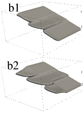
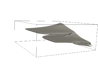
While in two dimensions, the Linear Elastic Facture Mechanics (LEFM) approach has been successful when describing crack propagation, its application to 3D systems has proven to be difficult. Indeed while in two dimensions, the crack front is a point and its shape cannot play any role in the propagation laws of the crack that relate the stress intensity factors to the velocity of the crack, in three dimensions, the crack front shape is a new degree of freedom and its shape may affect the propagation law. A typical example where the crack front shape is difficult to predict using the LEFM is the propagation of a crack under mixed mode (I +III). Indeed in this situation one expects that the cracks should eventually propagate in a way such that . Early experiments [1] have shown that under mixed mode loading, continuous crack fronts can be unstable and may become a set of discontinuous crack fronts leading to lance formation (an illustration of lances and échelon cracks is given in fig. 1 b,c, and d). Later theoretical [2, 3, 4, 5, 6, 7] work has shown that under the assumption that the crack propagates in such a way that , the initially flat crack front is linearly unstable in a periodic system along the crack front direction when the crack is under a load such that where is proportional to . While this is unambiguous, recent experiments [5, 8] indicate that even for high values of , smooth relaxation of the crack front toward a regime where is possible.
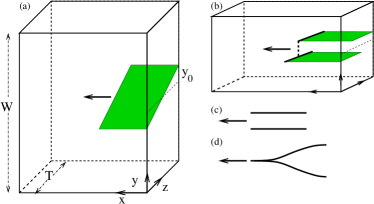
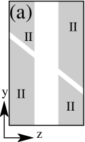
Indeed, in experiments by Lazarus[5], where an initially tilted crack crossing a finite thickness sample is considered (see fig. 1 a) there is first the initiation of multiple crack fronts from the initial crack. These fronts reconnect together after having propagating over a short distance leaving marks that can be described as lances on the crack surface. After their reconnection the continuous smooth crack front relaxes toward a configuration. The recent experiment of Ronsin [8] in the same configuration showed that a smooth relaxation of the crack front can be observed without the initial lances below a threshold tilt of the initial crack front. Above a threshold, crack front fragmentation occurs: an initially continuous (and smooth) crack front splits into a few (at most 5) discontinuous crack front that propagate parallel to each other thus forming échelon cracks. On the other hand, Pham [9] observed that under mixed mode loading crack front fragmentation always occurs in a configuration where a linear stability analysis in the spirit of [3] is difficult due to the complex evolution of the stress intensity factors and during the propagation of the crack. Moreover these experiments differ dramatically from the one of [1] since they consider finite thickness samples with free boundaries and not cylindrical samples that are topologically similar to infinite periodic systems.
Here numerical results on the propagation of an initially tilted crack in finite size samples under mode I loading are presented. They were obtained using the phase field model of crack propagation[10, 11, 12, 2] applied to 3D cracks and show that while the phase field model is able to reproduce well the smooth relaxation presented in [8], a more detailed description of the experimental details is needed to actually reproduce well front fragmentation. Moreover they indicate that the linear instability mechanism presented in[2, 3, 4, 5, 6, 7] may not be at play in finite size systems. The role of the initial crack is investigated and is shown to be a possible source of crack front fragmentation. Before turning to the results, the system considered and the phase field model are briefly described.
2 The phase Field model
The phase field approach is based on the introduction of an additional field , that describes the internal state of the material. It is equal to in intact regions, while it takes the value in broken regions. An adequate coupling between the elastic fields (the displacement) and the phase field is introduced so that the system has two stationary state solutions: one with where and strain is uniform, and one where in most of the system except in a region of finite width (independant of the system size) where goes smoothly close to zero where the strain is focused[10]. This is achieved through the introduction of a free energy functional of the form:
| (1) |
Where, , , , and are model parameters that are taken to be equal to 1 here (unless stated otherwise). is the elastic energy density in the limit of the linear elasticity:
| (2) |
Here is the stain tensor and and the Lamé coefficients.
The evolution equation for the displacement field and the phase field are then
| (3) | |||||
| (4) |
where is a kinetic parameter and prescribes the energy dissipation at the crack front as it has been numerically shown in [13]. The is a phenomenological dissipation term that has been introduced in order to damp elastic waves and to prevent dynamic crack instabilities such as branching to appear without being limited to small loading condition where lattice pinning effects are present. This term induces an increase of the fracture energy with its velocity as would an increase on the value of the kinetic parameter [13]. Typical velocities of cracks are of the order of where is the shear wave speed and simulations performed with higher load and velocities up to 0.3 lead to the same results.
The free parameters , and in eq.1 allow to choose at will both the fracture energy (denoted ) and the fracture width (denoted over which the phase field goes from 1 to ).Such an approach was initially proposed in [14] . Later a proper form of the coupling function allowing to fully relax stresses was proposed in [10]. Since then it has been widely used to study the branching instability [13, 15], the instabilities of cracks under mixed mode in periodic systems [2]. Very similar approaches [16] have gained popularity in solid mechanics and have been used to study crack propagation. While most studies have been limited to two dimensional systems, the conceptual ease of extending the phase field approach to three dimensional systems makes it a valuable tool to study crack front behaviour, a problem that has been proven to be difficult in the framework of LEFM. Typical example include the work of A. Pons on front fragmentation[2], the work of Sisic on cracks induced by a thermal gradient and [17] where simulations have been able to reproduce well hexagonal columnar joints.
Here the phase field model has been used in the geometry presented in figure 1. An elastic piece of material is submitted to mode I loading by imposing the displacement fields in :
| (5) | |||||
| (6) | |||||
| (7) |
and the mode mixity (I+III) at the crack front is due to the tilt of the initial crack half-plane with respect to the mid plane of the sample (). The finite thickness of the sample imposes the following boundary conditions at :
| (8) | |||
| (9) | |||
| (10) |
This choice of boundary condition differs dramatically from periodic boundary conditions and has been shown to affect the shape of the crack front [18, 19, 12]. In samples where the thickness is of the same order of magnitude as its width , it has been shown [19, 12] that it takes a V-Shape.
The boundary conditions at and are Dirichlet for the displacement fields and Neuman for the phase field and, in order to study crack propagation over long distances without using too large simulation grids, the simulation domain was shifted by one grid point order to keep the apex of the crack front close to the center of the simulation domain.
In addition into a small region of thickness (about 40 grid points to be compared with simulation domains of length 800) close to the boundaries and , a dissipative term term is introduced in the r.h.s. of eq. 4 where grows linearly from zero at to 0.4 at . This peculiar dissipative term was chosen to minimize acoustic wave reflexion at the boundaries. Simulations with values of multiplied by 2 show that it has no effect on the crack behaviour which is expected since it is only present in a region far from the crack front. One should note that this also indicates that the thread-mill described earlier has no effect on the crack propagation.
In order to ensure that the phase field interface thickness does not affect the results significantly, simulations were also performed with varying system size and a constant phase-field interface thickness, showing neither qualitative nor quantitative change. This indicates a good convergence of the model. In the next section, the results of this simulation setup in the case where the continuous crack front is stable and relaxes smoothly are described.
3 Results: the smooth relaxation
 |
Before turning to the result of simulations in the case of tilted crack, recent work by Ronsin et al in nonlinear elastic gels is briefly described. In their experiments at small tilting angle (below ) the crack front relaxed exponentially toward a flat crack front with a characteristic length that is proportional to the size of the sample. Above a threshold value ranging from to depending on the applied load the so called cross hatch instability[8] leads to crack front fragmentation: the propagation of two crack fronts approximately parallell to each other that leads to a step in the crack surface (the échelon crack). This step eventually either drifts toward one side (here: ) of the samples and vanishes or decreases leading to the reconnection of the two crack fronts. Moreover, however small the initial tilting angle is, the crack front relaxes toward a flat crack front without any subcritical behaviour.
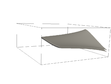
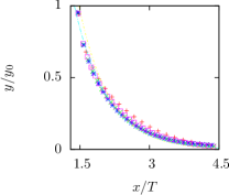
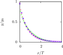
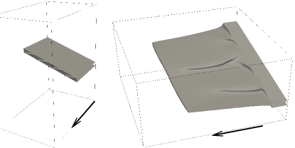
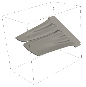
In good agreement with this, during the simulation performed using the phase field model, the smooth relaxation of the crack is actually observed as can be seen in figure 2 without any tilt concentration along the crack front. In addition, the trajectory of the intersection of the crack front with the sample boundary in the plane is well fitted by a decaying exponential. As in experiments these trajectories and the characteristic decay length are independent of the initial tilt for a given sample geometry. This is illustrated in fig. 3 (a) where , the distance from mid-plane has been renormalized by its initial value for different initial tilt angles. It can be seen that all curves collapse on a master curve. In addition, the effect of changing the sample geometry (i.e. its aspect ratio ) was also investigated and it appears that for aspect ratios ranging from 0.167 to 0.667 the decay length is proportional to and independent of at dominant order as it is illustrated in fig. 3 (b) where in addition to the normalization of by its initial value, is normalized by , is kept constant. These results are in good quantitative agreement with experimental data since the decay length measured here for an aspect ratio of is while in experiments (length was estimated using the value of at fig. 4b in [8]) it was found to be equal to .
| a | b |
|---|---|
 |
 |
Nevertheless, in contradiction with much experimental evidence, here an initially tilted planar front (below ) never propagated in a way leading to a discontinuous crack surface (independently of the system size or ). This threshold value corresponds to an initial mode mixity of the order unity while in both experiments and theoretical work the value of above which an instability develops is often much smaller (of the order 0.1).
 |
 |
One should keep in mind that in the simulation presented here, the threshold angle was independent of model parameters (keeping the fracture energy constant) such as the interface thickness111the interface thickness can be varied by changing the ratio between and both and or the ratio , indicating that the discrepancy between simulation results and experiments is not due to a poor convergence of the phase field model or to a peculiar choice of model parameters.
In the following a few arguments explaining the discrepancy between the results presented here and previous theoretical and experimental work is given. Thereafter a few possible mechanisms leading to crack front fragmentation are investigated numerically.
First, the main difference between the geometry used here and the periodic geometry used in other theoretical or numerical studies is that the smooth relaxation toward a flat crack front is possible. This induces an exponential decay of the mode mixity at the crack front. As a result, the driving force for the crack front linear instability decays and rapidly becomes smaller than the critical value above which the straight crack front is linearly unstable. Therefore any small perturbation of the initial crack front cannot grow over a sufficiently long time to reach a macroscopic amplitude. In addition, due to boundary conditions used here along the z-axis (no stress instead of periodic), the crack front is not flat but has a curved shape (here a V-shape). This could affect the result of a linear stability analysis and may prevent the existence of the unstable modes.
In order to check this last hypothesis simulations were performed in a setup where the tilted crack front cannot relax continuously due to a simple patterning of the material fracture energy (see: fig. 4). As a result, the mode mixity is kept constant during propagation unless the front breaks up into discontinuous lines so that the crack front in the central region can relax toward an horizontal line. These simulations show that for angles above the crack front can break up into three discontinuous crack fronts if the region where the free propagation is possible is large enough222the critical thickness of the free region was found to be independent of the fracture interface thickness and to depend on the imposed tilt angle .After breakup, the crack front propagating into the free region relaxes toward a flat surface and once the constraint is no longer present, the other two fronts can relax toward horizontal fronts, leading to the propagation of three parallel crack front that form two échelon crack. This shows that an instability mode of the crack front that can be related to the one depicted in [2, 6, 3] is present in the finite thickness sample. It also supports the hypothesis that the absence of front fragmentation in simulations presented here may be due to the fact that the unstable mode cannot grow sufficiently over the propagation length needed for the crack front to relax. This hypothesis is confirmed by simulations where the initial crack surface was perturbed:
| (11) |
where the sum is taken over 40 modes with random variables and , the amplitude of the perturbation. Indeed for angles as low as the crack front is unstable for sufficiently high (about a the value of for which, due to discretization, the initial crack surface is discontinuous in the phase field model ). This indicates that an initial finite perturbation of the crack front can lead to front fragmentation. Nevertheless the asymptotic behaviour of this system could not be investigated due to computational limitations.
In the following I present briefly an investigation of the effects of more dramatic alterations of the initial crack. This was motivated by a comparison between experiments and the linear instability mechanism that is usually proposed. Indeed, in the latter (except in [8]), the early stage is characterized by short wavelength facets at the onset of crack propagation that coarsen leading to macroscopic facets. This is unlikely to be due to a linearly unstable mode unless it has a very short wavelength and grows over a very short distance.. This leads us to investigate other mechanisms that could lead to crack front fragmentation and here attention is given to the possible effects of the initial fracture.
4 Effect of the initial condition on the fragmentation process
In all simulations presented previously the initial crack is rounded at its tip so that the initial crack front is well defined and continuous. Here we present simulations where the initial cracked region has a flat front with some protrusions in the direction of the crack propagation as illustrated in fig. 6-a. As a result many disconnected crack fronts can begin to propagate, leading possibly to discontinuous crack fronts propagation and eventually coarsening as reported for instance in[20].
For this purpose we consider initial slits whith thickness of roughly 5 times and at the surface of which a few irregularities are present: lines of crack with thickness and length 333flat and rounded initial slits, were also investigated, showing no significant difference from the approach described earlier. These simulations mimic the propagation of a crack front initiated by an initial slit machined in a solid with some imperfections and can also be seen as a caricature of a crack propagating in a medium where structural heterogeneities are present[8]. Due to computational limitations, these simulations have been restricted to systems where a small number of defects (at most 20) of the front are present. In the following the results are briefly described depending on the initial configuration. The simplest case considered is an initial front with two horizontal (i.e. constant) defects. The evolution of the crack front leads, after a short transient, to the growth of two well defined crack surfaces. In the situation where many ( ) initial cracks are present, the evolution of the crack front leads to the propagation of multiple, close to horizontal, crack surfaces that propagate forming well defined échelons cracks. During their propagation coarsening (here coalescence of two crack fronts and not elimination of a crack surface) leads to the propagation of a diminishing number of crack fronts that are separated by significantly higher gap) leading to patterns very similar to the one described in [1, 20, 2]. Nevertheless the setup and the hypothesis here are extremely different: the boundary conditions are no stress instead of periodic and the initial crack surface is significantly perturbed with asperities that act as nuclei for the crack front and not flat. This implies that the linear instability scenario is not the sole explanation for crack front fragmentation and that another possibility is the nucleation of multiple crack fronts either due to irregularities in the initially machined slit or to material inhomogeneities (this possibility was not investigated here) but has been shown to be very likely in [8] where the effect of the initial crack was carefully investigated and shown not to be significant.
5 Conclusion
In summary the propagation of a crack front under mixed mode loading in a finite sample with no stress boundary condition has been investigated. The results indicate that smooth relaxation of the initial crack front is observed below a threshold mode mixity (here tilt angle of the initial slit) that is below the one observed experimentally444Ronsin et al indicate that they have observed examples of smooth relaxation up to angles of unless the initial crack front is significantly perturbed. In this latter case, the crack propagation patterns are similar to those observed experimentally under various conditions where no stress boundary conditions are present. This indicates that the linear instability mechanism initially presented in [3] and further refined[4, 5, 2, 6] may not apply to situations where boundary conditions do not prevent the smooth relaxation of the front as observed experimentally. Moreover simulations where the initial slit is not uniform give a possible explanation for the front fragmentation observed in some experiments where the material is inhomogeneous (e.g. cavities already present in the material can act as perturbation of the crack front) or where the initial slit is inhomogeneous or thick compared to the process zone. This calls for experiments where both the defects of the initial slit and the structural inhomogeneities are controlled and have characteristic length scales that can be tuned as in[21].
Acknowledgements.
I wish to thank Allistair Rowe and Mathis Plapp for their useful comments on early version of the manuscript. I wish to thank O. Ronsin, T. Baumberger and C. Caroli for enlighting discussions on their experimental work at an early stage of this work.References
- [1] \NameSommer E. \REVIEWEngineering Fracture MechanicsI.
- [2] \NamePons A. J. Karma A. \REVIEWNature464201085.
- [3] \NameGao H. Rice J. R. \REVIEWJournal of Applied Mechanics531986774.
- [4] \NameLazarus V., Leblond J.-B. Mouchrif S.-E. \REVIEWJournal of the Mechanics and Physics of Solids4920011421.
- [5] \NameLazarus V., Leblond J.-B. Mouchrif S.-E. \REVIEWJournal of the Mechanics and Physics of Solids4920011399.
- [6] \NameLeblond J.-B., Karma A. Lazarus V. \REVIEWJournal of the Mechanics and Physics of Solids5920111872 .
- [7] \NameLazarus V., Buchholz F.-G., Fulland M. Wiebesiek J. \REVIEWInternational Journal of Fracture1532009141.
- [8] \NameRonsin O., Caroli C. Baumberger T. \REVIEWEPL (Europhysics Letters)105201434001.
- [9] \NamePham K. Ravi-Chandar K. \REVIEWInternational Journal of Fracture2014.
- [10] \NameKarma A., Kessler D. Levine H. \REVIEWPhysical Review Letters872001045501.
- [11] \NameHenry H. Levine H. \REVIEWPhys. Rev. Lett.932004105504.
- [12] \NameHenry H. \REVIEWEurophysics Letters92201046002.
- [13] \NameHenry H. \REVIEWEurophysics Letters83200816004.
- [14] \NameAranson I. S., Kalatsky V. A. Vinokur V. M. \REVIEWPhys Rev Lett852000118.
- [15] \NameKarma A. Lobkovsky A. E. \REVIEWPhys. Rev. Lett.922004245510.
- [16] \NameFrancfort G. Marigo J.-J. \REVIEWJournal of the Mechanics and Physics of Solids4619981319.
- [17] \NameBourdin B., Marigo J.-J., Maurini C. Sicsic P. \REVIEWPhys. Rev. Lett.1122014014301.
- [18] \NameBENTHEM J. \REVIEWInternational Journal of Solids and Structures131977479.
- [19] \NameBazant Z. P. Estenssoro L. F. \REVIEWInternational journal of solids and structure151979405.
- [20] \NameChen C.-H., Cambonie T., Lazarus V., Nicoli M., Pons A. J. Karma A. \REVIEWPhys. Rev. Lett.1152015265503.
- [21] \NameDalmas D., Lelarge A. Vandembroucq D. \REVIEWPhys. Rev. Lett.1012008255501.