Send correspondence to VSD – email: vik.dhillon@sheffield.ac.uk, tel: +44 114 222 4528
HiPERCAM: A high-speed, quintuple-beam CCD camera for the study of rapid variability in the Universe
Abstract
HiPERCAM is a high-speed camera for the study of rapid variability in the Universe. The project is funded by a €3.5M European Research Council Advanced Grant. HiPERCAM builds on the success of our previous instrument, ULTRACAM, with very significant improvements in performance thanks to the use of the latest technologies. HiPERCAM will use 4 dichroic beamsplitters to image simultaneously in 5 optical channels covering the bands. Frame rates of over 1000 per second will be achievable using an ESO CCD controller (NGC), with every frame GPS timestamped. The detectors are custom-made, frame-transfer CCDs from e2v, with 4 low-noise (2.5e-) outputs, mounted in small thermoelectrically-cooled heads operated at 180 K, resulting in virtually no dark current. The two reddest CCDs will be deep-depletion devices with anti-etaloning, providing high quantum efficiencies across the red part of the spectrum with no fringing. The instrument will also incorporate scintillation noise correction via the conjugate-plane photometry technique. The opto-mechanical chassis will make use of additive manufacturing techniques in metal to make a light-weight, rigid and temperature-invariant structure. First light is expected on the 4.2 m William Herschel Telescope on La Palma in 2017 (on which the field of view will be 10’ with a 0.3”/pixel scale), with subsequent use planned on the 10.4 m Gran Telescopio Canarias on La Palma (on which the field of view will be 4’ with a 0.11”/pixel scale) and the 3.5 m New Technology Telescope in Chile.
keywords:
instrumentation: detectors – instrumentation: photometers – techniques: photometric1 SCIENTIFIC MOTIVATION
The next few years will be witness to a revolution in our knowledge of the Universe with the advent of large survey facilities such as LSST, Gaia, PLATO, SKA and Euclid. Many new variable and transient sources will be discovered by these facilities. In the same time-frame, the hunt will be on for electromagnetic counterparts to the gravitational wave sources that LIGO has started to detect[1]. Time-domain astrophysics is set to become a core activity, and detailed follow-up studies of the most interesting objects will be essential. The world’s major ground-based telescopes provide facilities for such follow-up work, but one area is currently poorly catered for – high time-resolution (millisecond to second) optical cameras.
High time-resolution probes the most extreme cosmic environments – white dwarfs, neutron stars and black holes – testing theories of fundamental physics to their limits. For example, black holes and neutron stars give us the chance to study the effects of strong-field general relativity, and neutron stars and white dwarfs enable the study of exotic states of matter predicted by quantum mechanics[2]. Black holes, neutron stars and white dwarfs are also a fossil record of stellar evolution, and the evolution of such objects within binaries is responsible for some of the Galaxy’s most exotic and scientifically-valuable inhabitants, such as binary millisecond pulsars and type Ia supernovae.
One of the best ways of studying compact stellar remnants is through their multi-colour photometric variability. The dynamical timescales of black holes, neutron stars and white dwarfs range from milliseconds to seconds. This means that the rotation and pulsation of these objects, and the motion of any material in close proximity to them (e.g. in an accretion disc), tends to occur on such short timescales. Hence, only by observing at high speeds can the variability of compact objects be resolved, thereby revealing a wealth of information, such as their structure, radii, masses and emission mechanisms[3].
Observing the Universe on timescales of milliseconds to seconds is also of benefit when studying less massive compact objects, such as exoplanets[4], brown dwarfs[5] and Solar System objects[6]. Despite varying on timescales of minutes rather than seconds, observing the eclipses and transits of exoplanets at high time-resolution can hugely improve throughput through the avoidance of detector readout-time, and enables the detection of Earth-mass planets through small variations in transit timing. Simultaneous, multi-band light curves of the transits of exoplanets are sensitive to wavelength-dependent opacity sources in their atmospheres, especially in low-gravity exoplanets, as will be found by the next generation of exoplanet surveys. Within the Solar System, high time-resolution occultation observations enable shape/size measurements and the detection of atmospheres and ring systems, at spatial scales (0.5 milliarcsec) only otherwise achievable from dedicated space missions.
In this paper, we describe a new high-speed camera called HiPERCAM that has been designed to study compact objects of all classes, including black holes, neutron stars, white dwarfs, brown dwarfs, exoplanets and the minor bodies of the Solar System. The resulting data will enable us to help answer the questions: What are the progenitors of type Ia supernovae? What are the properties of exoplanet atmospheres? What is the equation of state of the degenerate matter found in white dwarfs and neutron stars? What is the nature of the flow of matter close to the event horizon of black holes? What gravitational wave signals are likely to be detected by the next generation of space and ground-based detectors? What are the properties of the dwarf planets in the Kuiper belt?
2 DESIGN
The design of HiPERCAM is based on our successful predecessor instrument, ULTRACAM[7], but offers a very significant advance in performance, as shown in Table 1 and described in the following sections.
| ULTRACAM | HiPERCAM | Notes | |
|---|---|---|---|
| Number of simultaneous colours | 3 () | 5 () | |
| Readout noise | 3.0 e- at 100 kHz | 2.5 e- at 200 kHz | pixel rates in kHz |
| CCD temperature | 233 K | 180 K | |
| Dark current | 360 e-/pix/hr | 6 e-/pix/hr | |
| Longest exposure time | 30 s | 1800 s | |
| Highest frame rate | 400 Hz | 1600 Hz | 2424 pix windows, bin 44 |
| Field of view on WHT | 5.1’ | 10.2’ | platescale 0.3”/pixel |
| Field of view on VLT | 2.6’ | – | 0.15”/pixel (ULTRACAM) |
| Field of view on GTC | – | 3.9’ | 0.113”/pixel (HiPERCAM) |
| Probability of comparison | 52% | 95% | WHT, galactic latitude = 30∘ |
| Scintillation correction | No | Yes | |
| Dummy CCD outputs | No | Yes | |
| Deep depletion | No | Yes | |
| QE at 700/800/900/1000 nm | 83%/61%/29%/5% | 91%/87%/58%/13% | |
| Fringe suppression CCDs | No | Yes | |
| Fringe amplitude at 900 nm | 10% | 1% |
2.1 Optics
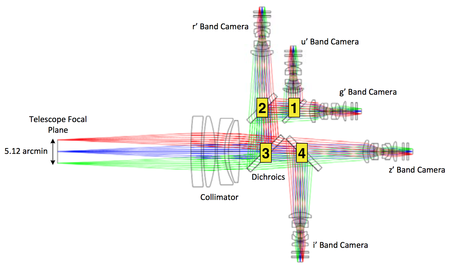
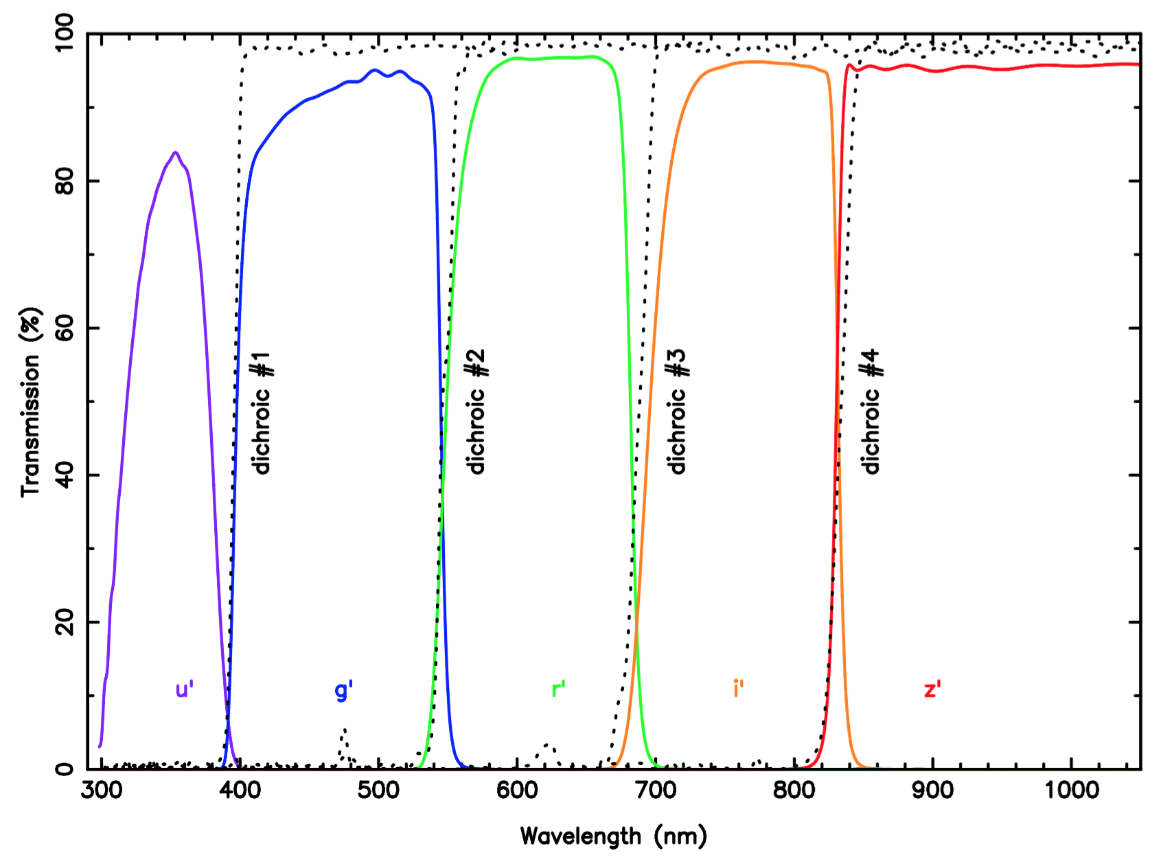
The HiPERCAM optical design is shown in Fig. 1. Light from the telescope is first collimated and then split into five arms using four dichroic beamsplitters. The beam in each arm then passes through a re-imaging camera, which focuses the light through a bandpass filter and cryostat window onto a CCD. The bandpasses of the five arms are defined by SDSS filters (Fig. 2), although narrow-band filters that lie within these five bandpasses can also be used. The collimator shown in Fig. 1 has been designed for use on both the 4.2 m William Herschel Telescope (WHT) on La Palma and the 3.5 m New Technology Telescope (NTT) on La Silla, giving a platescale of 0.3”/pixel and 0.35”/pixel, respectively, and a field of view of 10.2’ and 12.0’, respectively. On the WHT, HiPERCAM will have a 95% chance of observing a comparison star of magnitude in the field of view (at a galactic latitude of 30∘) for differential photometry. A second collimator for use on the 10.4 m Gran Telescopio de Canarias (GTC) has also been designed, giving a platescale of 0.113”/pixel and a field of view of 3.9’. When switching between telescopes, only the collimator needs to be changed – no other optics need to be added, removed or re-aligned.
 |
 |
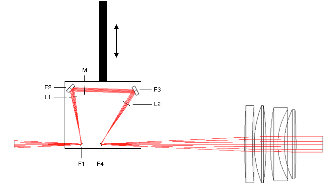
HiPERCAM also incorporates a scintillation corrector, which exploits the Conjugate-Plane Photometry technique [8, 9]. The optical layout of the scintillation corrector is depicted in Fig. 3. Light from the target star is picked off by a flat lying just above the focal plane of the telescope, collimated and then masked at the conjugate altitude of the turbulent layer. The beam is then re-imaged in such a way that a second flat lying just below the focal plane of the telescope returns the beam into HiPERCAM with an identical focal ratio and focal point as an unperturbed beam. Hence, as far as HiPERCAM is concerned, the pick-off system is “transparent”. Two such pick-offs will be required, one for the target star and another for the comparison star.
 |
2.2 Detectors
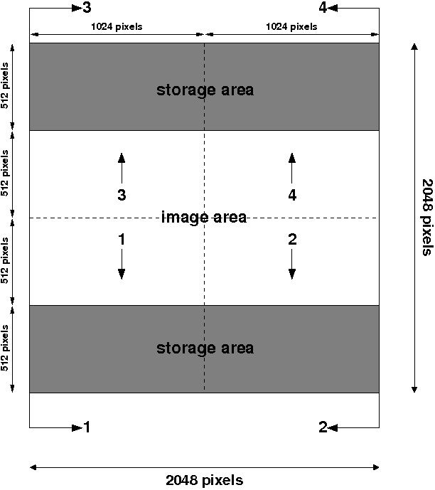 |
HiPERCAM will employ 5 custom-designed CCD231-42 CCDs from e2v. Each CCD is a frame-transfer device with 15 m pixels and 4 low-noise outputs, with one output located on each corner. The CCDs have a format of 20482048 pixels, where the upper 2048512 and lower 2048512 pixels are masked off as frame-transfer storage regions, providing an image area of 20481024 pixels. Hence each CCD output processes a quadrant of format 1024512 pixels, as shown in Fig. 4.
The HiPERCAM CCD231-42 CCDs are back-illuminated and thinned for high quantum efficiency (QE). The CCD has an Astro Broadband anti-reflection (AR) coating, and the and CCDs have the Astro Multi-2 AR coating. The and CCDs are manufactured from standard silicon, whereas the and CCDs are manufactured from deep depletion silicon to maximise red QE. The and CCDs also incorporate e2v’s fringe suppression process. This breaks the interference condition by introducing irregularities in the back surface of the device, reducing fringing to approximately the same level as the flat-field noise [10].
To maximise readout speed and minimise noise, the HiPERCAM CCDs are equipped with: low noise outputs of 2.5 e- at 200 kHz; dummy outputs to eliminate pickup noise; fast row (vertical) clocking of 8 s/row; fast serial (horizontal) clocking of 0.1 s/pixel; the ability to clock the serial register of each quadrant independently in order to enable efficient windowing modes[7]; two-phase image and storage clocks to minimise the frame-transfer time.
We have decided to use non inverted-mode (NIMO) rather than inverted-mode (AIMO) devices in HiPERCAM, for three reasons. First, NIMO devices can be clocked more quickly. Second, although both AIMO and NIMO devices can have similar mean dark current specifications at their optimum operating temperatures, our experience with ULTRASPEC (NIMO[11]) and ULTRACAM (AIMO[7]) is that the dark current in NIMO devices is much more uniformly distributed than in AIMO CCDs; the dark current in the latter is predominantly in the form of numerous hot pixels which do not subtract well using dark frames, making exposures longer than s undesirable. Third, and most importantly, we chose to use NIMO devices in HiPERCAM because we wish to use deep-depletion silicon in the red CCDs to maximise QE and this in incompatible with inverted-mode operation.
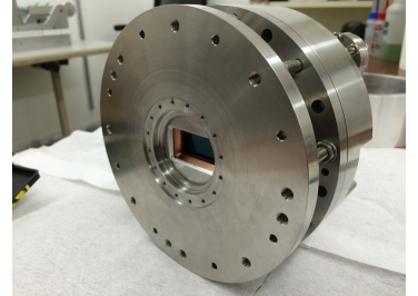
The consequence of selecting NIMO devices for HiPERCAM is that the detectors need to be cooled to 180 K or below to ensure that the dark current is less than 360 e-/pixel/hr, which corresponds to 10% of the faintest sky level we will record with HiPERCAM (set by observations in the -band in dark time on the GTC). Cooling to 180 K will therefore ensure dark current is always a negligible noise source in HiPERCAM. To achieve 180 K, we looked at a number of cooling options. We eliminated liquid nitrogen as impractical: incorporating five liquid-nitrogen cryostats would make HiPERCAM large, heavy, and very time-consuming to fill each night (automatic filling or continuous flow systems are not an option given that HiPERCAM will be a visitor instrument). We also eliminated closed-cycle Joule-Thomson coolers, such as the CryoTiger, due to the impracticality of housing up to 5 compressors at the telescope and passing up to 10 stainless-steel braided gas lines through the cable wrap. We seriously considered Stirling coolers, but were concerned about the vibrations that they induce in the telescope. These vibrations can be reduced through careful choice of cooler and the use of complex, bulky anti-vibration mounts [12], but even with these precautions in place, it would have been difficult to persuade the potential host telescopes to accept HiPERCAM with Stirling coolers due to the residual vibrations. Eventually, following extensive prototyping and testing, we decided to use thermo-electric (peltier) coolers (TECs), which are the simplest, cheapest, lightest and most compact of all of the cooling options. By using two five-stage TECs in conjunction with careful control of the parasitic heat load on the detector, we have been able to build a CCD head that can achieve the target detector temperature of 180 K. The heat generated by the TECs is extracted using a 278 K water-glycol cooling circuit. The interior of the head has also been carefully designed to maximise the lifetime of the vacuum – we anticipate a hold time of years. A photograph of one of the heads is shown in Fig. 5.
 |
2.3 Mechanics
The HiPERCAM opto-mechanical chassis (Fig. 6) is a triple octopod composed primarily of 3 large aluminium plates connected by carbon fibre struts, and incorporating some components made using additive manufacturing techniques in metal (titanium and invar). The design results in a stiff, compact (1.25 m long), light-weight (200 kg) and open structure, which is relatively insensitive to temperature variations. These characteristics are essential for visitor instruments, as they make HiPERCAM easy to maintain, transport and mount/dismount at the telescope.
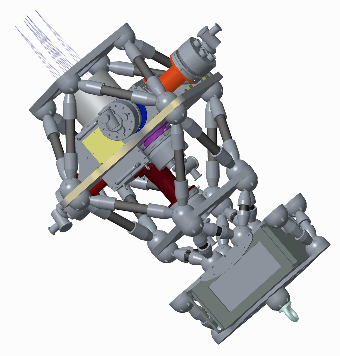 |
The dichroics, lens barrels, filters and CCDs are housed in/on an aluminium hull, which forms a sealed system to light and dust. The hull is affixed to the large central aluminium plate shown in Fig. 6. The top plate connects the instrument to the telescope, and the CCD controller is mounted on the bottom plate.
2.4 Data acquisition system
The HiPERCAM data acquisition system is designed to be detector limited, i.e. the throughput of data from the output of the CCDs to the hard disk on which it is eventually archived is always greater than the rate at which the data comes off the CCDs. This means that the instrument is capable of running continuously all night at its maximum data rate without ever having to pause for archiving of data.
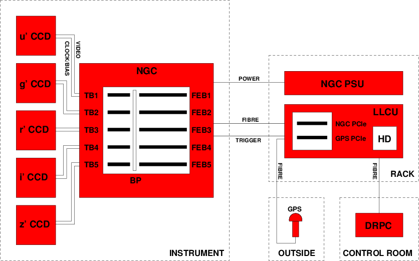 |
Fig. 7 shows a schematic of the HiPERCAM data acquisition system. The architecture is similar to that developed for ULTRACAM[7], but uses much more up-to-date, faster hardware. The heart of the system is a European Southern Observatory (ESO) New General detector Controller (NGC)[13]. The HiPERCAM NGC is composed of a six-slot housing containing 5 Front-End Basic (FEB) Boards and 5 Transition Boards (TB). Each FEB is connected to a back plane (BP) and is accompanied by a TB, which handles all external connections to the FEB. Each TB is connected to a CCD head via a single cable, carrying both the clocks/biases from the clock/bias-driver on the associated FEB and the CCD video signal to the four ADC channels on the FEB. The NGC is located on the instrument itself (see Fig. 6) in order to minimise the length of the cables running to each CCD head for noise reduction.
The NGC is powered by a separate Power Supply Unit (PSU), which is located in an electronics rack, approximately 2–5 m away from the instrument. The rack also contains the Linux Local Control Unit (LLCU) for the NGC, which is a linux PC provided by ESO containing the NGC Peripheral Computer Interconnect Express (PCIe) card. The NGC PCIe card is connected to the NGC via fibre, through which it is possible to control the NGC and receive data. In addition to the system disk, the LLCU contains a large-capacity hard disk (HD) on which the raw CCD data are written.
The LLCU also contains a GPS PCIe card, which accepts two inputs. The first input is a trigger that is generated by the NGC whenever an exposure finishes. This trigger will cause the GPS card to write a timestamp to its FIFO (First In, First Out buffer), which is then written to the header of the corresponding CCD frame. The second input is a GPS signal from an external antenna. The external antenna will be connected to the GPS card in the LLCU via a fibre-converter that enables long cable runs to outside the dome and isolates the telescope from lightning strikes.
A second linux PC, referred to as the Data Reduction PC (DRPC) in Fig. 7, will be located in the telescope control room. This PC will run, amongst other things, the data reduction pipeline, the instrument-control GUI, the data logger and the target acquisition tool. It will be connected to the LLCU via fibre ethernet.
2.5 Performance
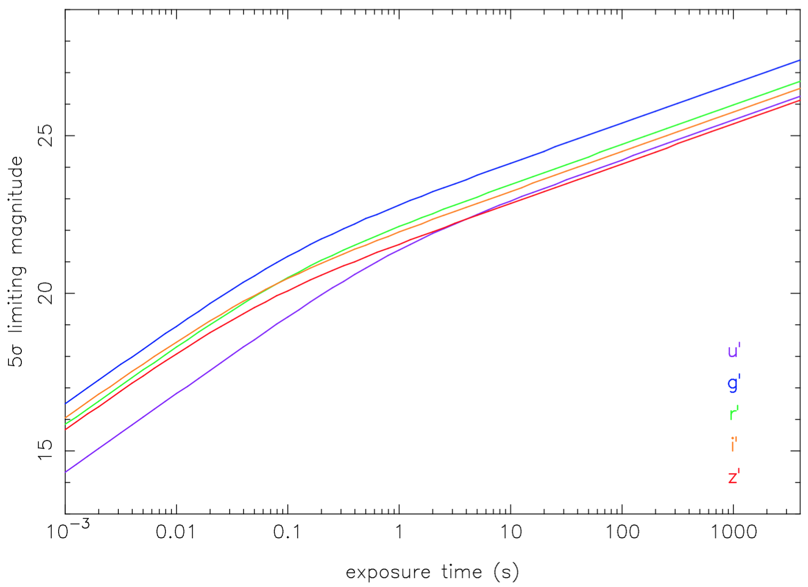
Fig. 8 shows the predicted 5σ limiting magnitudes achievable with HiPERCAM on the GTC as a function of exposure time. The calculations are based on the measured zeropoints for ULTRACAM on the WHT[7], but scaled for: the increased telescope aperture of the GTC; the extra reflection off the Nasmyth flat at the GTC; the improved dichroics and AR coatings used in HiPERCAM; the superior red QEs of the CCDs in HiPERCAM. The calculations also assume dark moon, observing at the zenith and seeing of 0.8”. It can be seen that it should be possible to achieve a limiting magnitude of in a single 0.001 s exposure, in 1 s, and in 1800 s.
 |
Due to the fast vertical clocking time and split-frame transfer architecture of the CCDs in HiPERCAM, the dead time between exposures in standard readout mode will be only 0.004 s, a factor of 6 times less than ULTRACAM. However, substantially lower dead times will be available in drift mode[7], where the windows are positioned on the border between the image and storage areas and, instead of vertically clocking the entire image area into the storage area, only the window is clocked into the (top of) the storage area. In drift mode, we predict frame rates of 1600 Hz using four pixel windows, binned , for example. This is a factor of 4 times quicker than ULTRACAM, and is primarily due to the much faster horizontal clocking provided by the NGC and the CCDs used in HiPERCAM.
3 CONCLUSIONS
We have described the scientific motivation, design and predicted performance of HiPERCAM. The instrument offers a significant advance on what has come before in the field of high time-resolution optical instrumentation. First light is planned for 2017 on the 4.2 m WHT, with subsequent use planned on the 10.4 m GTC later that year.
Acknowledgements.
HiPERCAM is funded by the European Research Council under the European Union’s Seventh Framework Programme (FP/2007-2013) under ERC-2013-ADG Grant Agreement no. 340040 (HiPERCAM). We would like to thank our major suppliers for their assistance with this project: Amptown, Asahi Spectra, e2v, ESO, Fluidic, Huber, Labtex, Meerstetter, MKS Instruments, Newport, Rocky Mountain Instruments, Staubli, Steatite, Titan Enterprises, Universal Cryogenics.References
- [1] B. P. Abbott, R. Abbott, T. D. Abbott, M. R. Abernathy, F. Acernese, K. Ackley, C. Adams, T. Adams, P. Addesso, R. X. Adhikari, and et al., “Observation of Gravitational Waves from a Binary Black Hole Merger,” Physical Review Letters 116, p. 061102, Feb. 2016.
- [2] J. Antoniadis, P. C. C. Freire, N. Wex, T. M. Tauris, R. S. Lynch, M. H. van Kerkwijk, M. Kramer, C. Bassa, V. S. Dhillon, T. Driebe, J. W. T. Hessels, V. M. Kaspi, V. I. Kondratiev, N. Langer, T. R. Marsh, M. A. McLaughlin, T. T. Pennucci, S. M. Ransom, I. H. Stairs, J. van Leeuwen, J. P. W. Verbiest, and D. G. Whelan, “A Massive Pulsar in a Compact Relativistic Binary,” Science 340, p. 448, Apr. 2013.
- [3] P. Gandhi, S. P. Littlefair, L. K. Hardy, V. S. Dhillon, T. R. Marsh, A. W. Shaw, D. Altamirano, M. D. Caballero-Garcia, J. Casares, P. Casella, A. J. Castro-Tirado, P. A. Charles, Y. Dallilar, S. Eikenberry, R. P. Fender, R. I. Hynes, C. Knigge, E. Kuulkers, K. Mooley, T. Muñoz-Darias, M. Pahari, F. Rahoui, D. M. Russell, J. V. Hernández Santisteban, T. Shahbaz, D. M. Terndrup, J. Tomsick, and D. J. Walton, “Furiously fast and red: sub-second optical flaring in V404 Cyg during the 2015 outburst peak,” MNRAS 459, pp. 554–572, June 2016.
- [4] T. R. Marsh, S. G. Parsons, M. C. P. Bours, S. P. Littlefair, C. M. Copperwheat, V. S. Dhillon, E. Breedt, C. Caceres, and M. R. Schreiber, “The planets around NN Serpentis: still there,” MNRAS 437, pp. 475–488, Jan. 2014.
- [5] S. P. Littlefair, V. S. Dhillon, T. R. Marsh, B. T. Gänsicke, J. Southworth, and C. A. Watson, “A Brown Dwarf Mass Donor in an Accreting Binary,” Science 314, pp. 1578–, Dec. 2006.
- [6] J. L. Ortiz, B. Sicardy, F. Braga-Ribas, A. Alvarez-Candal, E. Lellouch, R. Duffard, N. Pinilla-Alonso, V. D. Ivanov, S. P. Littlefair, J. I. B. Camargo, M. Assafin, E. Unda-Sanzana, E. Jehin, N. Morales, G. Tancredi, R. Gil-Hutton, I. de La Cueva, J. P. Colque, D. N. da Silva Neto, J. Manfroid, A. Thirouin, P. J. Gutiérrez, J. Lecacheux, M. Gillon, A. Maury, F. Colas, J. Licandro, T. Mueller, C. Jacques, D. Weaver, A. Milone, R. Salvo, S. Bruzzone, F. Organero, R. Behrend, S. Roland, R. Vieira-Martins, T. Widemann, F. Roques, P. Santos-Sanz, D. Hestroffer, V. S. Dhillon, T. R. Marsh, C. Harlingten, A. Campo Bagatin, M. L. Alonso, M. Ortiz, C. Colazo, H. J. F. Lima, A. S. Oliveira, L. O. Kerber, R. Smiljanic, E. Pimentel, B. Giacchini, P. Cacella, and M. Emilio, “Albedo and atmospheric constraints of dwarf planet Makemake from a stellar occultation,” Nature 491, pp. 566–569, Nov. 2012.
- [7] V. S. Dhillon, T. R. Marsh, M. J. Stevenson, D. C. Atkinson, P. Kerry, P. T. Peacocke, A. J. A. Vick, S. M. Beard, D. J. Ives, D. W. Lunney, S. A. McLay, C. J. Tierney, J. Kelly, S. P. Littlefair, R. Nicholson, R. Pashley, E. T. Harlaftis, and K. O’Brien, “ULTRACAM: an ultrafast, triple-beam CCD camera for high-speed astrophysics,” MNRAS 378, pp. 825–840, July 2007.
- [8] J. Osborn, R. W. Wilson, V. S. Dhillon, R. Avila, and G. D. Love, “Conjugate-plane photometry: reducing scintillation in ground-based photometry,” MNRAS 411, pp. 1223–1230, Feb. 2011.
- [9] J. Osborn, D. Föhring, V. S. Dhillon, and R. W. Wilson, “Atmospheric scintillation in astronomical photometry,” MNRAS 452, pp. 1707–1716, Sept. 2015.
- [10] S. M. Tulloch, “Investigation of Low Fringing Detectors on the ISIS Spectograph,” ING Technical Note 130, June 2005.
- [11] V. S. Dhillon, T. R. Marsh, D. C. Atkinson, N. Bezawada, M. C. P. Bours, C. M. Copperwheat, T. Gamble, L. K. Hardy, R. D. H. Hickman, P. Irawati, D. J. Ives, P. Kerry, A. Leckngam, S. P. Littlefair, S. A. McLay, K. O’Brien, P. T. Peacocke, S. Poshyachinda, A. Richichi, B. Soonthornthum, and A. Vick, “ULTRASPEC: a high-speed imaging photometer on the 2.4-m Thai National Telescope,” MNRAS 444, pp. 4009–4021, Nov. 2014.
- [12] G. Raskin, J. Morren, W. Pessemier, J. Perez Padilla, and J. Vandersteen, “Compact Stirling cooling of astronomical detectors,” arXiv:1311.0685 , Nov. 2013.
- [13] D. Baade, A. Balestra, C. Cumani, S. Eschbaumer, G. Finger, C. Geimer, L. Mehrgan, M. Meyer, J. Stegmeier, J. Reyes, and M. Todorovic, “NGC – ESO’s New General Detector Controller,” The Messenger 136, pp. 20–24, June 2009.