Octahedral rotation patterns in strained EuFeO3 and other perovskite films: Implications for hybrid improper ferroelectricity
Abstract
We report the relationship between epitaxial strain and the crystallographic orientation of the in-phase rotation axis and -site displacements in -type perovskite films. Synchrotron diffraction measurements of EuFeO3 films under strain states ranging from 2 % compressive to 0.9 % tensile on cubic or rhombohedral substrates exhibit a combination of and rotational patterns. We compare the EuFeO3 behavior with previously reported experimental and theoretical work on strained -type films on non-orthorhombic substrates, as well as additional measurements from LaGaO3, LaFeO3, and Eu0.7Sr0.3MnO3 films on SrTiO3. Compiling the results from various material systems reveals a general strain dependence in which compressive strain strongly favors and rotation patterns and tensile strain weakly favors structures. In contrast, EuFeO3 films grown on -type GdScO3 under 2.3 % tensile strain take on a uniform rotation pattern imprinted from the substrate, despite strain energy considerations that favor the pattern. These results point to the use of substrate imprinting as a more robust route than strain for tuning the crystallographic orientations of the octahedral rotations and -site displacements needed to realize rotation-induced hybrid improper ferroelectricity in oxide heterostructures.
pacs:
61.05.cp, 77.55.Px, 68.60.-pI Introduction
Epitaxial heterostructures of O3 perovskite oxides have attracted considered interest as a route toward altering or enhancing properties through epitaxial strain, superlattice formation, and interfacial phenomena.Schlom et al. (2008); Hwang et al. (2012a); Zubko et al. (2011); Bhattacharya and May (2014) Recently, the control of local atomic structure, in particular O6 octahedral distortions and rotations and -site displacements, has emerged as a promising strategy for designing functional properties in perovskite films.Bousquet et al. (2008); Rondinelli et al. (2012); Benedek et al. (2012); Moon et al. (2014a) One example of structure-driven design in oxide heterostructures is the prediction of hybrid improper ferroelectricity in (O3)/(O3) superlattices where both O3 and O3 are perovskites that exhibit the orthorhombic structure in bulk.Rondinelli and Fennie (2012); Mulder et al. (2013); Ghosh et al. (2015); Benedek et al. (2015) In such superlattices, the inequivalent displacements of the and cations produce a ferrielectric state. This design principle is predicated on the -site displacements occuring within the plane of the superlattice, perpendicular to the superlattice growth direction. A similar design approach has been used to predict that (SrRuO3)1/(CaRuO3)1 superlattices are polar metals.Puggioni and Rondinelli (2014)
A key challenge for experimentally verifying such predictions lies in the quantitative measurement of octahedral behavior and -site positions in thin films, as the primary technique used in bulk perovskites - powder diffraction - is not accessible in studies of epitaxial films. Recent work has shown the promise of synchrotron diffraction,May et al. (2010); Chang et al. (2011); Rotella et al. (2012); Johnson-Wilke et al. (2013); Lu et al. (2013); Fister et al. (2014); Zhang et al. (2014); Zhai et al. (2014); Biegalski et al. (2014) coherent Bragg rod analysis,Fister et al. (2014); Kumah et al. (2014) electron microscopy,Jia et al. (2009); Borisevich et al. (2010); Aso et al. (2014a) and electron diffractionHwang et al. (2012b) to probe octahedral rotations in perovskite films. In particular, the synchrotron diffraction approach is based on the measurement of half-order Bragg peaks that arise from the unit cell doubling nature of the octahedral rotations.Glazer (1975); Reaney and Woodward (2005) The presence and absense of specific half-order peaks is a direct signature of the pattern of octahedral rotations within the material. The rotation pattern is denoted using Glazer notation, in which in-phase, out-of-phase, or absense of rotations are signified by +, -, or 0 superscripts, respectively, along a given pseudocubic direction.Glazer (1972); Woodward (1997a) Axes with equal rotational magnitude are denoted by the same letter. For example, the pattern consists of equal out-of-phase rotation angles along all three pseudocubic axes, while the pattern has equivalent out-of-phase rotations along two axes and an in-phase rotation of differing magnitude along the third axis. This latter pattern corresponds to the orthorhombic perovskite structural variation, which is one of the most common crystal structures for oxide perovskites.Thomas (1989); Woodward (1997b) Materials in this structure also exhibit -site displacements in the plane normal to the in-phase rotation axis.
There is limited understanding of what determines the direction of the in-phase rotation axis, and therefore the -site displacements, in epitaxial -type perovskite films and superlattices despite the clear importance of this knowledge for the realization of new ferroic materials. While there have been numerous reports of the rotation pattern within a single film,Copie et al. (2013); Proffit et al. (2008); Choi et al. (2010); Han et al. (2009); Kan et al. (2013) systematic experimental studies probing the effect of a single variable, such as strain or composition, on the rotation pattern in -type films are lacking.
In this work, we report on the rotation patterns of strained EuFeO3 films, a perovskite that exhibits the structure in bulk form.Marezio et al. (1970) These results are compared with previously reported experimental and theoretical work on strained -type films, as well as new measurements from LaGaO3, LaFeO3, and Eu0.7Sr0.3MnO3 films, revealing a general strain dependence in which compressive strain strongly favors and rotation patterns and tensile strain weakly favors structures. However, EuFeO3 grown on orthorhombic GdScO3 (110) exhibits a uniform orientation matching that of the substrate, despite the 2.3 % tensile strain imposed by the substrate. This result indicates that the use of substrate templating is a more deterministic route than strain for controlling the in-phase rotation axis and -site displacement orientation in perovskite films and superlattices.
II Experimental Techniques
EuFeO3 films were grown on SrTiO3 (STO) (001), (LaAlO3)0.3(Sr2AlTaO6)0.7 (LSAT) (001), LaAlO3 (LAO) (001), and GdScO3 (GSO) (110) substrates using oxide molecular beam epitaxy (MBE). The growth conditions are described in Ref. Choquette et al., 2015. The thickness of the EuFeO3 films are between 35-40 unit cells (13-15 nm) thick as determined from x-ray diffraction. LaFeO3 and Eu0.7Sr0.3MnO3 films were also deposited by MBE on STO (001) using conditions reported in Ref. Scafetta et al., 2013 and Ref. Moon et al., 2014b, respectively. The LaGaO3 film was grown on STO (001) using pulsed laser deposition as described in Ref. Perna et al., 2010. The LaGaO3, Eu0.7Sr0.3MnO3, and LaFeO3 films are 25, 40, and 129 unit cells thick, respectively. A previously published reciprocal space map from this LaFeO3 film confirms that it is coherently strained to the STO substrate.Scafetta et al. (2013) Synchrotron diffraction measurements were performed at Sector 33-BM-C of the Advanced Photon Source. All measurements were carried out at room temperature. Photon energies of 15.5 keV and 16 keV were used for the EuFeO3 and Eu0.7Sr0.3MnO3 measurements, respectively. The LaGaO3 and LaFeO3 films were measured with 10 keV photons. The GenX software packageBjörck and Andersson (2007) was used to simulate the measured () data, from which -axis parameters and film thicknesses were obtained. Volume fractions of different structural orientations were obtained by analyzing peak areas after applying Lorentz polarization and beam footprint corrections.
III EuFeO3 Films
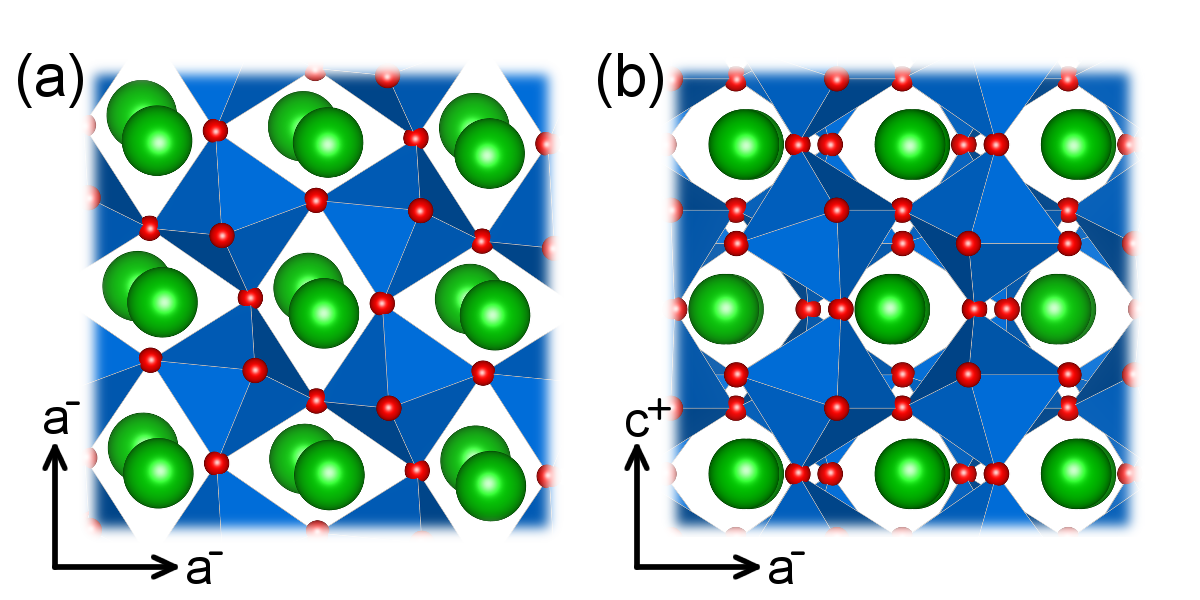
The orthorhombic structure is one of the most common perovskite variants among oxides and is the structure exhibited by bulk EuFeO3 at room temperature. Within the thin film community, the orthorhombic lattice is commonly converted to a pseudocubic structure in which the orthorhombic [100] is equivalent to the pseudocubic [110] and . The [001] direction is unchanged but the pseudocubic -axis parameter is half that of the orthorhombic -axis parameter. This pseudocubic lattice will be used throughout this work. Two key features of this structure, shown in Fig. 1, are the presence of the rotation pattern and -displacements. The rotation pattern indicates out-of-phase O6 rotations about two in-plane directions (pseudocubic [100] and [010]) and in-phase rotations along the out-of-plane [001] direction. The -site cations are displaced within the plane perpendicular to the rotation axis along directions close to the <110>. Both the octahedral rotations and -site displacements act to double the pseudocubic unit cell, leading to half-order diffraction peaks. Throughout this work, we will denote the growth direction as the -axis of the film. The pattern indicates the in-phase axis lies along an in-plane film direction. The pattern indicates that the in-phase axis lies along the out-of-the-plane film direction (the growth direction). In this study, we do not quantify the rotation angles and therefore cannot distinguish between and . We use throughout this work with the understanding that this entails both and . However, for films grown on STO, LAO, and LSAT substrates, we anticipate that the in-plane rotations, and , are equal due to the same in-plane lattice constants along the and -axes. For films on orthorhombic GSO, inequivalent and angles would be expected leading to or patterns because the in-plane lattice constants of the substrate are not identical.
The bulk structure of EuFeO3 has previously been determined from powder diffraction measurements.Marezio et al. (1970) It has pseudocubic lattice parameters, taken from the Fe-Fe distances of 3.882 Å along the axes and 3.842 Å along the axis (the orthorhombic long axis). The reduced - distance along the in-phase axis compared to the out-of-phase axes is a common feature of the structure, having also been reported in bulk LaFeO3,Falcon et al. (1997) LaGaO3,Vasylechko et al. (1999), LaTiO3,Komarek et al. (2007) LaVO3,Bordet et al. (1993) LaCrO3,Tezuka et al. (1998) CaTiO3,Liu and Liebermann (1993) CaFeO3,Takeda et al. (2000) and CaMnO3.Chmaissem et al. (2001) Based solely on these distances, one would expect the in-phase axis to lie out-of-the-plane () for films under tensile strain and in-the-plane ( or ) for films under compressive strain in order to minimize the lattice mismatch with the substrate.
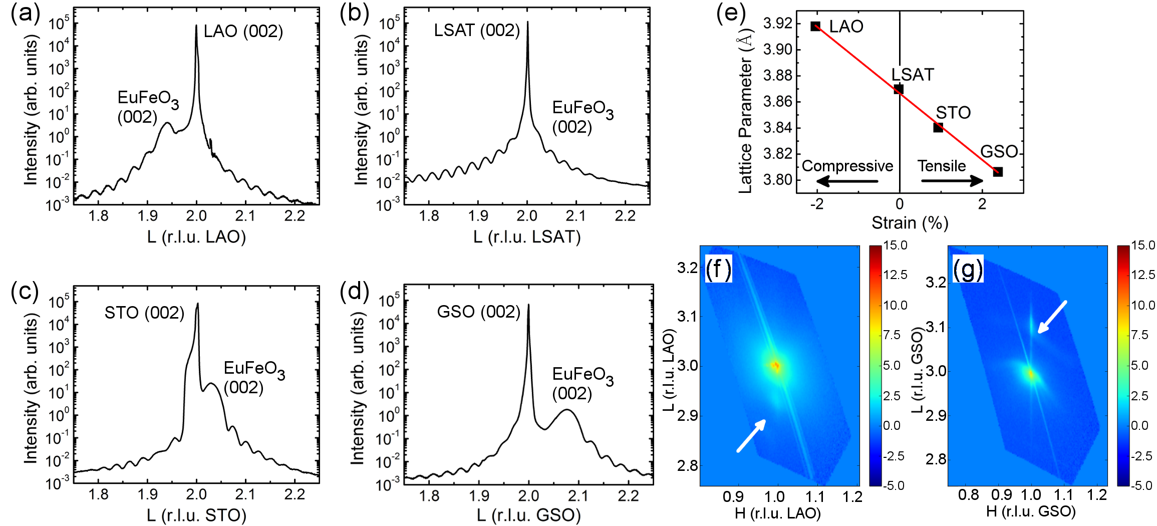
EuFeO3 films were deposited on a variety of commercially available substrates. The lattice mismatch between EuFeO3 and the substrates leads to an average 2% compressive strain on LAO (lattice parameter 3.791 Å), <0.1% strain on LSAT (3.868 Å), 0.9% tensile strain on STO (3.905 Å), and 2.3% tensile strain on GSO (3.968 Å). The measured scans are shown in Fig. 2(a-d). The obtained EuFeO3 -axis parameters are 3.918 Å on LAO, 3.840 Å on STO, 3.869 Å on LSAT, and 3.806 Å on GSO, consistent with the strain states of the films, shown in Fig. 2(e). Further verification of the strain state comes from reciprocal space maps measured about the (113) peak, as shown Fig. 2(f) for EuFeO3/LAO and Fig. 2(g) for EuFeO3/GSO. The Bragg peak from the films occurs at the same and values as that of the substrate, indicating that the films are coherently strained. Similar reciprocal space maps for the films on LSAT and STO were previously reported in Ref. Choquette et al., 2015, which confirm the EuFeO3 films are strained to LSAT and STO.
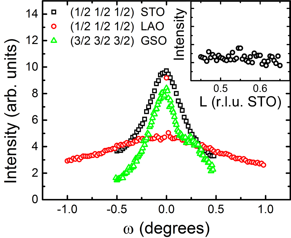
A broad survey of half-order diffraction peaks were measured to determine the pattern of octahedral rotations in the films. We first present measurements at conditions. These peaks arise from -site displacements with minimal intensity contribution from octahedral rotations.Glazer (1975) Figure 3 displays scans, as commonly referred to as rocking curves, through regions of reciprocal space for EuFeO3 films on STO, LAO and GSO, which all exhibit peaks. The presence of these peaks is consistent with the presence of -site displacements in the -type structure. In contrast, a 45 u.c. thick LaNiO3 film, shown inset of Fig. 3, does not exhibit a ( ) peak as expected for a -type perovskite lacking -site displacements. The broad and intense ( ) peak from the LSAT substrateSang et al. (2015) prevented measurement of the film peak at this condition for the EuFeO3/LSAT sample.
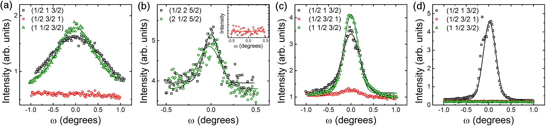
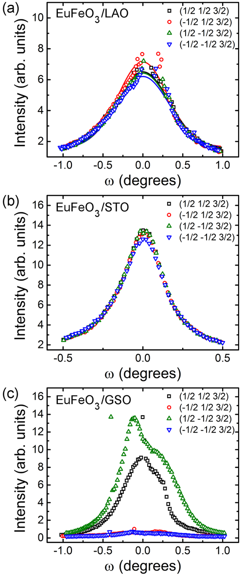
We next move to Bragg conditions in which one of the reciprocal lattice positions is an integer and the other two are unequal half-order positions, for example ( 1 ) or ( 2 ) where is an integer and . Figure 4 shows a series of three peaks in which either H, K, or L is an integer, and the total momentum transfer, q, is kept approximately constant. These peaks are present only when the integer reciprocal lattice variable is parallel to the real space direction of the in-phase rotation axis.Glazer (1975) For example, an pattern produces a ( 1) peak. The A-site displacements perpendicular to the direction of the in-phase rotation also contribute intensity to these peaks. Therefore, the presence of a ( 1)-type peak allows for the orientation of the in-phase rotation axis to be determined. For the films on LAO [Fig. 4(a)] and on LSAT [Fig. 4(b)], peaks with an integer in either or are observed, while peaks with an integer value are absent. Figure 4(a) shows a series of (1 )-type peaks for the EuFeO3/LAO sample. While the ( 1 ) and (1 ) have approximately equal intensity, no intensity is measured at the ( 1). Similar data is obtained from EuFeO3/LSAT, shown in Fig. 4(b), where a larger value of is used to better separate the film and substrate peaks. For the EuFeO3/STO film, shown in Fig. 4(c), the majority of the film takes a structure of or , with only a small fraction (4%) of the film exhibiting , as has previously been reported.Choquette et al. (2015)
In contrast, this multi-domain trend is not observed in the EuFeO3/GSO film. Instead, the film exhibits a uniform pattern, which matches that of the GSO substrate. As shown in Fig. 4(d), only the ( 1 ) peak is present and both the (1 ) and ( 1) peaks are absent. The ( 1 ) peak is asymmetric due to some contribution from the substrate in the scan. scans through these three regions of reciprocal space are presented as supplemental materials (Fig. S1).not
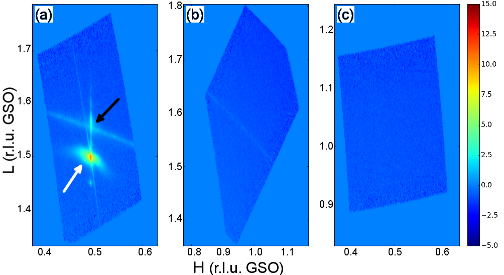
Reciprocal space maps measured near these same set of peaks further demonstrate that the film rotation behavior is dependent on that of the substrate. For the film on GSO, peaks at ( 1 ) from both the substrate and film can be seen in Fig. 5(a), with the white and black arrows highlighting the substrate and film peak, respectively. There is no intensity from either the substrate or film at the (1 ) and ( 1) conditions [Fig. 5(b,c)], consistent with a uniform pattern in both the substrate and film.
The { } series of peaks, shown in Fig. 6, provides additional evidence for the presence of mixed and patterns on LAO and STO, and uniform orientation on GSO. These peaks arise from out-of-phase rotations within the plane of the film ()Glazer (1975) and from -site displacements within the plane perpendicular to the rotation axis. Therefore, the presence of these peaks indicates that the EuFeO3/LAO and EuFeO3/STO films are not but instead contain regions of both and patterns. This is consistent with previous scanning transmission electron microscopy results obtained from an EuFeO3/STO film in which -type rotations were observed with the in-phase axis lying along different pseudocubic directions.Choquette et al. (2015)
Additionally, within a given rotation pattern, different rotational domains can arise. Each domain is defined by how the closest octahedron to the origin rotates (clockwise or counterclockwise) about each axis, which in turn dictates the displacement direction of the oxygen atoms within that rotation pattern. To probe these rotational domains, symmetrically equivalent half-order peaks with a fixed are measured.May et al. (2010) For the film on STO, we find that the intensity of the four { } peaks are equal, indicating an equal population of the rotational domains as would be expected for growth on a cubic substrate. Similar data is obtained from the EuFeO3/LAO sample, indicating that the rotational domains from LAO, which has an pattern, are not transferred into the film due to the symmetry mismatch at the interface. scans through these { } peaks are shown in the supplemental materials (Fig. S2). This data clearly demonstrates that the rotational domain populations are not equal in the LAO substrate in contrast to the EuFeO3 film, providing further evidence that the LAO is not imprinting rotational information into the film beyond the effect of strain. In contrast, the ( ) and ( - ) peaks are significantly more intense than the (- ) and (- - ) peaks in the EuFeO3 film on GSO. As shown in supplemental Fig. S3, the same trend in peak intensities is found in the GSO substrate. This result indicates that not only is the rotation pattern imprinted from the GSO substrate, but the rotational domains within that pattern are also transferred from the substrate to film.
IV Other -type Perovskites
IV.1 Films on non- substrates
Based on the purely geometric considerations described earlier in the text, one would expect that the in-phase rotation axis in -type perovskite films on cubic substrates would depend on the epitaxial strain state. A mixed and rotational pattern would be expected for compressive strain, putting the shorter pseudocubic in-phase axis in the plane of the film thereby minimizing strain along one of the in-plane directions. Under tensile strain, the lattice mismatch can be minimized by orienting the axis along the growth direction leading to an pattern. Indeed, this strain dependence of the in-phase axis has been predicted with density functional theory. For example, calculations of LaMnO3 and CaTiO3 reveal the pattern to be favorable under compressive strain and under tensile strain of less than 1 % and 1.5 %, respectively.Eklund et al. (2009); Lee et al. (2013) Similarly, the pattern was predicted to minimize energy in LaVO3 in compressive strain.Sclauzero and Ederer (2015) Under tensile strain above these values, the pattern becomes the lower energy structure. However, the energy differences between the two structural variants can be small; for example, first-principles calculations of strained LaVO3 and many rare earth ferrites revealed minimal energetic preference between and structures under tensile strain.Sclauzero and Ederer (2015); Zhao et al. (2014)
Our observation of an rotation pattern is consistent with previous experimental studies of epitaxial perovskites compressively strained to a non- substrate, including SrRuO3/STO,Chang et al. (2011); Lu et al. (2013); Vailionis et al. (2008); Ziese et al. (2010) Pr0.7Sr0.3MnO3/LAO,Mercey et al. (2000) LaVO3/STO,Rotella et al. (2012) LaFeO3/STO,Seo et al. (2008) GdTiO3/STO/LSAT,Zhang et al. (2013) GdTiO3/SrLaGaO4,Grisolia et al. (2014) Pr0.5Ca0.5MnO3/LAO,Haghiri-Gosnet et al. (2000) and La0.9Sr0.1MnO3/STO.Vigliante et al. (2001) The same structural variant has been reported in some films under small magnitudes of tensile strain, such as CaRuO3/LSAT (0.55 % tensile)Proffit et al. (2008) and PrVO3/STO (0.5 % tensile).Copie et al. (2013) In many of these studies, a mixture of and patterns was observed.Rotella et al. (2012); Seo et al. (2008); Mercey et al. (2000); Proffit et al. (2008); Copie et al. (2013)
There have also been reports of the pattern in films under tensile strain, especially in heterojunctions with larger than a 1 % lattice mismatch. These studies include Pr0.5Ca0.5MnO3/STO (2.3 % tensile),Prellier et al. (2000) NdNiO3/STO (2.6 % tensile),Tung et al. (2013) and La0.7Ca0.3MnO3/STO (1 % tensile).de Andrés et al. (2003) A mixture of all three orientations was reported in CaMnO3/LAO (2.3 % tensile).Günter et al. (2012)
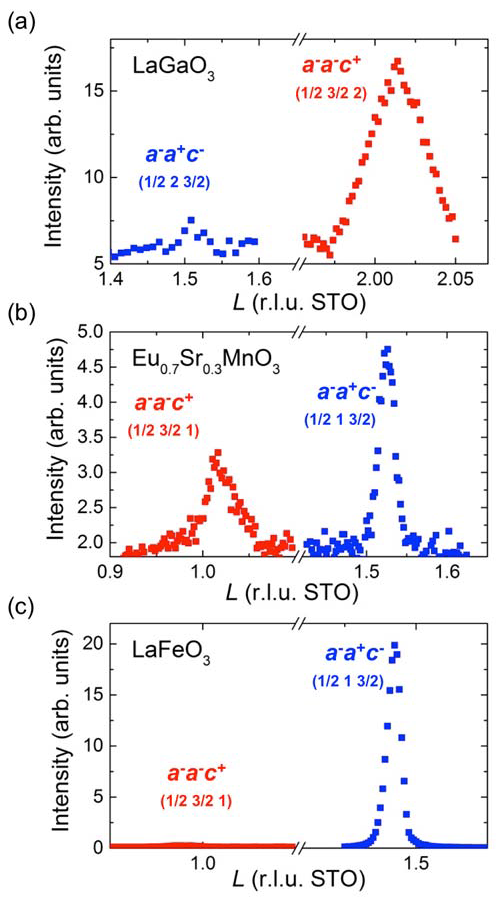
To gain further insight into the in-phase axis orientation in films under moderate tensile strain (between 0 - 2 %), we have measured the half-order peaks from LaGaO3/STO (0.5 % tensile) and Eu0.7Sr0.3MnO3/STO (1.5 % tensile). A survey of the half-order peaks indicate that both films retain the -type rotation pattern that is found in bulk compounds. As shown in Fig. 7(a), the LaGaO3 film is predominately oriented, which accounts for 94 % of the sample volume compared to 6 % for and domains as determined from intensity analysis of the half-order peaks. In contrast, the Eu0.7Sr0.3MnO3 film is comprised of 65 % and domains and 35 % domains, based on the half-order peaks shown in Fig. 7(b). Finally, Fig. 7(c) shows half-order peaks measured from LaFeO3/STO (-0.8 % compressive strain) revealing over 99 % of the film volume consists of and domains as expected for the film under compressive strain.
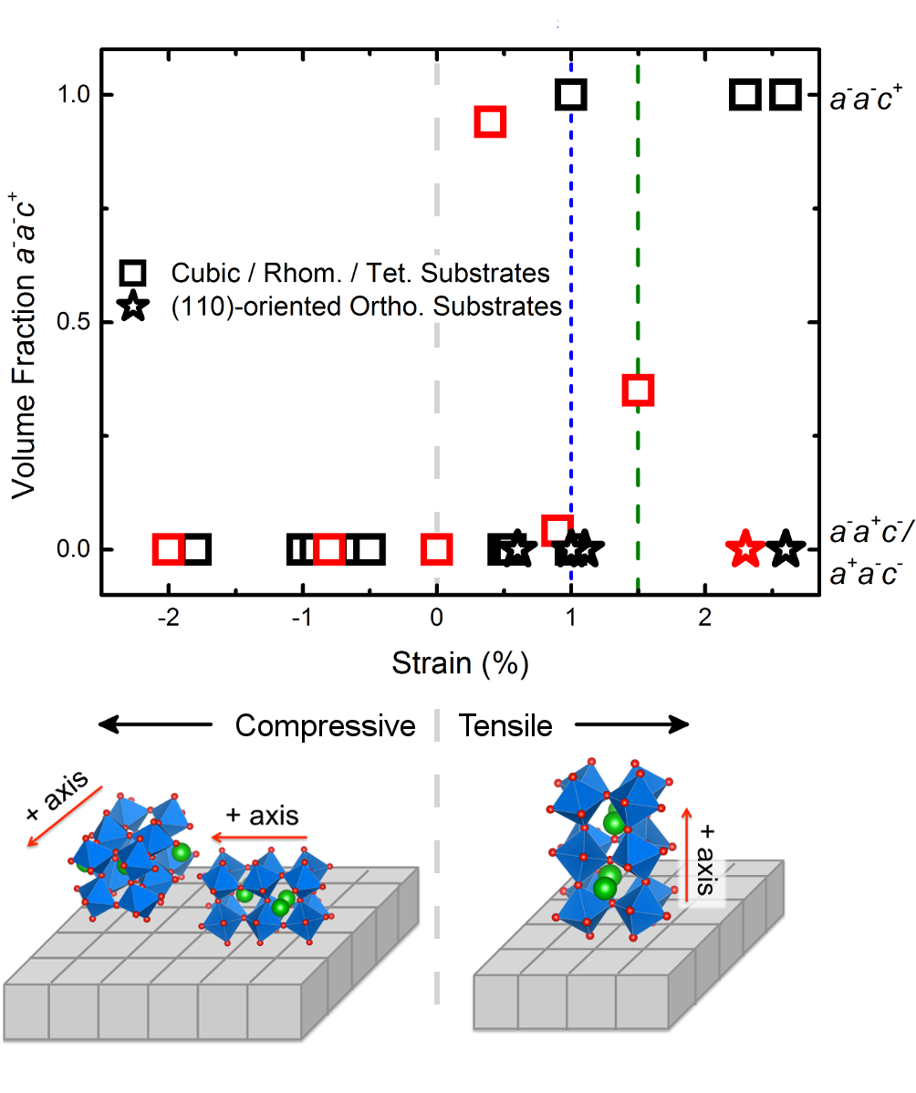
We compile our experimental results with those previously reported from both experiment and density functional theory in Fig. 8 to provide a comprehensive view of how the in-phase rotation axis responds to strain in films. From these results, three main conclusions can be drawn regarding the structural orientation of films on non- substrates. First, compressive strain leads to and/or structures. Second, large magnitudes of tensile strain ( %) promote structures. Finally, under moderate values of tensile strain (0 - 2 %) films can exhibit any of the three in-phase orientations and in many cases considerable volume fractions of all three orientations. Within this strain range, it remains an open question regarding what factors, such as material chemistry or distances found in the bulk structure, determine the rotation pattern orientation of films. A table containing sample compositions and references for the data presented in Fig. 8 is given in the supplemental materials.
IV.2 Films on substrates
As discussed in the introduction, design strategies for realizing hybrid improper ferroelectrics and polar metals in short-period superlattices rely on the -site ordering along the same direction as the in-phase rotation axis. This requires that the superlattices exhibit the structure. Based on Fig. 8, it is clear that such superlattices, when grown on cubic or rhombohedral substrates, must be under significant tensile strain to realize the correct orientation. However, the substrates most commonly used to induce large values of tensile strain are the rare earth scandates,Schlom et al. (2014) such as DyScO3 and GSO, compounds that exhibit the structure.Liferovich and Mitchell (2004) In films grown on these substrates, the structural coupling between the film and substrate leads to an imprinting of the substrate in-phase axis orientation into the film. This imprinting effect is observed in the EuFeO3/GSO films described here, and has also been reported in other papers detailing heteroepitaxial growth of -type films under tensile strain on -type substrates.Proffit et al. (2008); Kan et al. (2013); Aso et al. (2014b); Biegalski et al. (2015) These results from films on (110)-oriented substrates, in which the in-phase axis within the substrate is perpendicular to the growth direction, are also plotted in Fig. 8 illustrating the substrate-induced structural coupling effect. The primacy of substrate imprinting over strain in determining the in-phase rotation axis points to growth on (001)-oriented -type substrates as the most promising means to ensure behavior in perovskite films and superlattices.
Finally, it should be noted that we do not find an indirect imprinting effect on the in-phase axis from LAO, which exhibits an pattern, into -type films. Here one may expect that the octahedral connectivity can be better maintained if the film takes on the pattern that would retain coherence of the out-of-phase axes within the epitaxial plane at the interface. However, in both our experimental results and those previously reported, such behavior is not found. This suggests that direct imprinting of the in-phase axis from a substrate provides deterministic control of the structural orientation while indirect imprinting from a rhombohedral substrate does not.
V Conclusions
In summary, we report on the octahedral rotation patterns of strained EuFeO3 and other -type perovskite films. We observe a mixed and rotation pattern when grown on cubic or rhombohedral substrates, in EFO films under strain states ranging from 2% compressive to 0.9 % tensile. In contrast, EuFeO3 grown on orthorhombic GSO (110) exhibits a uniform orientation matching that of the substrate. To better understand the universality of this behavior, we have also measured LaGaO3/STO, LaFeO3/STO, and Eu0.7Sr0.3MnO3/STO and compiled previously reported structural data from -type films. The totality of the results indicates that compressive strain results in and patterns; moderate tensile strain can result in , , and/or structures; and large values of tensile strain ( 2 %) tends to favor . However, films under large tensile strain on -type substrates exhibit the same rotation pattern as that of the substrate, indicating that substrate imprinting of the in-phase axis offers a more robust means for deterministically controlling the rotation pattern compared to epitaxial strain. We anticipate that this work will enable more efficient experimental pursuits of recently predicted rotation-induced phenomena, such as hybrid improper ferroelectricity and non-centrosymmetric metals.
VI Acknowledgements
We thank Christian Schlepütz for assistance with the diffraction measurements. We are grateful to James Rondinelli and Craig Fennie for useful discussions. Work at Drexel was supported by the National Science Foundation (DMR-1151649). Use of the Advanced Photon Source was supported by the U. S. Department of Energy, Office of Science, Office of Basic Energy Sciences, under Contract No. DE-AC02-06CH11357.
References
- Schlom et al. (2008) D. G. Schlom, L.-Q. Chen, X. Pan, A. Schmehl, and M. A. Zurbuchen, J. Am. Ceram. Soc. 91, 2429 (2008).
- Hwang et al. (2012a) H. Hwang, Y. Iwasa, M. Kawasaki, B. Keimer, N. Nagaosa, and Y. Tokura, Nat. Mater. 11, 103 (2012a).
- Zubko et al. (2011) P. Zubko, S. Gariglio, M. Gabay, P. Ghosez, and J.-M. Triscone, Annu. Rev. Condens. Matter Phys. 2, 141 (2011).
- Bhattacharya and May (2014) A. Bhattacharya and S. J. May, Annu. Rev. Mater. Res. 44, 65 (2014).
- Bousquet et al. (2008) E. Bousquet, M. Dawber, N. Stucki, C. Lichtensteiger, P. Hermet, S. Gariglio, J. M. Triscone, and P. Ghosez, Nature 452, 732 (2008).
- Rondinelli et al. (2012) J. M. Rondinelli, S. J. May, and J. W. Freeland, MRS Bull. 37, 261 (2012).
- Benedek et al. (2012) N. A. Benedek, A. T. Mulder, and C. J. Fennie, J. Solid State Chem. 195, 11 (2012).
- Moon et al. (2014a) E. J. Moon, R. Colby, Q. Wang, E. Karapetrova, C. M. Schlepütz, M. R. Fitzsimmons, and S. J. May, Nat. Commun. 5, 5710 (2014a).
- Rondinelli and Fennie (2012) J. M. Rondinelli and C. J. Fennie, Adv. Mater. 24, 1961 (2012).
- Mulder et al. (2013) A. T. Mulder, N. A. Benedek, J. M. Rondinelli, and C. J. Fennie, Adv. Func. Mat. 23, 4810 (2013).
- Ghosh et al. (2015) S. Ghosh, H. Das, and C. J. Fennie, Phys. Rev. B 92, 184112 (2015).
- Benedek et al. (2015) N. A. Benedek, J. M. Rondinelli, H. Djani, P. Ghosez, and P. Lightfoot, Dalton Trans. 44, 10543 (2015).
- Puggioni and Rondinelli (2014) D. Puggioni and J. M. Rondinelli, Nat. Commun. 5, 3432 (2014).
- May et al. (2010) S. J. May, J.-W. Kim, J. M. Rondinelli, E. Karapetrova, N. A. Spaldin, A. Bhattacharya, and P. J. Ryan, Phys. Rev. B 82, 014110 (2010).
- Chang et al. (2011) S. H. Chang, Y. J. Chang, S. Y. Jang, D. W. Jeong, C. U. Jung, Y.-J. Kim, J.-S. Chung, and T. W. Noh, Phys. Rev. B 84, 104101 (2011).
- Rotella et al. (2012) H. Rotella, U. Lüders, P.-E. Janolin, V. H. Dao, D. Chateigner, R. Feyerherm, E. Dudzik, and W. Prellier, Phys. Rev. B 85, 184101 (2012).
- Johnson-Wilke et al. (2013) R. L. Johnson-Wilke, D. Marincel, S. Zhu, M. P. Warusawithana, A. Hatt, J. Sayre, K. T. Delaney, R. Engel-Herbert, C. M. Schlepütz, J.-W. Kim, et al., Phys. Rev. B 88, 174101 (2013).
- Lu et al. (2013) W. Lu, P. Yang, W. D. Song, G. M. Chow, and J. S. Chen, Phys. Rev. B 88, 214115 (2013).
- Fister et al. (2014) T. T. Fister, H. Zhou, Z. Luo, S. S. A. Seo, S. O. Hruszkewycz, D. L. Proffit, J. A. Eastman, P. H. Fuoss, P. M. Baldo, H. N. Lee, et al., APL Mater. 2, 021102 (2014).
- Zhang et al. (2014) B. Zhang, C.-J. Sun, P. Yang, W. Lu, B. L. Fisher, T. Venkatesan, S. M. Heald, J.-S. Chen, and G. M. Chow, Phys. Rev. B 89, 195140 (2014).
- Zhai et al. (2014) X. Zhai, L. Cheng, Y. Liu, C. M. Schlepütz, S. Dong, H. Li, X. Zhang, S. Chu, L. Zheng, J. Zhang, et al., Nat. Commun. 5, 4283 (2014).
- Biegalski et al. (2014) M. D. Biegalski, Y. Takamura, A. Mehta, Z. Gai, S. V. Kalinin, H. Ambaye, V. Lauter, D. Fong, S. T. Pantelides, Y. M. Kim, et al., Adv. Mater. Interfaces 1, 1400203 (2014).
- Kumah et al. (2014) D. P. Kumah, A. S. Disa, J. H. Ngai, H. Chen, A. Malashevich, J. W. Reiner, S. Ismail-Beigi, F. J. Walker, and C. H. Ahn, Adv. Mater. 26, 1935 (2014).
- Jia et al. (2009) C. L. Jia, S. B. Mi, M. Faley, U. Poppe, J. Schubert, and K. Urban, Phys. Rev. B 79, 081405 (2009).
- Borisevich et al. (2010) A. Y. Borisevich, H. J. Chang, M. Huijben, M. P. Oxley, S. Okamoto, M. K. Niranjan, J. D. Burton, E. Y. Tsymbal, Y. H. Chu, P. Yu, et al., Phys. Rev. Lett. 105, 087204 (2010).
- Aso et al. (2014a) R. Aso, D. Kan, Y. Shimakawa, and H. Kurata, Cryst. Growth Des. 14, 2128 (2014a).
- Hwang et al. (2012b) J. Hwang, J. Y. Zhang, J. Son, and S. Stemmer, Appl. Phys. Lett. 100, 191909 (2012b).
- Glazer (1975) A. M. Glazer, Acta Crystallogr. Sect. A 31, 756 (1975).
- Reaney and Woodward (2005) I. M. Reaney and D. I. Woodward, Acta Crystallogr. Sect. B 61, 387 (2005).
- Glazer (1972) A. M. Glazer, Acta Crystallogr. Sect. B 28, 3384 (1972).
- Woodward (1997a) P. M. Woodward, Acta Crystallogr. Sect. B 53, 32 (1997a).
- Thomas (1989) N. W. Thomas, Acta Crystallogr. Sect. B 45, 337 (1989).
- Woodward (1997b) P. M. Woodward, Acta Crystallogr. Sect. B 53, 44 (1997b).
- Copie et al. (2013) O. Copie, H. Rotella, P. Boullay, M. Morales, A. Pautrat, P.-E. Janolin, I. C. Infante, D. Pravathana, U. Lüders, and W. Prellier, J. Phys.: Condens. Matter 25, 492201 (2013).
- Proffit et al. (2008) D. L. Proffit, H. W. Jang, S. Lee, C. T. Nelson, X. Q. Pan, M. S. Rzchowski, and C. B. Eom, Appl. Phys. Lett. 93, 111912 (2008).
- Choi et al. (2010) K. J. Choi, S. H. Baek, H. W. Jang, L. J. Belenky, M. Lyubchenko, and C. B. Eom, Adv. Mater. 22, 759 (2010).
- Han et al. (2009) Y. Han, I. M. Reaney, D. S. Tinberg, and S. Trolier-McKinstry, Acta Crystallogr. Sect. B 65, 694 (2009).
- Kan et al. (2013) D. Kan, R. Aso, H. Kurata, and Y. Shimakawa, Adv. Func. Mater. 23, 1129 (2013).
- Marezio et al. (1970) M. Marezio, J. P. Remeika, and P. D. Dernier, Acta Crystallogr. Sect. B 26, 2008 (1970).
- Choquette et al. (2015) A. K. Choquette, R. Colby, E. J. Moon, C. M. Schlepütz, M. D. Scafetta, D. J. Keavney, and S. J. May, Cryst. Growth Des. 15, 1105 (2015).
- Scafetta et al. (2013) M. D. Scafetta, Y. J. Xie, M. Torres, J. E. Spanier, and S. J. May, Appl. Phys. Lett. 102, 081904 (2013).
- Moon et al. (2014b) E. J. Moon, D. J. Keavney, and S. J. May, Phys. Rev. Appl. 1, 054006 (2014b).
- Perna et al. (2010) P. Perna, D. Maccariello, M. Radovic, U. S. di Uccio, I. Pallecchi, M. Codda, D. Marre, C. Cantoni, J. Gazquez, M. Varela, et al., Appl. Phys. Lett. 97, 152111 (2010).
- Björck and Andersson (2007) M. Björck and G. Andersson, J. Appl. Crystallogr. 40, 1174 (2007).
- Falcon et al. (1997) H. Falcon, A. Goeta, G. Punte, and R. Carbonio, J. Solid State Chem. 133, 379 (1997).
- Vasylechko et al. (1999) L. Vasylechko, A. Matkovski, A. Suchocki, D. Savytskii, and I. Syvorotka, J. Alloys Comp. 286, 213 (1999).
- Komarek et al. (2007) A. C. Komarek, H. Roth, M. Cwik, W.-D. Stein, J. Baier, M. Kriener, F. Bourée, T. Lorenz, and M. Braden, Phys. Rev. B 75, 224402 (2007).
- Bordet et al. (1993) P. Bordet, C. Chaillout, M. Marezio, Q. Huang, A. Santoro, S.-W. Cheong, H. Takagi, C. Oglesby, and B. Batlogg, J. Solid State Chem. 106, 253 (1993).
- Tezuka et al. (1998) K. Tezuka, Y. Hinatsu, A. Nakamura, T. Inami, Y. Shimojo, and Y. Morii, J. Solid State Chem. 141, 404 (1998).
- Liu and Liebermann (1993) X. Liu and R. C. Liebermann, Phys. Chem. Miner. 20, 171 (1993).
- Takeda et al. (2000) T. Takeda, R. Kanno, Y. Kawamoto, M. Takano, S. Kawasaki, T. Kamiyama, and F. Izumi, Solid State Sci. 2, 673 (2000).
- Chmaissem et al. (2001) O. Chmaissem, B. Dabrowski, S. Kolesnik, J. Mais, D. E. Brown, R. Kruk, P. Prior, B. Pyles, and J. D. Jorgensen, Phys. Rev. B 64, 134412 (2001).
- Sang et al. (2015) X. Sang, E. D. Grimley, C. Niu, D. L. Irving, and J. M. LeBeau, Appl. Phys. Lett. 106, 061913 (2015).
- (54) See Supplementary Material at [URL will be inserted by publisher] for additional diffraction data and for references for data in Figure 8.
- Eklund et al. (2009) C.-J. Eklund, C. J. Fennie, and K. M. Rabe, Phys. Rev. B 79, 220101 (2009).
- Lee et al. (2013) J. H. Lee, K. T. Delaney, E. Bousquet, N. A. Spaldin, and K. M. Rabe, Phys. Rev. B 88, 174426 (2013).
- Sclauzero and Ederer (2015) G. Sclauzero and C. Ederer, Phys. Rev. B 92, 235112 (2015).
- Zhao et al. (2014) H. J. Zhao, Y. Yang, W. Ren, A.-J. Mao, X. M. Chen, and L. Bellaiche, J. Phys.: Condens. Matter 26, 472201 (2014).
- Vailionis et al. (2008) A. Vailionis, W. Siemons, and G. Koster, Appl. Phys. Lett. 93, 051909 (2008).
- Ziese et al. (2010) M. Ziese, I. Vrejoiu, and D. Hesse, Phys. Rev. B 81, 184418 (2010).
- Mercey et al. (2000) B. Mercey, J. Wolfman, W. Prellier, M. Hervieu, C. Simon, and B. Raveau, Chem. Mater. 12, 2858 (2000).
- Seo et al. (2008) J. W. Seo, E. E. Fullerton, F. Nolting, A. Scholl, J. Fompeyrine, and J.-P. Locquet, J. Phys.: Condens. Matter 20, 264014 (2008).
- Zhang et al. (2013) J. Y. Zhang, J. Hwang, S. Raghavan, and S. Stemmer, Phys. Rev. Lett. 110, 256401 (2013).
- Grisolia et al. (2014) M. N. Grisolia, F. Y. Bruno, D. Sando, H. J. Zhao, E. Jacquet, X. M. Chen, L. Bellaiche, A. Barthélémy, and M. Bibes, Appl. Phys. Lett. 105, 172402 (2014).
- Haghiri-Gosnet et al. (2000) A. M. Haghiri-Gosnet, M. Hervieu, C. Simon, B. Mercey, and B. Raveau, J. Appl. Phys. 88, 3545 (2000).
- Vigliante et al. (2001) A. Vigliante, U. Gebhardt, A. Rühm, P. Wochner, F. S. Razavi, and H. U. Habermeier, Europhys. Lett. 54, 619 (2001).
- Prellier et al. (2000) W. Prellier, A. M. Haghiri-Gosnet, B. Mercey, P. Lecoeur, M. Hervieu, C. Simon, and B. Raveau, Appl. Phys. Lett. 77, 1023 (2000).
- Tung et al. (2013) I. C. Tung, P. V. Balachandran, J. Liu, B. A. Gray, E. A. Karapetrova, J. H. Lee, J. Chakhalian, M. J. Bedzyk, J. M. Rondinelli, and J. W. Freeland, Phys. Rev. B 88, 205112 (2013).
- de Andrés et al. (2003) A. de Andrés, J. Rubio, G. Castro, S. Taboada, J. L. Martı́nez, and J. M. Colino, Appl. Phys. Lett. 83, 713 (2003).
- Günter et al. (2012) T. Günter, E. Bousquet, A. David, P. Boullay, P. Ghosez, W. Prellier, and M. Fiebig, Phys. Rev. B 85, 214120 (2012).
- Schlom et al. (2014) D. G. Schlom, L.-Q. Chen, C. J. Fennie, V. Gopalan, D. A. Muller, X. Pan, R. Ramesh, and R. Uecker, MRS Bull. 39, 118 (2014).
- Liferovich and Mitchell (2004) R. P. Liferovich and R. H. Mitchell, J. Solid State Chem. 177, 2188 (2004).
- Aso et al. (2014b) R. Aso, D. Kan, Y. Fujiyoshi, Y. Shimakawa, and H. Kurata, Cryst. Growth Des. 14, 6478 (2014b).
- Biegalski et al. (2015) M. D. Biegalski, L. Qiao, Y. Gu, A. Mehta, Q. He, Y. Takamura, A. Borisevich, and L.-Q. Chen, Appl. Phys. Lett. 106, 162904 (2015).