Control of Exciton Valley Coherence in Transition Metal Dichalcogenide Monolayers
Abstract
The direct gap interband transitions in transition metal dichalcogenides monolayers are governed by chiral optical selection rules. Determined by laser helicity, optical transitions in either the or valley in momentum space are induced. Linearly polarized laser excitation prepares a coherent superposition of valley states. Here we demonstrate the control of the exciton valley coherence in monolayer WSe2 by tuning the applied magnetic field perpendicular to the monolayer plane. We show rotation of this coherent superposition of valley states by angles as large as 30 degrees in applied fields up to 9 T. This exciton valley coherence control on ps time scale could be an important step towards complete control of qubits based on the valley degree of freedom.
Atomically thin layers of Van der Waals bonded materials open up new possibilities for fundamental physics in 2D systems and for new applications Geim and Grigorieva (2013); Novoselov et al. (2005); Castellanos-Gomez (2016). Here the group-VI Transition metal dichalcogenides (TMDCs) of the form MX2, where M= and X= stand out: These indirect semiconductors in bulk form become direct semiconductors when thinned down to one monolayer (ML) Mak et al. (2010); Splendiani et al. (2010); Eda et al. (2011); Zhao et al. (2013); Amani et al. (2015); Sundaram et al. (2013); Pospischil et al. (2014); Withers et al. (2015); Conley et al. (2013).
The valence and conduction band extrema of a ML reside at the point of the Brillouin zone. Current research interest is stimulated by their strong light-matter interaction and the possibility to use the valley index as an information carrier and for exciting fundamental physics experiments Xiao et al. (2012); Xu et al. (2014); Mak et al. (2014); Yang et al. (2015); Hao et al. (2016); Mak and Shan (2016).
Due to the reduction of dielectric screening and the large effective carrier masses in TMDCs monolayers the light-matter interaction is dominated by the excitons (Coulomb bound electron-hole pairs), with binding energies up to several hundred meV Chernikov et al. (2014); Zhu et al. (2015); Ugeda et al. (2014); Wang et al. (2015a); He et al. (2014); Hanbicki et al. (2015); Ye et al. (2014). Using polarized excitation, the optical excitation of carriers in the () valley results in formation of an exciton with pseudo-spin () Mak et al. (2012); Zeng et al. (2012); Cao et al. (2012).
A basic requirement for quantum information processing experiments using the valley degree of freedom is the ability to completely control the state of a single qubit, as demonstrated for electron spins in quantum dots Press et al. (2008).
A universal single qubit gate is realized by a rotation of a single spin, for example, by any angle about an arbitrary axis.
One strategy for qubit manipulation is to use picosecond or femtosecond laser pulses, permitting an arbitrary rotation to be completed within one spin precession period.
Here a first important step was the demonstration in ML WSe2 of the superposition of two valley states.
This is achieved optically by linearly polarized excitation, which results in strongly linearly polarized neutral exciton (X0) emission Jones et al. (2013); Wang et al. (2014, 2015b). Contrary to coherent exciton manipulation in the model system of GaAs quantum well excitons Bar-Ad and Bar-Joseph (1991); Amand et al. (1997); Marie et al. (1997), here in ML TMDCs the optical excitation can be at much higher energy than the transition Wang et al. (2015b) i.e. strictly resonant excitation/detection of the coherent exciton states is not required. Despite these favorable conditions, so far a demonstration of exciton valley coherence control is lacking.
In this work we demonstrate that the neutral exciton valley coherence in monolayer WSe2 can be controlled by an external magnetic field applied vertically to the sample plane. In the absence of external fields, the electronic states related by time reversal in the and valleys are degenerate. The valley exciton degeneracy can be lifted by a longitudinal magnetic field Li et al. (2014); Srivastava et al. (2015); MacNeill et al. (2015); Aivazian et al. (2015); Arora et al. (2016); Wang et al. (2015c) or the optical Stark effect Kim et al. (2014); Sie et al. (2015).
In our experiment the external magnetic field lifts the valley degeneracy and results in a change of the oscillation frequency of the coherent superposition of valley states. This corresponds to a rotation of valley coherence (i.e. the exciton pseudo-spin) and we clearly measure this rotation in our experiments with angles up to 30 degrees at T. This type of quantum beat process was observed initially in atoms and molecular systems Shoemaker and Hopf (1974) and then intensely investigated for excitons in low dimensional GaAs structures by time-resolved optical techniques Bar-Ad and Bar-Joseph (1991); Amand et al. (1997); Marie et al. (1997). Whereas in other material systems coherent manipulation is necessarily a 2 pulse experiment to read and write the quantum state, we show here that in ML TMDCs these experiments can be carried out with simple cw excitation and photo-luminescence (PL) detection.
Samples and Experimental Set-up.—
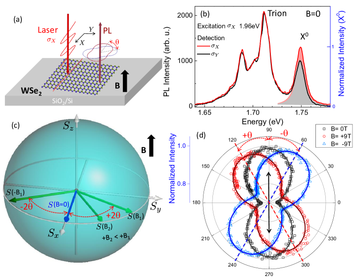
The WSe2 ML flakes are prepared by micro-mechanical cleavage of a bulk crystal (from 2D Semiconductors) on SiO2/Si substrates. The experiments are carried at T=4 K and in magnetic fields up to 9 T in Faraday configuration in a confocal microscope as shown in Fig. 1a. The excitation/detection spot diameter is m, i.e. smaller than the typical ML diameter. The WSe2 ML is excited by a linearly polarized () continuous wave He-Ne laser (1.96 eV) to generate valley coherence (i.e. optical alignment of excitons Meier and Zakharchenya (1984)). Our target is to detect the neutral exciton X0 valley coherence in the linear basis in PL emission, see Fig. 1b. A liquid crystal based linear polarization rotator is applied in the detection path, to detect a possible rotation of the linear basis of the PL signal with respect to the initial linear excitation basis. This approach avoids any macroscopic mechanical movement during the measurement and gives an accurate map of the angle dependent PL intensity as schematically illustrated in Fig. 1a, the full data set is plotted in Fig. 1d. The PL signal is dispersed in a spectrometer and detected with a Si-CCD camera. Based on these time integrated PL results we can then generate the polar plot of the intensity of the X0 emission for different magnetic field values and then monitor the rotation of the valley coherence by an angle as illustrated in Fig. 1a. Faraday effects of the optical set-up in applied fields have been systematically calibrated for plotting the valley coherence rotation angle.
Results and Discussion.—
Our experiment consists of 3 steps: First we want to optically initialize a coherent superposition of exciton states. Second, during the exciton lifetime we want to rotate the exciton pseudo-spin. Third, we read out the final state after rotation. This 3 step experiment will of course only be successful if the coherence time is sufficiently long compared to the read-out time Hao et al. (2016).
In the experiment we monitor the neutral exciton X0 PL emission, which is linearly polarized along the same axis as the excitation laser. This corresponds to successful valley coherence generation Jones et al. (2013), as shown in Fig. 1b.
The linear polarization of X0 measured along the initial excitation direction (i.e. the laser polarization axis) is around 15%. In contrast, both trion and lower energy emission peaks present no linear polarization as reported commonly for ML WSe2 Jones et al. (2013); Wang et al. (2014). In analogy to spin, the average of this coherent superposition of valley states can be represented by a vector that lies on the equator of a Bloch sphere as illustrated in Fig. 1c.
The north (south ) pole on the Bloch sphere corresponds to a () exciton states, which can be optically generated by () optical excitation. The equator corresponds to an X0 in-plane valley pseudo-spin, coherent superposition of and with different phases.
Radiative recombination of the X0 results in photon emission. Importantly, the exciton’s pseudo-spin direction in the equator will determine the linear polarization of the photon. In the absence of external fields, the linear polarization basis of the emitted photon is the same as the excitation laser i.e. no pseudo-spin rotation occurs during the short PL emission time ps Palummo et al. (2015); Robert et al. (2016); Pöllmann et al. (2015); Korn et al. (2011) as the main axis of the polar plot Fig. 1d (black squares) is aligned along the laser polarization direction.
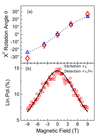
In order to rotate the exciton spin, we now apply a magnetic field which lifts valley degeneracy. At the exciton valley coherence state after a linearly polarized excitation along the direction evolves with time as , where are the exciton spin states, the energy difference between the two valleys with the Bohr magneton and the X0 Lande -factor. The PL emission time in ML WSe2 is of the order of ps. It should therefore be possible to read out the final state after rotation within the first precession period by simply analysing the linear polarization basis of the X0 PL. Clear rotations of the linear polarization axis are observed in Fig. 1d for B=-9 T and also B=+9 T. At B=+9 T we measure a rotation of degrees with respect to the initial laser excitation polarization. Changing from +9 to -9 T, we observe that also changes sign while keeping the same amplitude, as the exciton pseudo-spin rotation now occurs in the opposite direction. These trends are confirmed for the intermediate values at B= T as plotted in Fig. 2a. Very similar data has been obtained for other ML WSe2 samples.
The solid lines in Fig.1d are fits using , where is the detection angle and represents the X0 linear polarization angle. Experimentally, it is clear from Figs. 1d and 2a that we can control the rotation of the linearly polarized exciton emission with respect to the initial laser excitation axis.
Now we give a very simple interpretation of the experiments in terms of rotating a superposition of exciton and states originating from exciton pseudo-spins: In principle, in a finite magnetic field applied perpendicular to the ML, the valley coherence has a nonzero precession frequency due to the energy difference between the and exciton states. A certain time after the initialization of the valley coherence state, it will evolve to a new position in the equator of the Bloch sphere as shown in Fig. 1c by the green arrows labelled with . With a different magnetic field B2 the final position of the valley coherence state can be selectively adjusted to a different rotation angle. Through the fits used in Fig. 1d, we deduce the magnetic field dependence of the rotation angle, shown in Fig. 2a with open red circles. In our simple approach we assume that the valley coherence generation rate does not change as a function of the applied magnetic field. This scenario is very similar to the standard Hanle effect Dyakonov (2008): the initial pseudo-spin generated along the direction (laser polarization axis) precesses around the magnetic field applied in the direction (perpendicular to the ML plane) at frequency . For linear excitation the generated pseudo-spin component . In stationary conditions the pseudo-spin state in-plane components in an applied magnetic field B can be expressed as:
| (1) |
| (2) |
where, , is the exciton lifetime, is the exciton valley coherence time. The pseudo-spin rotates by an angle , where tan. Therefore we can deduce the X0 PL rotation angle , as plotted in Fig. 2a (gray dashed line) using and . The values calculated at the magnetic field values used in our experiment are plotted as blue open triangles for comparison with the data. This simple model yields excellent agreement with our experimental results. The factor of X0 in ML WSe2 is extracted from circularly resolved magneto PL results Wang et al. (2015c), which is also similar to other reports for this material Srivastava et al. (2015); Mitioglu et al. (2015). We therefore extract a value of of around ps. Assuming an exciton lifetime of ps Robert et al. (2016) we can roughly estimate a valley coherence time of around 0.45 ps. This value is of the same order of magnitude as the measured valley coherence time of a highly crystalline CVD-grown WSe2 sample on sapphire substrate Hao et al. (2016).
We have shown that the linear polarization axis of the X0 PL rotates as a function of the applied magnetic field. Using the linear polarization basis of the laser also for detection of the PL at , would lead therefore to a lowering of the observed linear polarization. This is exactly what has been reported recently for ML WSe2 Aivazian et al. (2015); Wang et al. (2015c).
For the same sample investigated first in Figs. 1d and 2a (where we rotate the detection basis) we show in Fig. 2b the linear polarization degree of the X0 PL for a fixed linear basis (parallel to the excitation laser). The linear polarization degree of X0 drops from 15% at to 7% at 9 T. In our very simple description without considering the magnetic field dependence of the valley coherence generation rate, this linear polarization should be directly deduced by equation (1). In Fig. 2b (fixed detection basis) we generate the solid line with the same parameters as used in Fig. 2a (optimized detection basis), the agreement of the simple model with the experimental results is remarkable. This close fit indicates that changes of the valley coherence generation rate as a function of magnetic field are negligible in our measurement.
Conclusions and Perspectives.—
Following the demonstration of optically generated valley polarization and valley coherence in the literature, we go a step further by demonstrating the coherent manipulation of valley states. This corresponds to a rotation of the exciton spin around the equator of the Bloch sphere, where the rotation angle is set by the value of the applied magnetic field. This is an important step towards the generation of an arbitrary exciton state in order to reach complete control of exciton states. To access states on the Bloch sphere away from the equator (i.e. ) elliptically polarized light can be used for pseudo-spin initialization. In this case the influence of the long-range electron-hole Coulomb exchange interaction on the exciton pseudo-spin evolution in applied fields needs to be investigated in the future Maialle et al. (1993); Yu et al. (2014); Yu and Wu (2014); Glazov et al. (2014).
The clearest signatures of valley coherence in MX2 compounds have been observed in ML WSe2, even using non-resonant excitation Jones et al. (2013); Hao et al. (2016); Wang et al. (2015b). Another high quality material with spectrally narrow exciton emission is ML MoSe2, but here very close to resonant excitation is necessary to observe any valley polarization Kioseoglou et al. (2016); Wang et al. (2015d). Only very recently optically generated valley coherence has been observed in PL of acid treated ML MoS2 Cadiz et al. (2016), providing another interesting sample system for valley coherence experiments.
Acknowledgements.— We thank ERC Grant No. 306719 and ANR MoS2ValleyControl for financial support. X.M. also acknowledges the Institut Universitaire de France. F.C and P. R thank the grant NEXT No ANR-10-LABX-0037 in the framework of the Programme des Investissements d’Avenir”. B. L. acknowledges the support by the National Science Foundation of
China Grant No. 11574357 and the National Basic Research Program of
China Grant No. 2015CB921001. We acknowledge very fruitful discussions with Prof. Juren Shi at early stages of the project.
References
- Geim and Grigorieva (2013) A. K. Geim and I. V. Grigorieva, Nature 499, 419 (2013).
- Novoselov et al. (2005) K. S. Novoselov, D. Jiang, F. Schedin, T. J. Booth, V. V. Khotkevich, S. V. Morozov, and A. K. Geim, Proc. Natl Acad. Sci. USA 102, 10451 (2005).
- Castellanos-Gomez (2016) A. Castellanos-Gomez, Nature Photonics 10, 202 (2016).
- Mak et al. (2010) K. F. Mak, C. Lee, J. Hone, J. Shan, and T. F. Heinz, Phys. Rev. Lett. 105, 136805 (2010).
- Splendiani et al. (2010) A. Splendiani, L. Sun, Y. Zhang, T. Li, J. Kim, C.-Y. Chim, G. Galli, and F. Wang, Nano Letters 10, 1271 (2010).
- Zhao et al. (2013) W. Zhao, Z. Ghorannevis, L. Chu, M. Toh, C. Kloc, P.-H. Tan, and G. Eda, ACS Nano 7, 791 (2013).
- Eda et al. (2011) G. Eda, H. Yamaguchi, D. Voiry, T. Fujita, M. Chen, and M. Chhowalla, Nano Letters 11, 5111 (2011).
- Amani et al. (2015) M. Amani, D.-H. Lien, D. Kiriya, J. Xiao, A. Azcatl, J. Noh, S. R. Madhvapathy, R. Addou, K. Santosh, M. Dubey, et al., Science 350, 1065 (2015).
- Sundaram et al. (2013) R. S. Sundaram, M. Engel, A. Lombardo, R. Krupke, A. C. Ferrari, P. Avouris, and M. Steiner, Nano Letters 13, 1416 (2013).
- Pospischil et al. (2014) A. Pospischil, M. M. Furchi, and T. Mueller, Nature nanotechnology 9, 257 (2014).
- Withers et al. (2015) F. Withers, O. D. Pozo-Zamudio, S. Schwarz, S. Dufferwiel, P. M. Walker, T. Godde, A. P. Rooney, A. Gholinia, C. R. Woods, P. Blake, et al., Nano Letters 15, 8223 (2015).
- Conley et al. (2013) H. J. Conley, B. Wang, J. I. Ziegler, R. F. Haglund Jr, S. T. Pantelides, and K. I. Bolotin, Nano letters 13, 3626 (2013).
- Xiao et al. (2012) D. Xiao, G.-B. Liu, W. Feng, X. Xu, and W. Yao, Phys. Rev. Lett. 108, 196802 (2012).
- Xu et al. (2014) X. Xu, D. Xiao, T. F. Heinz, and W. Yao, Nature Physics 10, 343 (2014).
- Mak and Shan (2016) K. F. Mak and J. Shan, Nature Photonics 10, 216 (2016).
- Hao et al. (2016) K. Hao, G. Moody, F. Wu, C. K. Dass, L. Xu, C.-H. Chen, M.-Y. Li, L.-J. Li, A. H. MacDonald, and X. Li, Nature Physics doi:10.1038/nphys3674 (2016).
- Mak et al. (2014) K. F. Mak, K. L. McGill, J. Park, and P. L. McEuen, Science 344, 1489 (2014).
- Yang et al. (2015) L. Yang, N. A. Sinitsyn, W. Chen, J. Yuan, J. Zhang, J. Lou, and S. A. Crooker, Nature Physics 11, 830 (2015).
- Chernikov et al. (2014) A. Chernikov, T. C. Berkelbach, H. M. Hill, A. Rigosi, Y. Li, O. B. Aslan, D. R. Reichman, M. S. Hybertsen, and T. F. Heinz, Phys. Rev. Lett. 113, 076802 (2014).
- Zhu et al. (2015) B. Zhu, X. Chen, and X. Cui, Scientific Reports 5, 9218 (2015).
- Ugeda et al. (2014) M. M. Ugeda, A. J. Bradley, S.-F. Shi, F. H. da Jornada, Y. Zhang, D. Y. Qiu, S.-K. Mo, Z. Hussain, Z.-X. Shen, F. Wang, et al., Nature Materials 13, 1091 (2014).
- Wang et al. (2015a) G. Wang, X. Marie, I. Gerber, T. Amand, D. Lagarde, L. Bouet, M. Vidal, A. Balocchi, and B. Urbaszek, Phys. Rev. Lett. 114, 097403 (2015a).
- He et al. (2014) K. He, N. Kumar, L. Zhao, Z. Wang, K. F. Mak, H. Zhao, and J. Shan, Phys. Rev. Lett. 113, 026803 (2014).
- Hanbicki et al. (2015) A. Hanbicki, M. Currie, G. Kioseoglou, A. Friedman, and B. Jonker, Solid State Communications 203, 16 (2015).
- Ye et al. (2014) Z. Ye, T. Cao, K. O’Brien, H. Zhu, X. Yin, Y. Wang, S. G. Louie, and X. Zhang, Nature 513, 214 (2014).
- Mak et al. (2012) K. F. Mak, K. He, J. Shan, and T. F. Heinz, Nat. Nanotechnol. 7, 494 (2012).
- Zeng et al. (2012) H. Zeng, J. Dai, W. Yao, D. Xiao, and X. Cui, Nat. Nanotechnol. 7, 490 (2012).
- Cao et al. (2012) T. Cao, G. Wang, W. Han, H. Ye, C. Zhu, J. Shi, Q. Niu, P. Tan, E. Wang, B. Liu, et al., Nature Communications 3, 887 (2012).
- Press et al. (2008) D. Press, T. D. Ladd, B. Zhang, and Y. Yamamoto, Nature 456, 218 (2008).
- Wang et al. (2014) G. Wang, L. Bouet, D. Lagarde, M. Vidal, A. Balocchi, T. Amand, X. Marie, and B. Urbaszek, Phys. Rev. B 90, 075413 (2014).
- Jones et al. (2013) A. M. Jones, H. Yu, N. J. Ghimire, S. Wu, G. Aivazian, J. S. Ross, B. Zhao, J. Yan, D. G. Mandrus, D. Xiao, et al., Nat. Nanotechnol. 8, 634 (2013).
- Wang et al. (2015b) G. Wang, M. M. Glazov, C. Robert, T. Amand, X. Marie, and B. Urbaszek, Phys. Rev. Lett. 115, 117401 (2015b).
- Bar-Ad and Bar-Joseph (1991) S. Bar-Ad and I. Bar-Joseph, Phys. Rev. Lett. 66, 2491 (1991).
- Amand et al. (1997) T. Amand, X. Marie, P. Le Jeune, M. Brousseau, D. Robart, J. Barrau, and R. Planel, Phys. Rev. Lett. 78, 1355 (1997).
- Marie et al. (1997) X. Marie, P. Le Jeune, T. Amand, M. Brousseau, J. Barrau, M. Paillard, and R. Planel, Phys. Rev. Lett. 79, 3222 (1997).
- Li et al. (2014) Y. Li, J. Ludwig, T. Low, A. Chernikov, X. Cui, G. Arefe, Y. D. Kim, A. M. van der Zande, A. Rigosi, H. M. Hill, et al., Phys. Rev. Lett. 113, 266804 (2014).
- Srivastava et al. (2015) A. Srivastava, M. Sidler, A. V. Allain, D. S. Lembke, A. Kis, and A. Imamoğlu, Nature Physics (2015).
- MacNeill et al. (2015) D. MacNeill, C. Heikes, K. F. Mak, Z. Anderson, A. Kormányos, V. Zólyomi, J. Park, and D. C. Ralph, Phys. Rev. Lett. 114, 037401 (2015).
- Aivazian et al. (2015) G. Aivazian, Z. Gong, A. M. Jones, R.-L. Chu, J. Yan, D. G. Mandrus, C. Zhang, D. Cobden, W. Yao, and X. Xu, Nature Physics 11, 148 (2015).
- Arora et al. (2016) A. Arora, R. Schmidt, R. Schneider, M. R. Molas, I. Breslavetz, M. Potemski, and R. Bratschitsch, Nano Letters 0, 10.1021/acs.nanolett.6b00748 (2016).
- Wang et al. (2015c) G. Wang, L. Bouet, M. M. Glazov, T. Amand, E. L. Ivchenko, E. Palleau, X. Marie, and B. Urbaszek, 2D Materials 2, 034002 (2015c).
- Kim et al. (2014) J. Kim, X. Hong, C. Jin, S.-F. Shi, C.-Y. S. Chang, M.-H. Chiu, L.-J. Li, and F. Wang, Science 346, 1205 (2014).
- Sie et al. (2015) E. J. Sie, J. W. McIver, Y.-H. Lee, L. Fu, J. Kong, and N. Gedik, Nature materials 14, 290 (2015).
- Shoemaker and Hopf (1974) R. L. Shoemaker and F. A. Hopf, Phys. Rev. Lett. 33, 1527 (1974).
- Meier and Zakharchenya (1984) F. Meier and B. Zakharchenya, Modern Problems in Condensed Matter Sciences (North-Holland, Amsterdam). 8 (1984).
- Palummo et al. (2015) M. Palummo, M. Bernardi, and J. C. Grossman, Nano Letters 15, 2794 (2015), pMID: 25798735.
- Robert et al. (2016) C. Robert, D. Lagarde, F. Cadiz, G. Wang, B. Lassagne, T. Amand, A. Balocchi, P. Renucci, S. Tongay, B. Urbaszek, et al., Phys. Rev. B 93, 205423 (2016).
- Pöllmann et al. (2015) C. Pöllmann, P. Steinleitner, U. Leierseder, P. Nagler, G. Plechinger, M. Porer, R. Bratschitsch, C. Schüller, T. Korn, and R. Huber, Nature materials 14, 889 (2015).
- Korn et al. (2011) T. Korn, S. Heydrich, M. Hirmer, J. Schmutzler, and C. Schüller, Applied Physics Letters 99, 102109 (2011).
- Dyakonov (2008) M. Dyakonov, Springer Series in Solid-State Science, Springer-Verlag Berlin 157 (2008).
- Mitioglu et al. (2015) A. Mitioglu, P. Plochocka, A. Granados del Aguila, P. Christianen, G. Deligeorgis, S. Anghel, L. Kulyuk, and D. Maude, Nano letters 15, 4387 (2015).
- Maialle et al. (1993) M. Z. Maialle, E. A. de Andrada e Silva, and L. J. Sham, Phys. Rev. B 47, 15776 (1993).
- Yu et al. (2014) H. Yu, G. Liu, P. Gong, X. Xu, and W. Yao, Nature Comms. 5, 3876 (2014).
- Yu and Wu (2014) T. Yu and M. W. Wu, Phys. Rev. B 89, 205303 (2014).
- Glazov et al. (2014) M. M. Glazov, T. Amand, X. Marie, D. Lagarde, L. Bouet, and B. Urbaszek, Phys. Rev. B 89, 201302 (2014).
- Kioseoglou et al. (2016) G. Kioseoglou, A. T. Hanbicki, M. Currie, A. L. Friedman, and B. T. Jonker, ArXiv e-prints (2016), eprint 1602.00640.
- Wang et al. (2015d) G. Wang, E. Palleau, T. Amand, S. Tongay, X. Marie, and B. Urbaszek, Applied Physics Letters 106, 112101 (2015d).
- Cadiz et al. (2016) F. Cadiz, S. Tricard, M. Gay, D. Lagarde, G. Wang, C. Robert, P. Renucci, B. Urbaszek, and X. Marie, ArXiv e-prints (2016), eprint 1604.05831.