Hierarchical Self-Assembly of Fractals with Signal-Passing Tiles
Abstract
In this paper, we present high-level overviews of tile-based self-assembling systems capable of producing complex, infinite, aperiodic structures known as discrete self-similar fractals. Fractals have a variety of interesting mathematical and structural properties, and by utilizing the bottom-up growth paradigm of self-assembly to create them we not only learn important techniques for building such complex structures, we also gain insight into how similar structural complexity arises in natural self-assembling systems. Our results fundamentally leverage hierarchical assembly processes, and use as our building blocks square “tile” components which are capable of activating and deactivating their binding “glues” a constant number of times each, based only on local interactions. We provide the first constructions capable of building arbitrary discrete self-similar fractals at scale factor 1, and many at temperature 1 (i.e. “non-cooperatively”), including the Sierpinski triangle.
1 Introduction
Fractal patterns have mathematically interesting characteristics, such as recursive self-similarity, and structural properties which lend naturally occurring fractal structures, such as branch patterns and circulatory systems, impressive abilities to efficiently maximize coverage, dissipate heat, etc. Such fractal patterns in nature tend to arise via local processes following relatively simple sets of rules, as forms of self-assembly. Because of this, and the complex aperiodic nature of fractals, they are a natural target of study during the development of artificial self-assembling systems. As one of the first mathematical abstractions of self-assembling systems, Winfree’s abstract Tile Assembly Model (aTAM) Winf98 has been the platform for several results showing the impossibility of self-assembling discrete self-similar fractals such as the Sierpinski triangle111In this paper we refer only to “strict” self-assembly, wherein a shape is made by placing tiles only within the domain of the shape, as opposed to “weak” self-assembly where a pattern representing the shape can be formed embedded within a framework of additional tiles.jSSADST and similar fractals TreeFractals , and also for designing systems which can approximate them jSSADST ; LutzShutters12 ; jSADSSF . In a more generalized model called the 2-Handed Assembly Model AGKS05g (2HAM, a.k.a. Hierarchical Assembly Model) which allows pairs of large assemblies to bind together, rather than being restricted to only single tile additions per step like the aTAM, the impossibility of self-assembling the Sierpinski triangle Versus has also been shown. In further generalizations allowing larger numbers of assemblies to combine in single steps MHAM shapes were shown to self-assemble as well one unscaled fractal, the Sierpinski carpet.
A more recently developed model of tile-based self-assembly, called the Signal-passing Tile Assembly Model (STAM) was developed in jSignals to model the behavior of DNA-based tiles capable of strand displacement reactions initiated during the binding of their glues which can then either activate or deactivate other glues on the same tile. Such signal-passing tiles have been experimentally demonstrated SignalTilesExperimental , and various theoretical results have demonstrated the power of systems using such tiles to efficiently simulate Turing machines jSignals , replicate patterns STAMPatternRep and shapes STAMshapes , and also to self-assemble the Sierpinski triangle at scale factor 2. Additionally, a similar theoretical model, the Active Tile Assembly Model, has been shown to be capable of universal computation in non-cooperative “temperature-1” systems JonoskaSignals1 and also of self-assembling an infinite, self-similar substitution tiling pattern JonoskaSignals2 which fills the plane (rather than having arbitrarily large holes, and fractal dimension less than , like self-similar fractals).
In this paper, we provide constructions in the STAM which include: (1) the first capable of self-assembling the Sierpinski triangle at scale factor 1, which in fact even works in non-cooperative assembly (i.e. at temperature 1), and (2) an algorithmic method which uses the definition of a fractal as input in order to develop an STAM system which self-assembles that fractal at scale factor 1. The second result develops systems at temperature 1 for an infinite class of fractals, and for the full class of discrete self-similar fractals at temperature 2. Our results fundamentally leverage techniques of hierarchical self-assembly and utilize specifically designed instances of geometric hindrance to allow fractals to grow in a carefully controlled, stage-by-stage manner. In the following sections, we first give an overview of the models and terminology used in the paper, then provide both main constructions. Please note that an extended abstract version of this paper was published in STAM-fractals , and this version contains the full set of technical details.
2 Preliminaries
Here we provide informal descriptions of the models and terms used in this paper. Due to space limitations, the formal definitions can be found in Signals3DArxiv .
3 Informal definition of the 2HAM
The 2HAM AGKS05g ; DDFIRSS07 is a generalization of the abstract Tile Assembly Model (aTAM) Winf98 in that it allows for two assemblies, both possibly consisting of more than one tile, to attach to each other. We now give a brief, informal, sketch of the 2HAM.
A tile type is a unit square with each side having a glue consisting of a label (a finite string) and strength (a non-negative integer). We assume a finite set of tile types, but an infinite number of copies of each tile type, each copy referred to as a tile. A supertile is (the set of all translations of) a positioning of tiles on the integer lattice . Two adjacent tiles in a supertile interact if the glues on their abutting sides are equal and have positive strength. Each supertile induces a binding graph, a grid graph whose vertices are tiles, with an edge between two tiles if they interact. The supertile is -stable if every cut of its binding graph has strength at least , where the weight of an edge is the strength of the glue it represents. That is, the supertile is stable if at least energy is required to separate the supertile into two parts. Note that throughout this paper, we will use the term assembly interchangeably with supertile.
A (two-handed) tile assembly system (TAS) is an ordered triple , where is a finite set of tile types, is the initial state, and is the temperature. For notational convenience we sometimes describe as a set of supertiles, in which case we actually mean that is a multiset of supertiles with one count of each supertile. We also assume that, in general, unless stated otherwise, the count for any single tile in the initial state is infinite. Commonly, 2HAM systems are defined as pairs , with the initial state simply consisting of an infinite number of copies of each singleton tile type of , and throughout this paper this is the notation we will use.
Given a TAS , a supertile is producible, written as , if either it is a single tile from , or it is the -stable result of translating two producible assemblies without overlap. A supertile is terminal, written as , if for every producible supertile , and cannot be -stably attached. A TAS is directed if it has only one terminal, producible supertile. A set, or shape, strictly self-assembles if there is a TAS for which every assembly satisfies . Essentially, strict self-assembly means that tiles are only placed in positions defined within the shape. This is in contrast to the notion of weak self-assembly in which only specially marked tiles can and must be in the locations of but other locations can perhaps receive tiles of other types. All results in this paper are for strict self-assembly of shapes.
3.1 Informal description of the STAM
The STAM, as formulated, is intended to provide a model based on experimentally plausible mechanisms for glue activation and deactivation. A detailed, technical definition of the STAM model is provided in Signals3DArxiv .
In the STAM, tiles are allowed to have sets of glues on each edge (as opposed to only one glue per side as in the aTAM and 2HAM). Tiles have an initial state in which each glue is either “on” or “latent” (i.e. can be switched on later). Tiles also each implement a transition function which is executed upon the binding of any glue on any edge of that tile. The transition function specifies, for each glue on a tile, a set of glues (along with the sides on which those glues are located) and an action, or signal which is fired by ’s binding, for each glue in the set. The actions specified may be to: 1. turn the glue on (only valid if it is currently latent), or 2. turn the glue off (valid if it is currently on or latent). This means that glues can only be on once (although may remain so for an arbitrary amount of time or permanently), either by starting in that state or being switched on from latent (which we call activation), and if they are ever switched to off (called deactivation) then no further transitions are allowed for that glue. This essentially provides a single “use” of a glue (and the signal sent by its binding). Note that turning a glue off breaks any bond that that glue may have formed with a neighboring tile. Also, since tile edges can have multiple active glues, when tile edges with multiple glues are adjacent, it is assumed that all matching glues in the on state bind (for a total binding strength equal to the sum of the strengths of the individually bound glues). The transition function defined for a tile type is allowed a unique set of output actions for the binding event of each glue along its edges, meaning that the binding of any particular glue on a tile’s edge can initiate a set of actions to turn an arbitrary set of the glues on the sides of the same tile on or off.
As the STAM is an extension of the 2HAM, binding and breaking can occur between tiles contained in pairs of arbitrarily sized supertiles. It was designed to model physical mechanisms which implement the transition functions of tiles but are arbitrarily slower or faster than the average rates of (super)tile attachments and detachments. Therefore, rather than immediately enacting the outputs of transition functions, each output action is put into a set of “pending actions” which includes all actions which have not yet been enacted for that glue (since it is technically possible for more than one action to have been initiated, but not yet enacted, for a particular glue). Any event can be randomly selected from the set, regardless of the order of arrival in the set, and the ordering of either selecting some action from the set or the combination of two supertiles is also completely arbitrary. This provides fully asynchronous timing between the initiation, or firing, of signals (i.e. the execution of the transition function which puts them in the pending set) and their execution (i.e. the changing of the state of the target glue), as an arbitrary number of supertile binding events may occur before any signal is executed from the pending set, and vice versa.
An STAM system consists of a set of tiles and a temperature value. To define what is producible from such a system, we use a recursive definition of producible assemblies which starts with the initial tiles and then contains any supertiles which can be formed by doing the following to any producible assembly: 1. executing any entry from the pending actions of any one glue within a tile within that supertile (and then that action is removed from the pending set), 2. binding with another supertile if they are able to form a -stable supertile, or 3. breaking into separate supertiles along a cut whose total strength is .
3.2 Discrete Self-Similar Fractals
We define as the subset of , and if , then and . We then define discrete self-similar fractals as follows:
We say that is a discrete self-similar fractal (or dssf for short) if there exists a set where is connected, , , and , and , such that , where , the stage of , is defined by and . We say that is the generator of . Essentially, the generator is a connected set of points in containing , points at both and , and is not a completely filled rectangle. Every stage after the generator is composed of copies of the previous stage arranged in the same pattern as the generator.
A connected discrete self-similar fractal is one in which every component is connected in every stage, i.e. there is only one connected component in the grid graph formed by the points of the shape.
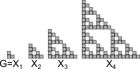
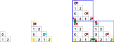
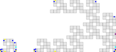
Figure 1 shows, as an example, the first stages of the discrete self-similar fractal known as the Sierpinski triangle. In this example, .
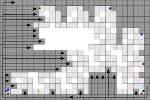
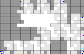
We also define a subset of connected discrete self-similar fractals which we call singly-concave as containing any connected discrete self-similar fractal such that, if stage 2 of , , is contained within a bounding box, on the straight line path from any point on the bounding box into the first location adjacent to , the set of all edges along which is adjacent to are contiguous. Intuitively, singly-concave fractals do not have concavities which occur within the “sides” of other concavities. Examples can be seen in Figure 2.

4 Strict Self-Assembly of the Discrete Sierpinski Triangle
Theorem 4.1
There exists an STAM system = (T, 1) such that has exactly one infinite terminal supertile , and , i.e. is exactly the discrete Sierpinski triangle, and for all such that .
Proof
We prove Theorem 4.1 by construction, and thus present an STAM tile assembly system and show that it strictly self assembles , while any assemblies which detach from the assembly (or otherwise form) during its growth (which we call “junk” assemblies) all become terminal at sizes . At a high level, uses 2HAM principles (i.e. combinations of large supertiles) to combine a northern, southern, and western version of each stage for through geometric matching, to produce stage . In this section we provide a functional overview of the construction, and full technical details and tile type definitions can be found in Section 5.
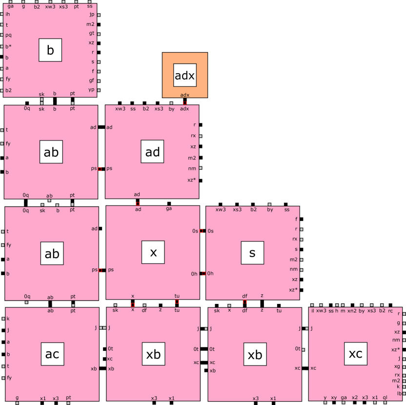
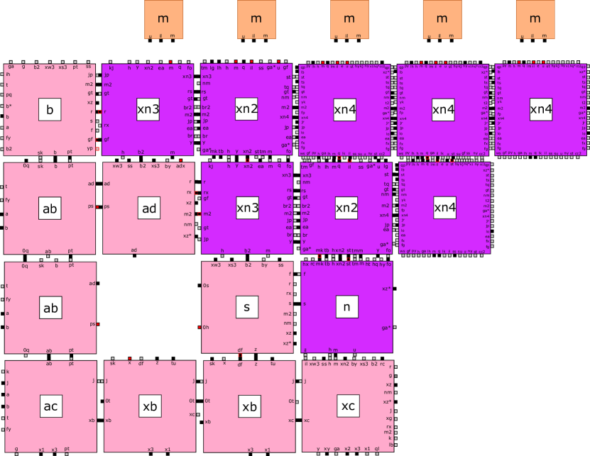
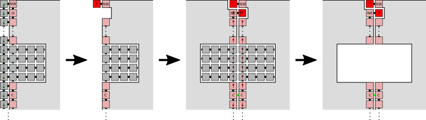
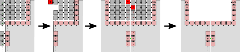
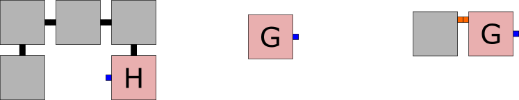
From a “hard-coded” start at stage two (i.e. base tiles initially combine to form this stage before allowing formation of subassemblies), each stage must completely grow before the subassemblies that make that stage are able to combine and form the next stage, . Only when an assembly representing stage is completely built can an initiator tile attach to it and turn on a specific glue that allows for nondeterministic binding of one of three tiles, which then tells that copy of stage to become one of three substages for stage . By definition of the Sierpinski triangle, there are three substages of each stage that correspond to the three points in the generator, i.e. , , and . The nondeterministic binding of one of the initiator types initiates an assembly sequence which grows either a tooth or gap on the assembly to which it is attached. A tooth is a one-tile protrusion from a flat surface, and a gap is a one-tile cavity in a flat surface (see Figure 3 for examples). One produces a southern tooth and becomes the northwest portion of stage n + 1, and a second produces a western tooth and becomes the southeast portion of stage n + 1; the third goes through two main phases, first filling in along the diagonal to roughly make a square with a gap in the north face and then opening a gap in the east after connecting to the northern piece to allow its connection to the eastern piece. We will call the substage assemblies , , and , respectively, and the tile sets (which are subsets of ) that form them , , and . Note that the glues that allow connections of the substages are only activated after the necessary geometry is in place to verify the sizes of the complementary pieces; after the substage connections, all tiles not within the domain of stage fall off of the assembly.
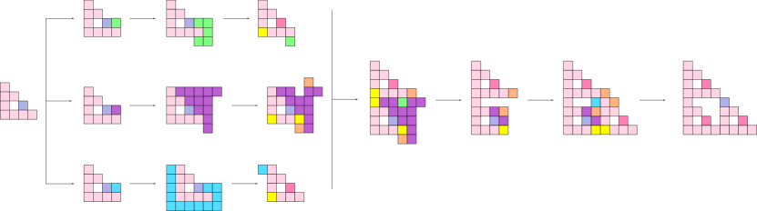
As depicted in Figure 3, and are the first subassemblies to combine with attachment points on the southwest and northwest corners of their respective assemblies. The southern tooth of , depicted in green, aligns with the slot created in the assembly, shown in purple. The two assemblies can only align when they are of the proper size due to the orange blocker tile located to the immediate right of the slot. cannot decay appropriately (i.e. cause “unwanted” tiles to fall off) until this blocker tile is in place; only after the blocker tile binds does a series of glues activate that result in the removal of the gap tile. After a sequence of detachments removes the uppermost row and eastmost column of the resulting assembly, a second blocker tile attaches to the southeastern corner of the assembly, finishing the decay and enabling the alignment of the assembly of the same stage. A final series of decay removes all other tiles that do not fit with the formation of stage of the Sierpinski triangle.
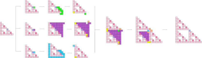
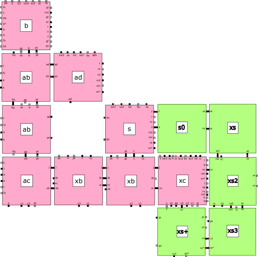
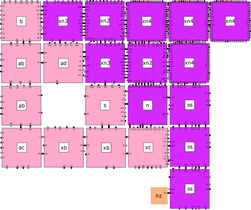
Assembly of substages and complete stages after the first combination depicted in Figure 4 follow the same general pattern of creation and decay, with few notable differences. The formation of the subassemblies does require slightly more intricate systems of signals, largely to create the stair-step mechanism seen in and .
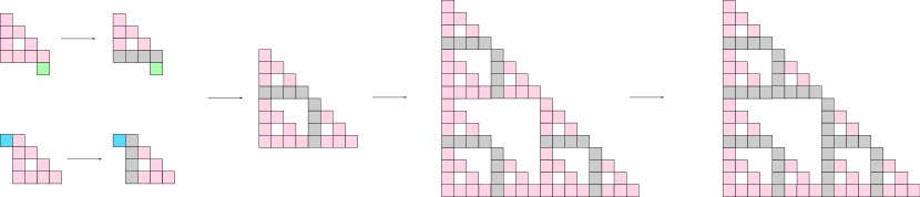
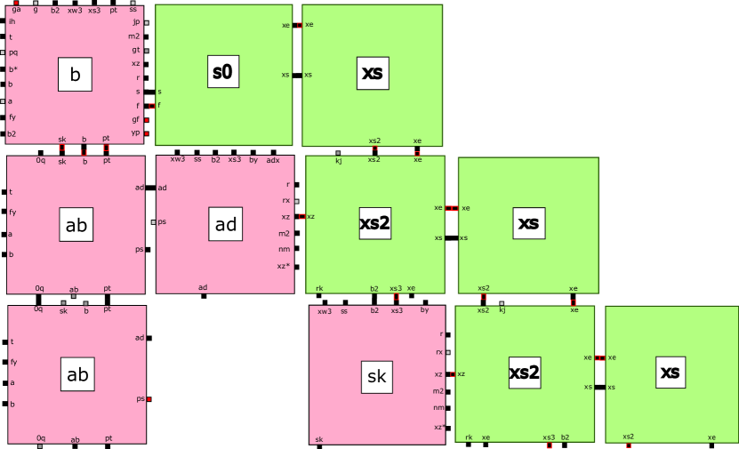
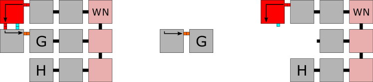
Due to STAM properties that maintain that no tile can send its signals more than once, care has been taken to ensure that no signals sent through the tiles of the tile set are used more than once. As shown in Figure 5, the two regions that send signals through the base tiles are never in a location to be used for the same horizontal or vertical signal paths more than once.

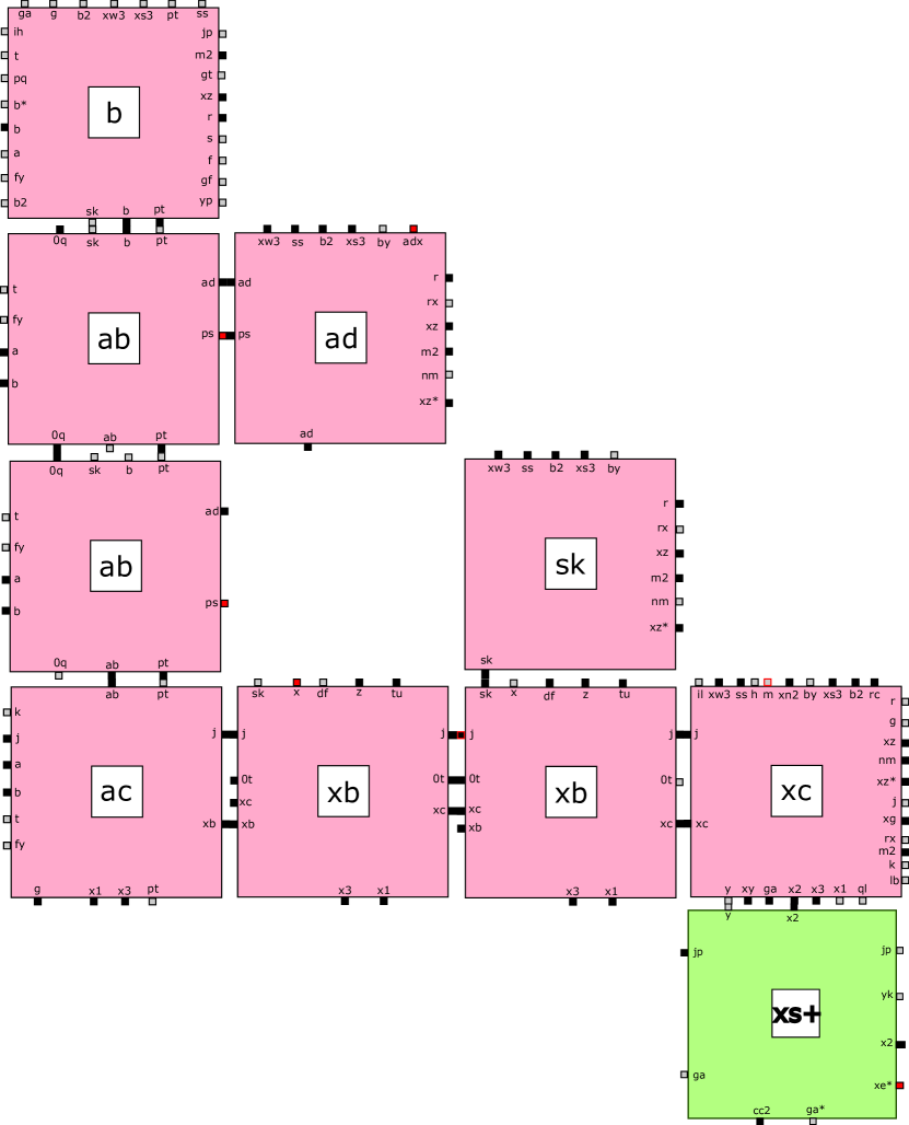
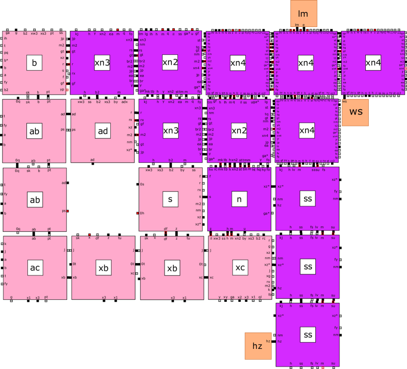
Throughout the assembly process, junk tiles and subassemblies are continuously removed with the help of blocker tiles. Figure 6 displays this process for . Each junk assembly removes itself only when the appropriate signals have been passed through it and, for many assemblies, a corresponding blocker tile has attached. This prevents active bonds that cannot be guaranteed deactivation within the asynchronous STAM model from potentially interfering with active constructions. By binding a blocker tile, junk assemblies are created with no volatile perimeter glues. Blocker tiles also change the geometry of the junk assemblies to prevent any interference.
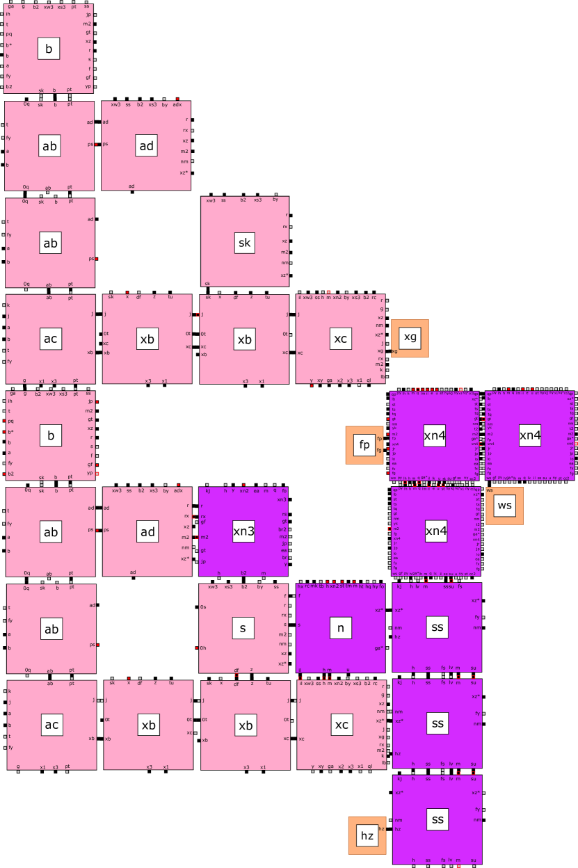
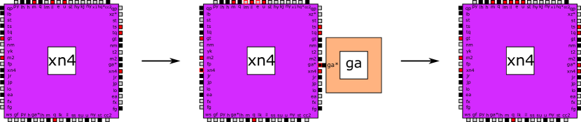
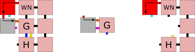
It is worth noting that some junk assemblies, particularly within the set, are capable of interacting with subassemblies at various stages. The glues that are capable of interaction on these assemblies, however, have already had their signals used and function like existing blocker and helper tiles. This means that their interaction does not result in a negative impact on the assembly as a whole, instead assisting in the proper formation of stages.
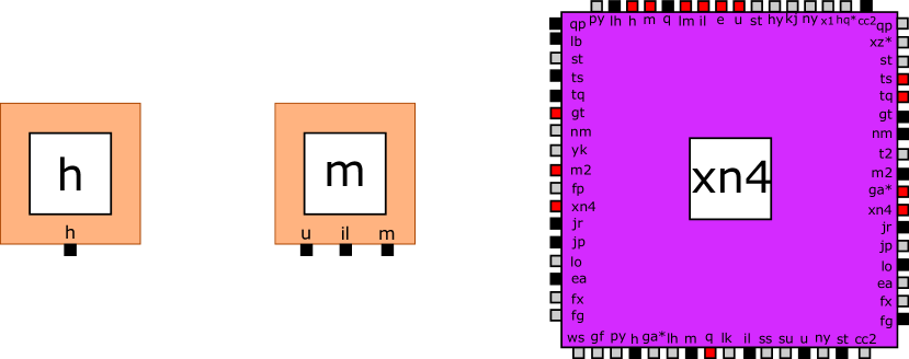
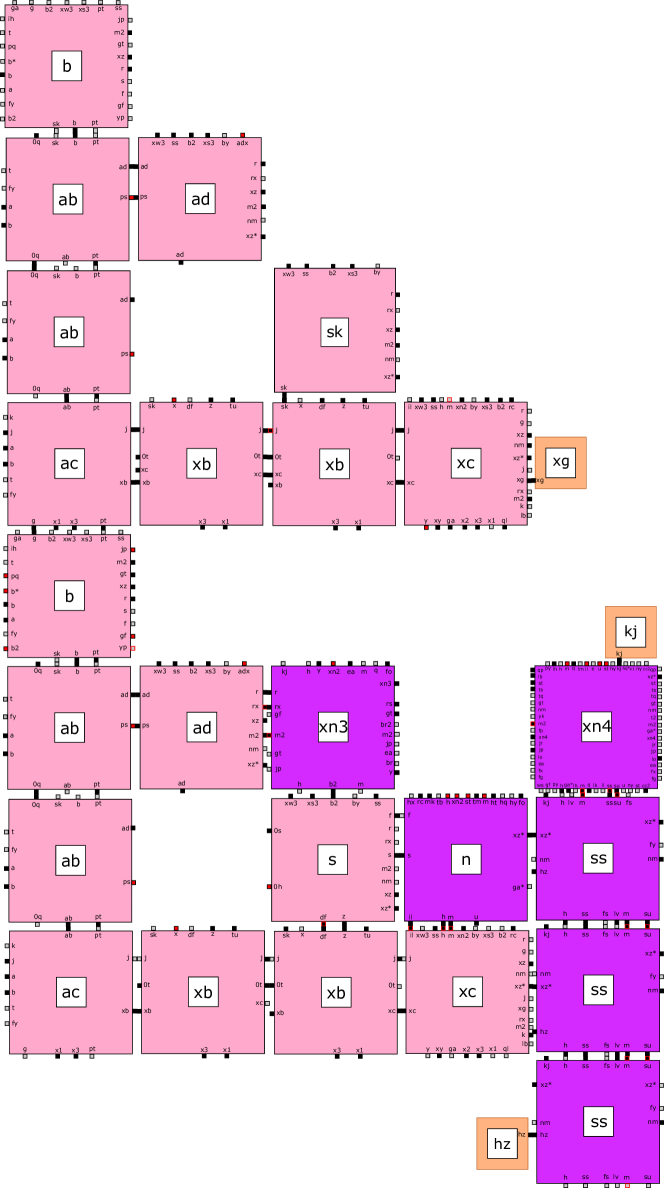
Figure 7 depicts an example of the previously described scenario. In this case, the xn4 tile functions like either the m or h tile, depending on which of its glues bind. The only glues that remain exposed in junk assemblies are either capable of performing a similar function, or do not interact with subassembly formation due to their counterpart glues turning on in isolation (i.e. a western counterpart for an eastern glue turns on only when a tile has attached to the eastern face of the tile in question).
In this process in which three separate versions of any assembly at stage n form and combine through the creation and alignment of teeth and gaps to ensure proper size integration to produce stage n + 1, and as throughout the process of assembly the junk assemblies are detaching in constant sized pieces that will not interact with the assembly in a negative manner, the correct strict self assembly of the Sierpinski triangle at scale 1 is produced.
In this section we have provided a high-level overview of the construction. The next section contains technical details and the full tile set.
5 Technical Details for the Sierpinski Triangle Construction
Here we provide the technical details for the construction of the discrete self-similar Sierpinski Triangle at temperature one. The tile sets for the assembly are provided below.


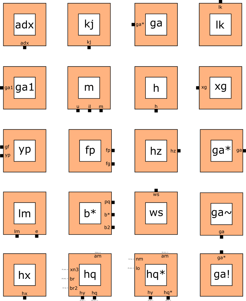
Helper tiles have been classified in this manner because they do not fit in the general geometry of the subassemblies, but they are essential in ensuring proper formation of . The smaller size shown in the figures merely identifies the particular tiles as helper tiles and is not indicative of any difference in importance or function. Many of these tiles, such as kj and xg, are blocker tiles that prevent the interaction of volatile glues, which cannot be guaranteed to turn off before detachment from a subassembly, from interfering with further fractal growth. Other tiles, such as m, serve as activators for particular glues within assemblies. These activators are external (i.e. not part of the subassembly tile set) to ensure that particular glues are only activated when exposed in a manner that cannot be guaranteed solely by tiles in subassembly tile sets.
5.1 Formation of Base
Assembly of begins with the binding of hard-coded base tiles to form the second stage of .
The base tiles, shown in Figure 8, initially bind in a particular order that prevents interference from already formed assemblies and junk assemblies. Key points in this binding pattern are described here and the overall assembly is displayed in Figure 13. To prevent rebinding of the s tile after it detaches at the end of subassembly formation or combination, the x tile cannot detach until its eastern 0h glue binds; this glue is turned off on detached s tiles, which will eventually turn of their western 0s glues. To prevent rebinding of the b tile after it detaches, the adx tile must be in place. Because detached b tiles that have already been used are bound with at minimum one eastern tile, the adx tile does not allow the junk assembly to interfere with base tile assembly. Instead, new b tiles are the only ones capable of joining. Only after attachment can the base tiles turn on their glues that interact with other portions of to form subassemblies and expand .

After the detachment of the adx and x tiles, which play roles in the formation of the stage two but do not comprise the base itself, the initial combination of base tiles of at stage two is ready to begin formation of subassemblies. At this point, depicted in Figure 14, all glues necessary to form any of the three substages are on and an initiator tile can bind with the initiator point (i.e. the glue s).
Due to the nature of the STAM, subassemblies of various sizes and types are grown simultaneously. Here, we will describe the three subassemblies , , and separately, in no relation to the order that they occur.
5.2 Formation of the Subassembly
Formation of the south tooth and the assembly consists of a series of tiles that wrap around the southeast portion of the base assembly before terminating at the southern face of the southeasternmost tile and beginning the series of detachment. At larger stages, a “stair-step” pattern is used to move around the southeastern portion of the hypotenuse of .
South tooth assembly begins with the binding of initiator tile s0 to the base assembly. This turns on an eastern glue, which enables binding of the next tile, that then presents a southern face. The tile that binds to this southern face senses whether it is next to a hypotenuse tile or the southeastern corner tile; at the stage depicted in Figure 15,it is next to the corner tile and therefore activates a southern glue. If the xs2 tile was not next to the corner tile, as shown in Figure 16, a series of alternating xs2 and xs tiles forms the stair-step pattern. Once the tiles reach the southeastern corner, the xs3 is added to open a western face and allow attachment of the xs+ tile. This tile can only bind to the western glue activated on the xs3 tile and can therefore only attach under the southeastern corner tile. Once the xs+ tile has bound, detachment can begin.
Stair-steps form to maneuver around the hypotenuse of the base assembly. General assembly of the stair-steps begin with the addition of a tile to the southern face of the tile to the right of the initiator tile (such as xs2 below the xs tile in Figure 16). If this added tile senses that it is next to a corner of the hypotenuse, it opens an eastern glue that allows the binding of another tile that then opens a southern glue. The process then begins again, continuing until the stair-steps reach the southeastern xc corner tile. At this point, different glues on the eastern face of the base tile turn on a southern glue for the xs2 or similar tile, preventing further eastern expansion and causing the growing assembly to turn the corner and continue growing.

Detachment of the tiles begins with an exit signal that is sent through all attached tiles, back to the initiator tile and through to the base tile that presented the initiator glue. Removal of this base tile is necessary to prevent interference with other assemblies — otherwise the on initiator glue and the initiator tile would both have to simultaneously deactivate the same glue, something that cannot be guaranteed in the STAM due to its asynchronous nature (i.e. both tiles containing those glues could receive signals to deactivate them, but one may turn off before the other, allowing detachment while the other is still temporarily on). Therefore, the base tile, initiator tile, and the tile to the immediate right of the initiator tile are removed in a size 3 junk assembly. The xs3 tile detaches with an active north face glue that could bind to other active subassemblies, but helper tiles prevent permanent attachment, as explained later. The xs2 tile, and therefore the strings of 2 tiles that form the stair-steps, cannot detach until a blocker tile binds to its northern face. This prevents interference from the northern xs2 glue that cannot be guaranteed to turn off and could otherwise interact with other subassemblies. In this manner, all tiles that do not comprise the south tooth itself are removed in junk assemblies.
The addition of the sk tile replaces the removed base tile, explained in the previous paragraph, and reforms the base. It acts like the already present ad tile. The subassembly is ready for combination with the subassembly after this addition and after the binding glue on the southwestern corner tile has been turned on. This glue is activated after the xs+ tile binds with the southeastern corner; a series of signals is sent through the base tiles to turn on the glue. Signals can be sent through the base tiles because the south row of the subassembly becomes the middle row of the next stage and will never need to be used in the same manner again, as depicted in Figure 5. Now, is ready to begin combining with other subassemblies to form the next stage of .

5.3 Formation of the Subassembly
Formation of the west tooth and the subassembly consists of a series of tiles that wrap around the southeast portion, the southern face, and western face of the base assembly before terminating at the western face of the northwesternmost tile and beginning the series of detachment (as shown in Figure 19. At larger stages, a “stair-step” pattern is used to move around the southeastern portion of the hypotenuse of , similar to the south tooth assembly, as seen in Figure 16. After the stair-step, two tiles attach to the south, presenting a west face. A tile then attaches to the west, turns on a northern glue, and if the tile detects it is below the assembly, it subsequently turns on the appropriate glue on its west face. Once the tile is unable to detect the assembly above it and has an exposed north face, a tile can attach to the north. The tile turns on an eastern glue to detect its relation to the west edge of the assembly, and opens a north face glue until it reaches the top b tile. The tile that attaches to the top b tile becomes the west tooth and causes the stage to begin detachment.

Detachment of begins with an exit signal sent through all attached , starting from the top b tile (the tile that stays in place and becomes the west tooth). The stair-step detaches similarly to the way the stair-step detaches in the south tooth assembly, as seen in Figure 16. After the stair-step detaches, the bottom rightmost tile detaches, allowing a helper tile to attach in its place. The helper tile sends a signal through the bottom row of tiles, allowing another helper tile to attach to the left, and causing the bottom row to detach. A helper tile is then able to attach to the south of the leftmost column of tiles, causing a exit signal to pass through the leftmost column and the remaining four tiles to detach. Throughout the detachment similar precautions were taken to the precautions taken in the south tooth assembly to ensure nothing can attach to the completed stage, except via the west tooth. For example, tiles attached to the bottom or west faces of the base cannot detach until a blocker tile is in place to prevent interaction of volatile glues.
5.4 Formation of the Subassembly
Formation of the upper gap and the subassembly consists of a series of tiles that fill the space above the hypotenuse of the stage before sending a series of signals, with the help of a blocker tile, that results in the removal of a single tile to form the upper gap. Larger stages follow the same general principle of assembly, with the only difference being the sequence of tiles a particular detachment signal is sent through.

Upper gap assembly begins with the binding of initiator tile n to the base assembly. The n tile subsequently turns on a northern glue, beginning the stair-step proliferation of tile types xn2 and xn3 along the hypotenuse of the assembly. After the western xn3 tile binds to a row in the stair-step, the xn2 of that row turns on an eastern glue that enables further filling of space. This eastern glue can turn on before the completion of the stair-step because the filler tiles that will bind to it can only extend to a certain length, as described below, which prevents unchecked growth.
As depicted in Figure 22, addition of xn4 tiles fills a large portion of the space above the assembly. Each xn4 tile can only turn on its respective eastern glue, allowing for another xn4 tile to bind, when it has bound to a tile underneath it. However, because the n tile that binds immediately above the initiator tile site has no xn2 or xn4 tile underneath it, it can not extend an eastern glue. This prevents unchecked growth of the xn4 tiles to the right and results in an inverted stair-step appearance. This inverse stair-step carries a signal that turns on southern glues only on the tiles that have a southern exposed face and are part of the immediate inverse stair-step. Additional filler tiles can then attach to these tiles and fill in the remaining area above the hypotenuse of the subassembly.
The addition of the ss tiles takes place in a similar manner to the addition of the xn4 tiles — only when the ss tile is next to a western tile that presents a particular glue can it turn on a southern glue, allowing for further assembly. Due to this, the ss tile column directly to the side of the southeasternmost corner tile extends one below the south face of . A blocker tile binds to this extending ss tile to prevent interference after it detaches. The binding of a ss tile to the southeasternmost corner tile xc also turns on the connecting glue on the eastern face of said tile. This connecting glue is not exposed until detachment of the ss tiles, which does not occur until after the and subassemblies combine.
A series of signals that stems from the northern face of the southeastern xc corner tile travels north, eventually signaling the tile that will be removed from the filler tiles to form the upper gap as well as the tile to which a blocker tile will bind. This presents the only major difference between the first stage of assembly after formation of the stage two and the other stages — this northern signal must move through a series of ss tiles at larger stages. This, however, does not present any changes in the overall construction. After these signals have been sent, a blocker tile attaches to the xn4 tile that lies to the immediate right of where the gap will be. Only after this blocker tile has attached can a series of western-moving glues be initiated, the gap tile be removed, and the connecting glue on the northwestern b corner tile be turned on.

The subassembly shown in Figure 25 is ready for combination with the subassembly at this point.
5.5 Combination of Subassemblies
The first portion of subassembly combination involves the binding of the and subassemblies. The southern tooth of the subassembly fits into the slot formed by the upper gap; the blocker tile to the right of the upper gap ensures that only the appropriate-sized subassemblies combine. Appropriate sizing of subassemblies is also guaranteed by only one connecting glue on the and subassemblies that can bind to one another; this glue is located on the northwestern b tile of the subassembly and the southwestern ac tile of the subassembly. The combination of these two subassemblies results in the detachment of the northern row of filler tiles, the south tooth, and the rightmost column of ss filler tiles.

Upon binding the connecting glues of the and subassemblies, as shown in Figure 26, the connecting glues activate a variety of signals in the base tiles. The southwest ac tile of activates a southern glue that is used if the resulting stage of differentiates into a subassembly. The northwest b tile of turns on two western glues — one that serves in the possible formation of a subassembly and another that binds a helper tile. This helper tile deactivates western glues on the b tile that would result in premature termination of the assembly (if this stage of differentiates to a subassembly). Only after this helper tile b* has bound does a series of eastern glues travel through the northern row of the filler tiles, initiating detachment. The first tiles to be removed are the xn3 and xn2 tiles, which detach as a pair. At larger stages, the row of xn4 tiles that precede the south tooth are removed through the help of a blocker tile that ensures all volatile on glues cannot interfere with other assemblies.

Only after the addition of the blocker tile xg to the southeast xc corner tile of what was the subassembly can the south tooth begin to detach. Through interactions with southern glues on the xc tile (after it binds to xg), the south tooth turns on a western glue to which a helper tile attaches. This helper tile results in the detachment of the xs+ south tooth. The filler tile to the immediate south of the xs+ south tooth is also removed as a result of these signals. This removal is necessary to prevent interference of junk xn2 tiles with the subassembly and with other xn2 tiles.
The end portion of the top filler tile row can only be removed after the binding of a helper tile fp, which sends a series of signals resulting in the turning off of glues holding the set of tiles in place. This removal creates a space for a helper tile to interact with the rightmost column of filler tiles. The assembly depicted in Figure 28 and Figure 29 depicts a column composed only of ss tiles. However, larger assemblies also feature xn4 tiles in this rightmost column — detachment of the xn4 tiles follows the same pattern of detachment seen in ss tiles (e.g. involving a helper tile).
The filler tiles in the eastern row are removed through the assistance of a helper tile; only after the helper tile kj has bound can western glues be turned off and the filler tiles removed. After removal of the column of filler tiles, the binding glue on the southeastern xc corner tile is exposed, allowing binding of the subassembly. This can happen before the binding of the helper tile, as depicted in Figure 30, because after binding of the subassembly occurs, nothing else can take place until the helper tile hq or hq* (depending on if a n or xn4 is presented for binding) attaches. Addition of the helper tile results in an interface that allows interaction with the west tooth x2+ tile.
The second portion of subassembly combination involves the binding of the subassembly and the subassembly formed in the first portion of combination. The western tooth of the subassembly fits into the slot formed by the combination of and . Proper sized assemblies are ensured to bind together in the same manner as the first portion of subassembly combination (i.e. blocker tiles and only one connecting glue being on). This portion of combination results in the removal of all filler and helper tiles and leaves the newly-formed stage of ready for differentiation.
After the connecting glues of the subassembly and what was the subassembly bind, the connecting glues activate a variety of signals in the base tiles. The southeast xc tile of the former activates a variety of glues that are used if the resulting stage of differentiates into a or subassembly. The southwest ac tile of turns on a northern glue that carries a signal through the base tiles of the subassembly (which can happen because these tiles are never used for the same purpose again, as shown in Figure 5). This signal turns on an eastern glue on the b tile, which binds with a helper tile. The binding of this helper tile yp ensures that glues on the northwestern b that could potentially interfere with assembly are turned off. Only after the binding of this helper tile can western signals be initiated; these signals result in the detachment of the west tooth, as well as interaction with the helper tile and filler tiles.

The final portion of the stair-step, which includes the helper tile hp as shown in Figure 31, detaches in the same manner as the other portions of the stair-step pattern. However, the helper tile that results in this detachment does not turn on until hp has interacted with the west tooth tile. This interaction results in the removal of the x2+ west tooth tile as well. At larger stages, additional filler tiles must be removed; these decay in a manner almost identical to the previous detachment of similar tiles.

The addition of a helper tile to n results in the removal of the initiator junk assembly for the subassembly. Removal of the base tile that presents the initiator glue for occurs for the same reason as in and , and an sk tile will fill in the resulting gap (as shown in Figure 34). Activation of the northwestern b tile in the former subassembly occurs after the binding of a helper tile. This can happen before the removal of all filler tiles from the interior of the combination of the three subassemblies, and this is able to happen because this interior area will never interfere with differentiation and future growth.
After the addition of the sk tile and activation of the new base tile initiator point, the resulting stage is complete.
5.6 Examples of Junk Assemblies
All junk assemblies that detach during formation of reach a terminal size of and do not negatively interfere with the assembly of other stages. Although there are a variety of different junk assemblies, we will discuss the major groups of junk assemblies and the steps taken to ensure that these assemblies cannot interfere with assembly.
One variety of junk assembly is a single tile that detaches from the overall subassembly with a glue still on that could interfere with other assemblies. The xn4 tile removed to form the upper gap is depicted in Figure 35 and falls into this category. Upon detachment, this xn4 tile has a western xn4 glue that could interfere with formation of . To prevent this problem, a helper tile can attach to the single junk tile and turn off this interfering glue. Although the tile can attach to other assemblies before this glue has been turned off, any other glues that could interact with active assemblies are turned off, resulting in the interfering xn4 tile eventually being removed with no damage.
To prevent interference between the initiator tile and the initiator point on the base assembly, the two tiles are removed as a single junk assembly with the volatile interface hidden from solution. This is depicted with the initiator junk assembly in Figure 36. The gap in the overall assembly formed by this removal is filled by a sk tile. All northern glues that are potentially on after detachment of the initiator junk assembly are eventually turned off and do not negatively interfere with the growing assembly.
Although the initiator tile and initiator point on the base assembly for the subassembly are removed in a pair for the same reason as the other two subassemblies, it undergoes a slightly different process due to the subassembly’s formation. Because grows an upwards stair-step instead of one moving down, like in , the junk assembly displayed in Figure 37 requires a blocker tile before removal to prevent interference by the n tile. Other than these two differences, the initiator junk assembly for follows the same pattern as the other two initiator junk assemblies.

Due to potentially problematic glues that cannot otherwise be guaranteed to turn off or not interfere with assembly, many tiles are removed in groups of two or three with the addition of a blocker tile. This is depicted in Figure 38 for a set of tiles from the subassembly. Because these junk assemblies cannot detach from the overall assembly until a blocker tile is in place, all volatile glues are prevented from interfering with parallel and future assemblies.
The same principle is used for single tiles as well, as shown in Figure 39. In these scenarios, individual junk tiles cannot detach until a blocker tile covers a potentially problematic glue. Any other glues that could bind to separate assemblies are ensured to not cause problematic growth and are eventually turned off by a helper tile that binds to the junk tile.

In this way, the discrete Sierpinski triangle is assembled at temperature 1 and all produced junk assemblies are of size .
6 Self-Assembly of Arbitrary Discrete Self-Similar Fractals
In this section, we state and prove our main theorems, which are generalizations of the techniques of Theorem 4.1, related to the strict self-assembly of arbitrary connected discrete self-similar fractals using temperature 2 STAM systems, and an infinite set of such fractals using temperature 1 STAM systems.
Theorem 6.1
For any connected discrete self-similar fractal , there exists an STAM system such that has exactly one infinite terminal supertile , and , i.e. is exactly the discrete self-similar fractal , and for all such that .
Theorem 6.2
For any connected discrete self-similar fractal which is singly-concave, there exists an STAM system such that has exactly one infinite terminal supertile , and , i.e. is exactly the discrete self-similar fractal , and for all such that .


Proof
The proofs of both Theorem 6.1 and Theorem 6.2 are nearly identical, with only a very small difference, so we present a single proof and will mention that single point of divergence within it. Our proof is by construction of the necessary STAM systems given fractal definitions as input. The following provides an overview of our construction, and we note that a very large portion of the basic tiles and gadgets needed to carry out this construction are based on those used in the construction for the Sierpinski triangle, often requiring differences in just scaling, rotation, or number of signals. Therefore, we present most of the tiles and signals at a high enough level to convey the design and rely on subsets of the specific designs of tiles and signals from the previous construction, only presenting specific tiles and signals in locations which are significantly unique.
Let be a discrete self-similar fractal, and let be the generator for . We now present a description of how to algorithmically generate a tile set such that the 2HAM system creates a unique infinite terminal supertile of shape , along with all other terminal assemblies being “junk” assemblies whose sizes are all .
Our construction will start growth of at stage 2, i.e. , with tiles from directly combining to form in such a way that every point of receives a unique tile type, which is done by creating a tile type for each position with a glue unique to each pair of adjacent sides between two such tiles. This means there are unique glues to each pair of interior edges, and to create the glues for the exterior edges we will perform an analysis of the generator as follows. At this point we also mention that, since we are discussing the constructions of both Theorem 6.2 and Theorem 6.1 in parallel, all signals, tiles, and glues throughout both constructions are identical except for the fact that in each, all glues are -strength, where for the construction of Theorem 6.1 and for the construction of Theorem 6.2, for every case except for a very few glues which will be specifically mentioned later.
First, we will locate a perimeter location on to serve as the initiator location where tiles can attach to begin growth of stage 3. Let be the rightmost point in the second row (from the bottom) of the rightmost copy of in the bottom row of copies of in . (See Figure 40 for a few examples marked as aqua tiles in each stage 2.) The tile which attaches in position has an east facing glue of type init (which will allow for the attachment of an “initiator” tile). Additionally, let be the rightmost point in the second row of the rightmost copy of in the second row (from the bottom) of copies of in . The tile which attaches in position has an east facing glue of type preinit. Intuitively, the tile at this position will have the ability to transition into a state with an init glue active if it happens to eventually be located in the unique position of a fully completed stage allowing it to begin the transformation of that assembly into one of the substages of the next stage. (Note that the initiator location must be in a location which is maximal for the side it is on, in this case the east side. Therefore, if the location that was selected above does not happen to be on an easternmost tile, we will instead put it on either location or , one of which must be in the generator of a connected discrete self-similar fractal and thus also . Then, all directions of the following construction can be either rotated 90 or 180 degrees clockwise, respectively, and references to the location of the initiator point can be updated to the new location. This results in conceptually the same construction so, without loss of generality, we will continue or description assuming the originally stated location and assuming it is on an easternmost location of .)
We mark the extreme points of each side with special exterior glues. In the westernmost column of tiles which form , the topmost has a northern glue of type end which is specific to that corner, and similarly so does the southern glue of the bottommost tile. Analogously, such “end marker” glues are located on all 4 sides. See Figure 41 for an example (specifically, the blue glues). We also place special preconnect glues at the four locations which could possibly be used to connect one copy of a stage to another, depending on which substage locations they represent within the next larger stage. These are located on the north and south sides of the leftmost location which both the top and bottom row, respectively, have in common. There is guaranteed to be at least one such location since the fractal is connected, and therefore at least one position aligns between two copies which are placed with one directly above the other. Similarly, the horizontal connection points are marked. See Figure 41 for an example (specifically, the yellow glues). Note that on there will actually be a set of different types of preconnect glues in each such position, and the determination of those types will be discussed later. The final glues that we add to the perimeter of the tiles of are glues which are specific to the direction that each of the external edges of any of those tiles face, i.e. there are directional glues labeled ,,, and and ,,, and which are on each of the corresponding sides of tiles which are on the exterior of . Those glues are on on any tile sides which do not have any of the previously mentioned special glues such as preinit, preconnect, etc., active. For sides with one of those special glues on, the directional glues begin in the latent state, and when the special glues are all turned off on such a side, the directional glues of that side is then switched on. Additionally, these are some of the few glues which differ between the constructions of Theorem 6.2 and Theorem 6.1, and instead of being -strength for each, the directional glues are strength-1 in both constructions.
We now define a spanning tree through the graph of such that the root is at the rightmost location of the bottom row of (i.e. for
) and which is constructed as follows. Beginning from point and assuming an orientation facing to the west, add the second node by adding either the node to its west if it exists in the generator, and if not, turn right (facing north) and add that point. Continue by following a depth-first-search to build a spanning tree which always attempts to take the leftmost available option when there are more than one adjacent points which have not already been added to the tree. See Figure 42 for examples.

Using the spanning tree , we will now define an ordering by which the substages of stage , for , combine to form that stage. Simply, we start from the furthest leaf from the root in (and if there are multiple leafs at the same distance, randomly select one). The substage representing that node will first connect to one representing the location which comes immediately before it on the path backward to the root. Subassemblies representing each leaf location will combine to those preceding them on their branches, with each branch assembling in parallel. Whenever there is a “base” node from which more than one branch goes outward, an ordering by which the branch assemblies attach to the assembly representing that base node is set as follows. From the side of that node which attaches to the node along the path back to the root, i.e. the one which is closer to the root in , traverse the sides in counterclockwise (CCW) order and set the ordering of attachment to be the order in which the branches are encountered, with side being the final side in the ordering. After this attachment, growth continues toward the root in the same way until reaching the root. Examples of orderings can be seen in Figure 42 by following the paths in reverse.
Beginning from the initial formation of stage 2, our construction will guarantee that only once a stage is complete, i.e. the assembly representing it has a tile in every position which is defined for that stage of the fractal (assuming the assembly is translated to ), can the necessary glues activate and structures form which allow it to combine to other assemblies representing exactly the same stage. For stage 2 assemblies, this is enforced by a “circuit” of signals which are encoded in the tiles so that as tiles bind to form a stage 2 assembly, a “completion” signal propagates so that if and only if every tile of stage 2 has attached does that signal arrive at the single tile which has the init glue on its east side. At that point, that glue is turned from latent to on. This guarantees that only completed stage 2 assemblies can begin the process of combining with other assemblies, and starting from that base case we will prove inductively by our construction that all subsequent stages must correctly complete before allowing additional combinations.
Therefore, assume that only assemblies representing complete stages of have init glues which are on, and that each such assembly has exactly one init glue active on its perimeter. (Note that it may be the case that there are some extra tiles bound to such an assembly for stages , but any such tiles not included in the domain of the matching stage of will be guaranteed to fall off eventually. Although the exact timing of their detachments cannot be guaranteed due to the asynchronous nature of the STAM, no such lingering tiles can cause incorrect growth or attachments, but can only temporarily delay correct forward growth of the ultimately infinite structure.)
Let be a producible supertile in which represents stage of and which has a single init glue active on its perimeter. In , there are a subset of tile types called initiators, and there are exactly of them, i.e. one for every point in the generator of . Nondeterministically, a tile of any initiator type can bind to . Assuming that the initiator which corresponds to binds to the init glue of , and that in the tree the node at location is connected to nodes in the set , that will begin the following series of tile attachments and detachments which ultimately result in binding to supertiles representing each of the points in . We call this the process of differentiation since an identical set of supertiles nondeterministically (by the type of initiator which attaches) each transform into supertiles able to represent different substages of the next stage.
6.0.1 Substage differentiation
For each initiator tile type, there is a unique set of tile types which bind to it to grow paths and portions of assemblies necessary for the particular process of differentiation needed for the generator point that the supertile will eventually represent. The actions needed for differentiation to any particular type are completely determined by the shape of the generator, and independent of the stage of being formed.
As previously mentioned, as soon as a supertile completes growth into a stage of , it has exactly one init glue active on its perimeter. Another invariant which is maintained for all such stage-complete supertiles is that they also have exactly the following numbers of each of the following types of glues active on their perimeters: one preinit glue (which is on the east side), one preconnect glue on each side, and one end glue on each of the two extreme points in each direction (e.g. the north sides of the northernmost of the westernmost tiles and the northernmost of the easternmost tiles are marked as the extreme left and right points, respectively, for the north side). Since every such location in a stage 2 supertile has the corresponding glue on, as those supertiles combine to form larger stages, in order for the proper number of each type of glue to be active, appropriate subsets of those glues must be deactivated (and sometimes others, such as connect activated). We now discuss how it is determined which such glues of each differentiating substage need to be activated or deactivated.
-
1.
end glues: A key observation to the management of the end marker glues is that, for instance, the tile with the left end marker of the north side of stage is the northernmost of the westernmost tiles of stage , which is exactly the northernmost of the westernmost of the tiles that make up the substage supertile which attaches in the northernmost of the westernmost positions of . Thus, for every end marker glue, there is exactly one substage which its supertile can differentiate into for the next stage in which that glue should remain on. Therefore, during differentiation, every end marker glue is forced to turn off except for those which will also mark the extreme points of the next stage.
-
2.
preconnect glues: There is a preconnect glue active on the side of each direction. By noting which sides of the location in are attached to neighboring points, we can determine which subset of directions will require that their preconnect glues are deactivated and replaced with connect glues (so they can bind to the necessary substage supertiles, to be described below). Furthermore, as previously mentioned, there are actually a set of preconnect glues in each such location, with one being specific to each pair of substage locations which could bind along that boundary. In the following, we assume that the correct preconnect glue of that set is selected to turn on a similarly specific connect glue and discuss the paths of tiles which do this later. Now, in a manner analogous to the way the end glues correspond to positions in the supertile of the next stage, we note that only a supertile which forms a substage corresponding to a generator position which has the northern connect glue can be in a position in the next stage to possibly contain the northern connect glue which may be needed to bind the supertile of that stage to another. Thus, we can determine if any of the preconnect glues which were not replaced with connect glues need to remain as preconnect glues for the next stage, in which they may be or may not be replaced or deactivated, depending on which substage differentiation occurs. Finally, for the remaining directions for which the preconnect glues were neither deactivated and replaced with connect glues, nor was it determined that they must remain as active preconnect glues, the preconnect glues of those sides are turned off.
-
3.
init glue: This glue is directly bound to by the initiator tile, and is turned off after attaching to the initiator tile and then receiving a signal from that tile (which it sends after verifying that the first tile along the path which grows from it has connected to the substage supertile).
-
4.
preinit glue: The final substage of stage which will bind to complete the formation of stage will be that corresponding to the location of the root of the tree , which will contain the single preinit glue of the forming stage which needs to be replaced with a init glues. For each other substage, its preinit glue will be turned off.
Given the fixed set of glues which need to be activated and deactivated for each differentiating substage, along with the locations and orderings of the sides with which the substage will need to bind to other substages, a unique set of tiles for each substage type (i.e. corresponding generator location) is created and added to which can specifically attach to that type’s initiator tile and form the paths and growths necessary for the differentiation process.
Since the ordering in which sides of a substage will need to attach to others is fixed and occurs in CCW order, a path of tile grows from the location of the init glue around the perimeter in a CCW direction until reaching the side which first needs to allow a connection. The specific way in which such a path is able to grow around the perimeter of a substage is explained in more detail in Section 6.2.1, but the general scheme is depicted in Figure 43a. It is worth noting that the final difference between the constructions of Theorem 6.1 and Theorem 6.2 occur in the tiles which form the paths which fill in the perimeters. Specifically, the glues on the perimeter paths and rows of tiles which grow from them into concavities of the substages have ,,, and glues which are able to attach to those on the sides of the substage to “detect” those sides, and these are all strength-1 in both constructions (to match those on the substages). Only once they attach to matching glues on the substage tiles do they activate the corresponding ,,, or glues which then bind to strengthen the connection (to be required later). This single difference in the two constructions, in the strength of initial binding of these filler row tiles to the sides of the substages, is necessary to prevent a problem where at temperature 1 those filler rows could allow binding between supertiles representing substages of different stages if those substages have appropriately shaped concavities. (An example can be seen in Section 6.2.1 for more details.)
Each initiator tile initially has only a single glue in the on state which binds to the init glue. After this binding, it activates a glue which allows the first tile of a new path to bind, and each subsequent tile in the path attaches in a similar fashion. While growing to the first side which needs to be configured to allow a connection, if and when the path passes the last such side in the ordering, for all sides in between the last and the first, it sends the necessary signals to deactivate and/or activate any of the marker glues (e.g. end glues) necessary for that side, as determined following the procedure mentioned above. More details about the process of activating and deactivating the marker glues can be found in Section 6.2.1. Whenever growth of a side has completed and the tiles which form the corner for the new side have attached, signals begin the detachment of the filler tiles and then the perimeter path of the completed side in the manner described in Section 6.2.1.
Upon reaching the first side which is to be configured for a connection, the following process occurs:
-
1.
The perimeter path and filler tiles grow to completely cover the side and reach the far end marker.
-
2.
Then, a signal is passed back through the outermost row which causes every location other than that which will become the tooth to detach and also for the adjacent location which will be the gap for the complementary supertile’s tooth, to detach. By default, on a western side of a supertile, the tooth is in the very top location and the coordinate of the gap is offset by from that, and an eastern side has its tooth in the second to topmost location and its gap offset from that by . (See Figure 44 for a high-level example.) For north sides, by default the tooth is in the easternmost location with the gap offset by and for south sides the tooth is in the position left of the easternmost with the gap offset by . A special case can occur when one side of a generator has only one point filled in. For example, see the west side of the generator in Figure 41 where only the southernmost location exists. In such a side, it must be the case that the tooth and gap geometry occurs opposite that location so that location can contain the connect glue used for the attachment. Therefore, if the generator in Figure 41 happened to have its only western point at the top, then the teeth and gaps of supertiles binding along east and west edges would be moved to the southern sides of those edges.
-
3.
The signal passing through the outermost row will pass the tile adjacent to the tile with the preconnect glue. There, a signal is sent to that tile to activate its connect glue. (See Figure 44 for an example.)
-
4.
The activation of the connect glue indicates that the side is configured for its connection. Once the outer row of tiles and the tile in the location of the gap have detached, the connect glue is exposed and the side is able to connect to the complementary substage supertile. Note that the connect glue which is actually turned on is selected by the specific type of path tile which activates it (which was ultimately determined by the type of initiator tile which began the path) which correctly selects from the set of preconnect glues which are specific to each pair of adjacent sides which could be connecting. Given the requirement that the tooth of a side is in place before its connect glue can be activated and that the rest of the side must already be completely filled in other than the single gap location, no supertile can combine to a supertile representing a substage different stage, an incorrect substage of the same stage, or a misaligned supertile. (Please see Section 6.3 for more details.)
A complementary supertile binds to this side via the connect glue, and this glue causes a signal to begin which initiates the detachment of the filler tiles used on that side. A signal also propagates to the next side in the CCW direction to continue the differentiation process for each side. Details of this process can be seen in Section 6.2.1. Whether or not a side is configured for, and then participates in, a connection with another substage supertile, the perimeter path and filler tiles are signaled to detach when necessary, and the ordering of those detachments as well as the specific glues which are deactivated are mitigated by “helper” tiles similar to the way there were in the construction of the Sierpinski triangle. These helper tiles generally bind on one side of a tile which must detach in order to cover active glues which could otherwise allow the dissociated and freely floating tile to later incorrectly bind to another assembly. The active glues of the other side can then be guaranteed to be deactivated because only then can the tile dissociate, resulting in sterile size-2 junk assemblies. (See Section 6.2.1 for additional details of this process.)
We now note that the signals which are used to configure the consecutive sides of the substage supertiles either (1) pass through tiles which will later detach and become junk assemblies, or (2) pass through tiles which will remain within the fractal-shaped assembly but which are contained along a side which has just bound to another substage. Since such tiles are now buried within the interior of the newly formed supertile, they will never again be required to pass signals and therefore there is no need for signal reuse (which is not allowed within the STAM).
Finally, we note that by design, the last substage supertile to differentiate will be the one representing the root position of and thus which has the preinit glue which will need to be replaced with a init to allow differentiation for the next stage. Additionally, the ordering of side differentiation for that substage ensures that that side is the final to be reconfigured, meaning that only after all necessary connections have been made will the init glue be activated. (And since this supertile represents the root node, any which attached to it could only have attached after completing all of their other attachments.) This ensures that all necessary growth has occurred for the newly completed stage, although there may still be perimeter path and filler tiles which need to finish their deactivations and detach. (Again, this is due solely to the asynchronous nature of the STAM which makes it impossible to know exactly when a tile which has received a signal to deactivate a glue will actually turn that glue off.) Nonetheless, such lingering tiles can cannot cause any incorrect binding behaviors, but can only temporarily delay the correct growth of the next stage.
At this point, the assembly of a new stage is complete, with the guarantee of all necessary, correctly formed and sized substage supertiles being attached, with the exactly correct number and placement of marker glues being active on its perimeter. It then nondeterministically binds with one of the initiator tiles to begin the differentiation process for the next stage. By the guarantees of the complete and correct construction of a supertile representing stage assuming the complete and correct assembly of the supertiles representing stage , the correctness of the construction in generating the infinite number of stages in the shape is proven.
6.1 Errors at with general fractal shapes
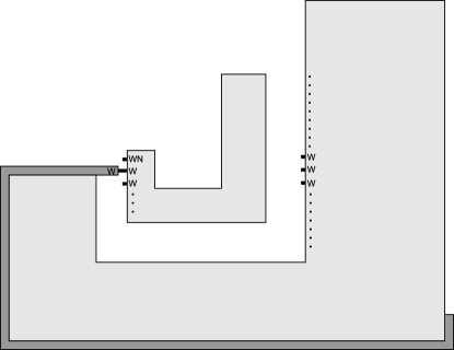
Figure 45 shows why there must be a difference between the temperature-2 construction which works with general discrete self-similar fractal shapes, and the construction which only works for a constrained subset of fractal shapes. Specifically, if a row of filler tiles can grow to a position where there is nothing below it, but its tiles also have active glues which are able to detect their eventual collision with the far wall, then at a supertile representing a smaller substage assembly could possibly bind to that row, thus incorrectly connecting supertiles of different stages. This problem is avoided in the construction by making these glues strength-1, thus preventing them from having enough strength to bind the supertiles, along with the fact that only one such row can be growing at a time and thus exposing such glues, and the pattern of the eventual decay of those filler rows is also carefully designed to prevent the ability for erroneous binding.
6.2 Technical details for the general fractal construction
6.2.1 Perimeter paths and filler tiles
In the general construction, to prepare a supertile representing a stage of the fractal for binding with another such supertile, we must first grow paths of tiles around the supertile in such a way that filler tiles are placed to make the side of a supertile a contiguous set of tile locations that actually contain tiles. The construction of this path is depicted at a high level in Figure 43a, where tiles grow a path along the south and west edges of a supertile. Tiles to grow a path along the north and east sides of a supertile are similar. As this path grows around a supertile, it forms a perimeter around the supertile. If a tile of the path is placed next to an empty tile location contained in this perimeter (i.e. a concavity in the supertile), before proceeding with growth of the perimeter path, tiles are placed one after another (using a sequence of signal firings and binding events) so that a single tile wide path of tiles forms. This latter path, growing into the concavity, will eventually place a tile that exposes a glue that binds to a tile of the existing supertile; this binding event will trigger another sequence of signal firings and binding events that cause the perimeter path to continue growth. See Figure 43b. Once this perimeter path and filler tiles have been placed, we can detach the outer most perimeter tiles and form “tooth and gap” geometries that will ensure that supertile binding takes place between two supertiles in the same stage. We next describe the formation of the tooth and gap geometry.
Tooth and gap formation
Figures 44 and 46 depict the growth process of a tooth and gap on the western side of a supertile as it is being prepared to bind to another supertile along that side. There are two cases to consider depending on whether or not the top of the western side does not have a concavity (that is, the tile WN is the westernmost tile of the supertile). Figure 44 depicts the first case where there is not a concavity at the top of the western side. Figure 46 depicts the second case.
In both cases a sequence of signals shown in green in both figures fires via a propagated sequence of glues changing to the on state. This causes the perimeter path (consisting of the tiles with green signals in Figure 46) to detach. This detachment is described in Section 6.2. Here we describe the gadgetry for assembling the tooth and gap. The left figures in Figures 47 and 48 show the tiles and glues making up this gadgetry. Figure 48 can be thought of as a portion of the top left corner of the supertile shown in Figure44 and Figure 47 as the top left corner of the supertile shown in Figure 46. Tile in both figures is the tile that detaches to form the gap (an empty tile location).
Referring to the left figure of Figure 48, after the perimeter path of tiles detaches, a tile shown in red attaches to the tile labeled via the red glue. This fires a signal to allow another tile to attach along the south edge of the red tile via the red glue. This binding event fires an orange glue which binds to an orange glue exposed on the tile . In the case where the top of the supertile side does not have a concavity (shown on the left), is a tile of the fractal assembly. Suppose that the original input glue allowing this tile to bind to the first stage of the fractal is the blue glue on its south edge. (The north and east edge cases are similar.) When the orange glue of binds, this binding event fires a signal which turns on a yellow glue along the south edge of , which in turn fires signals to turn off the blue glue of the tile to the south of (labeled in the figure) and turn off all glues on all sides of except the orange glue and the blue glue. Moreover, the binding event of the yellow glue fires an on signal to expose a glue to bind to the pink glue of the tile to the west of . When the pink glue binds, this event triggers the aqua glue to turn on and bind, which finally triggers the aqua glue on the north edge of the tile to the west of and the red glue on the south edge of the red tile to turn off. Following this sequence of binding events and signal firings, the duple consisting of the tile and the tile to the west of will detach with only a red glue and blue glue exposed. See Figure 48 for the glue locations. Note that a red glue could be exposed on the south edge of a tooth tile of some other supertile in the system. However also note that the only time such a red glue is exposed on the south edge of a tooth tile is prior to the detachment of the gap tile. Therefore, the duple would be blocked and unable to bind to a supertile with a red glue exposed on the south edge of a tooth tile. Finally, the yellow glue serves another purpose. The binding event of the yellow glue starts a propogation of signal firings that result in the connect glue (shown as the green glue of tile in Figures 44 and 44) being turned on.
also exposes a blue glue on its south edge. This glue could bind to a tile of the same type as the tile labeled in Figure 48. Such an tile must belong to a subassembly of an assembly representing the initial stage of the fractal being assembled. As it stands, this binding could cause erroneous growth. Therefore, we modify the tile types used in the construction of the assembly representing the initial stage of the fractal being assembled. Figures 49 and 50 describe this modification.

The modifications shown in Figures 49 and 50 take care of the case where the gap forms on the west side of a supertile. The cases where the gap forms on the north, south, or east side of a supertile is similar. With the tooth attached and gap detached, we have ensured that the tooth and gap form and the detachment of the gap does not cause erroneous growth. Note that a tooth and gap must form on the east, south, and north sides of appropriate supertiles. The gadgets for doing so are similar to the the gadgets given here for the west side tooth and gap formation.
Now we describe what happens when the west side of a supertile binds to the east side of a supertile via the connect glue. First, the placement of the tooth and gap ensure that the east and west supertiles are substages of the same stage. When the connect glue binds, this results in a sequence of binding events dictated by signal firings that cause the detachment of filler tiles. These signals are described later in this section. Here we note that it may be the case that the tile location of the gap should contain a tile in the fractal assembly. For example, the gap of the supertile that binds to the east of a west supertile may have an empty tile location corresponding to a location of the fractal being assembled. In this case, after the east and west supertiles bind and as remaining filler tiles detach, we must take care that the tooth of the western supertile which “fills the gap” of the eastern supertile does not detach. A scheme for doing this is shown in Figure 51.

Detaching the perimeter path and filler tiles.
We now describe the mechanisms used to detach the perimeter path and filler tiles. Sets of tile types are designed for two scenarios: 1) the side of the substage assembly the perimeter path is attached to does not need to connect to another substage assembly or 2) the side of the substage assembly the perimeter path is attached to does need to connect to another substage assembly.
Figure 53 shows a schematic which gives a high level overview of how a southern perimeter path dissociates (note that all perimeter paths dissociate the same up to rotation). During the growth of the perimeter path and filler tiles, glues with the label are activated on all filler and path tiles. The position of the glue is such that the glue always appears on the input side of the tile (the side of the tile which has a glue that allows the tile to bind to the assembly). This means that as the path is growing around the perimeter, the glue on any tile is not exposed. Once a tile in the perimeter path binds to the the westernmost southern end glue, a cascade of signals in the perimeter path is triggered as shown in part (b) of Figure 53 (this cascade of signals is propagated by the glue on tile in Figure 52). Eventually, this cascade of signals causes the tile bound to the southernmost western end glue, to expose a glue as shown in part (b) of Figure 53 where the glue is depicted as a red glue. This allows a tile which only exposes a glue (and has no other glues), to bind to the exposed glue. Upon binding, the glue deactivates all glues on the tile except itself. Once this tile detaches, it exposes a glue on the next tile. This process is shown in parts (c) and (d) of Figure 53. Eventually the perimeter path decays down so that only the tile on the same row as the westernmost southern end glue remains along with the tiles above it as shown in part (e) of Figure 53. Now, a path of tiles grows from the tile and binds to the westernmost southern end glue. This propagates a signal back to the tile and allows for a tile to bind which begins the growth of the perimeter path on the west side of the substage assembly as shown in part (f) of Figure 53. When this occurs, the tiles above in the same column receive a signal which causes them to deactivate their glues. Now, the same process repeats on the west side of the substage assembly.
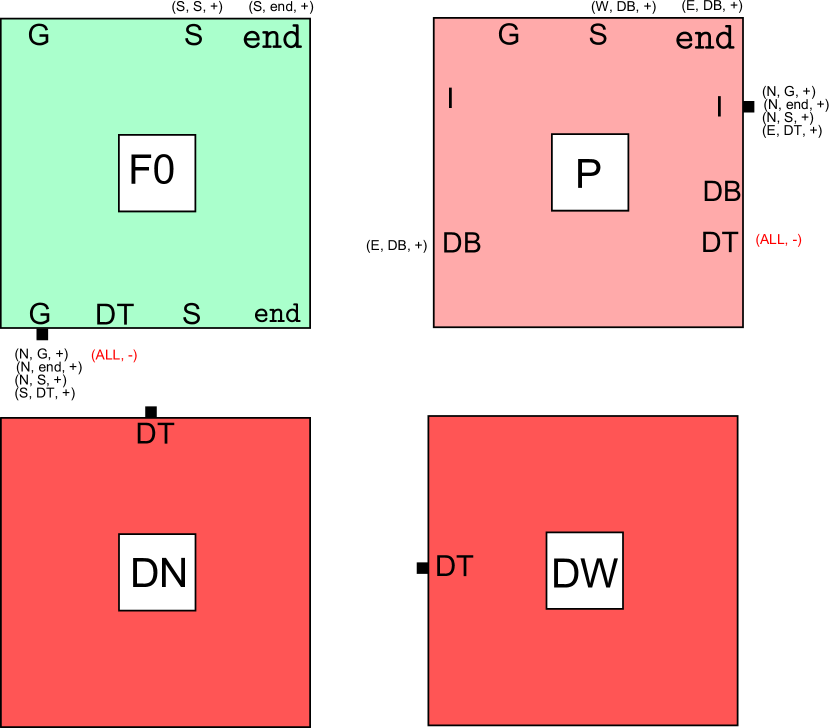
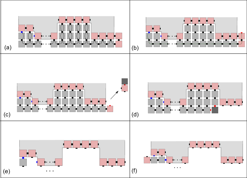
Figure 56 shows a schematic which gives a high level overview of how a southern perimeter path dissociates (note that all perimeter paths dissociate the same up to rotation). During the growth of the perimeter path and filler tiles, glues with the label are activated on all filler and path tiles except the filler tiles which bind to the perimeter path tiles. These tiles are shown in green in part (a) of Figure 56. In these tiles, a glue is activated on their east side. The position of the glue is such that the glue always appears on the input side of the tile (the side of the tile which has a glue that allows the tile to bind to the assembly). This means that as the path is growing around the perimeter, the glue on any tile is not exposed. In this case, we design the filler tiles so that they bind with strength (the temperature of the system) to the south side of the substage assembly. Section 6.1 explores the potential downfalls of this and explains why they are not a problem. If the system being designed has , we use the mechanism shown in Figure 54 to bind the filler tiles to the south side of the substage assembly with strength . Similar to the previous case, the binding of the westernmost southern end glue to a tile in the perimeter path triggers a cascade of signals in the perimeter path. Eventually, this cascade of signals causes the tile bound to the southernmost western end glue, to expose a glue as shown in part (b) of Figure 56 where the glue is depicted as a red glue. This allows a tile which only exposes a glue (and has no other glues), to bind to the exposed glue. Upon binding, the glue deactivates all glues on the tile except itself. Once this tile detaches, it exposes a glue on the next tile. This process is shown in parts (c) and (d) of Figure 56. Note that this case differs from the previous case in that during this process, the filler tiles do not dissociate. Recall that this is because the filler tiles which bind to the perimeter path tiles do not have glues activated. Eventually, the only tiles left on the south side of the substage assembly are the filler tiles as shown in part (e) of Figure 56. Once the connection glue is activated, a cascade of signals is activated as shown in part (f) of Figure 56 and is propagated by the tiles shown in green and the perimeter tiles of the substage assembly via the glue. Receiving this signal causes the green filler tiles to detach and deactivate all of their glues. Note that a tile binds to westernmost green filler tile which we call in part (g) of Figure 56. This prevents from exposing a glue which if activated, would deactivate all of its glues. Also, this glue could trigger a glue on a substage assembly which would have unintended consequences. Consequently, we design this tile so that it never separates from . Furthermore, the tile which binds to the west of serves as a starting point for the growth of perimeter path for the west side of the substage assembly. Now, a path of tiles grows from the tile and binds to the westernmost southern end glue . This propagates a signal back to the tile and allows for the tile to its west to begin the growth of the perimeter path on the west side of the substage assembly as shown in part (h) of Figure 53. When this occurs, the tiles above in the same column receive a signal which causes them to deactivate their glues. Now, the same process repeats on the west side of the substage assembly.
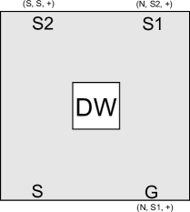
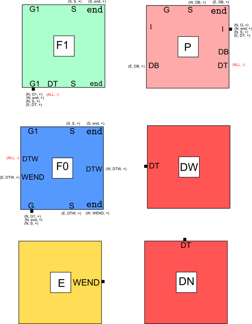
Note that while the description of mechanisms here were focused on dissociating the perimeter path and filler tiles on the south side of the substage assembly, these mechanisms can be easily adapted for any side of the substage assembly by rotating the tiles discussed here. Also note that while both of the scenarios we consider above examine the hard case where the south west corner of the substage assembly is a concave corner, the tile set can easily be adapted to handle the case where the corner is convex.
Every tile that we added will eventually have either a glue activated or a glue activated. Since both of these glues deactivate all other glues on the tile (with the potential exception of themselves), eventually, all of the tiles will become inert or the tile will be bound to the tile which has a single glue and will not expose any glues. Thus, we need only ensure that the binding of glues to the glues in the queue to be deactivated is benign. First, note that it follows from the construction of the tiles above that no tiles can bind to “non-static” glues (that is, glues which trigger an event) on any substage assemblies. Also, note that by the design of the tiles, the tiles could not unintentionally “link” two stages by exposing glues so that two separate stages could bind. Consequently, the only glues the glues in the queue to be deactivated can bind to are glues which will eventually detach and do not cause any binding events to occur within the glues of on a substage assembly. It follows that the tiles which have dissociated cannot interfere with the proper growth of substage assemblies.

6.3 Correctness of supertile bindings
We now discuss the geometric and timing constraints of substage connections. The key insight is that the connection glue is exposed only once a tooth and gap are present. To see this, an overview of the substage connection process is shown in Figure 46. As shown in the Figure, the tooth tile sends a signal which causes the connection glue (shown as green in Figure 46) to be exposed. This means that the connection glue cannot be exposed until the tooth tile is present. Also, the attachment of the tooth tile eventually causes a tile to fall off to make a gap on the side as shown in Figure 46. Once this occurs, another substage can attach via the connection glue. Then, and only then, is a signal sent which causes the filler tiles to dissociate.
Another important insight is that the filler tiles are present when the tooth tile attaches and remain present until after another substage has attached. The presence of filler tiles makes the side of the substage completely “flat” with the exception of a gap and tooth. This means, that only the same substages can attach to one another since exactly those substages have the tooth and gap in the same location. All other substages have their gaps and tooth tiles in different places relative to the connection glue which means they are geometrically prevented from binding.
7 Conclusion
In this paper, we have shown how signal-passing tiles can be designed to self-assemble discrete self-similar fractals in a very hierarchical manner. That is, separately and in parallel, the copies of each stage of a given fractal self-assemble, and then those copies combine to form the next stage. During this process, the sides of each copy which must combine with each other are prepared for that combination in such a way that only copies of the same stage can combine, and only once all pieces of the previous stage have attached. This is done by using geometric hindrance created by small bumps and dents at carefully spaced locations, along with well-controlled timing of glue activations. Once copies of a stage have bound together, any “filler” tiles which attached to create the necessary geometry along the combining edge, but which are not part of the final fractal shape, then detach. These detached tiles, called “junk”, are designed so that they always eventually become subassemblies which are no greater than size 2, and they cannot interfere with any additional assembly.
While these results allow for the self-assembly of fractals without any increase in scale factor and, for an infinite set of fractals, at temperature 1, there remain a number of improvements which may be possible and open questions which remain. First, is the cooperativity of temperature 2 strictly necessary for fractals which are not singly concave? I.e., is there a temperature 1 construction which can correctly self-assemble such fractals? It appears that such a construction would require non-trivial adaptations to or departures from our current construction. Conversely, proving it impossible also appears to be difficult. Second, can the maximum size of the terminal junk assemblies be reduced to the optimal value of 1? This also appears difficult due to the fact that within the STAM glue deactivations (like activations) happen asynchronously, and therefore it is not possible to guarantee that both sides of a bound glue (i.e. the glues on the two adjacent edges of bound tiles) have been deactivated before a tile or subassembly detaches. To counter problems that may arise from this, we frequently ensure that special “blocker” tiles first attach to the soon-to-be-junk tiles to hide glues which may not be off and which may allow the junk assembly to interfere with other supertiles. Third, is it possible to further reduce the number of junk assemblies which are produced, especially during the self-assembly of fractals such as the Sierpinski triangle, which in the current construction requires a number of tiles and junk assemblies on the order of approximately of the number of tiles which remain to form each given stage? Fourth, our construction for self-assembling the Sierpinski triangle in the proof of Theorem 4.1 uses 48 tile types (compared with 19 for the scale factor 2 version of jSignals ). Can this be reduced to a similar or smaller number?
References
- [1] K. Barth, D. Furcy, S. M. Summers, and P. Totzke. Scaled tree fractals do not strictly self-assemble. In Unconventional Computation & Natural Computation (UCNC) 2014, University of Western Ontario, London, Ontario, Canada July 14-18, 2014, pages 27–39, 2014.
- [2] S. Cannon, E. D. Demaine, M. L. Demaine, S. Eisenstat, M. J. Patitz, R. T. Schweller, S. M. Summers, and A. Winslow. Two hands are better than one (up to constant factors): Self-assembly in the 2ham vs. atam. In N. Portier and T. Wilke, editors, STACS, volume 20 of LIPIcs, pages 172–184. Schloss Dagstuhl - Leibniz-Zentrum fuer Informatik, 2013.
- [3] C. T. Chalk, D. A. Fernandez, A. Huerta, M. A. Maldonado, R. T. Schweller, and L. Sweet. Strict self-assembly of fractals using multiple hands. Algorithmica, pages 1–30, 2015.
- [4] Q. Cheng, G. Aggarwal, M. H. Goldwasser, M.-Y. Kao, R. T. Schweller, and P. M. de Espanés. Complexities for generalized models of self-assembly. SIAM Journal on Computing, 34:1493–1515, 2005.
- [5] E. D. Demaine, M. L. Demaine, S. P. Fekete, M. Ishaque, E. Rafalin, R. T. Schweller, and D. L. Souvaine. Staged self-assembly: nanomanufacture of arbitrary shapes with glues. Natural Computing, 7(3):347–370, 2008.
- [6] T. Fochtman, J. Hendricks, J. E. Padilla, M. J. Patitz, and T. A. Rogers. Signal transmission across tile assemblies: 3D static tiles simulate active self-assembly by 2D signal-passing tiles. Technical Report 1306.5005, Computing Research Repository, 2013.
- [7] J. Hendricks, M. Olsen, M. J. Patitz, T. A. Rogers, and H. Thomas. Hierarchical self-assembly of fractals with signal-passing tiles (extended abstract). In Proceedings of the 22nd International Conference on DNA Computing and Molecular Programming (DNA 22), Ludwig-Maximilians-Universität, Munich, Germany September 4-8, 2016, pages 82–97.
- [8] J. Hendricks, M. Olsen, M. J. Patitz, T. A. Rogers, and H. Thomas. Hierarchical self-assembly of fractals with signal-passing tiles. Technical Report 1606.01856, Computing Research Repository, 2016.
- [9] J. Hendricks, M. J. Patitz, and T. A. Rogers. Replication of arbitrary hole-free shapes via self-assembly with signal-passing tiles (extended abstract). In C. S. Calude and M. J. Dinneen, editors, Unconventional Computation and Natural Computation - 14th International Conference, UCNC 2015, Auckland, New Zealand, August 30 - September 3, 2015, Proceedings, volume 9252 of Lecture Notes in Computer Science, pages 202–214. Springer, 2015.
- [10] N. Jonoska and D. Karpenko. Active tile self-assembly, part 1: Universality at temperature 1. International Journal of Foundations of Computer Science, 25(02):141–163, 2014.
- [11] N. Jonoska and D. Karpenko. Active tile self-assembly, part 2: Self-similar structures and structural recursion. International Journal of Foundations of Computer Science, 25(02):165–194, 2014.
- [12] A. Keenan, R. Schweller, and X. Zhong. Exponential replication of patterns in the signal tile assembly model. Natural Computing, 14(2):265–278.
- [13] J. I. Lathrop, J. H. Lutz, and S. M. Summers. Strict self-assembly of discrete Sierpinski triangles. Theoretical Computer Science, 410:384–405, 2009.
- [14] J. H. Lutz and B. Shutters. Approximate self-assembly of the sierpinski triangle. Theory Comput. Syst., 51(3):372–400, 2012.
- [15] J. E. Padilla, M. J. Patitz, R. T. Schweller, N. C. Seeman, S. M. Summers, and X. Zhong. Asynchronous signal passing for tile self-assembly: Fuel efficient computation and efficient assembly of shapes. International Journal of Foundations of Computer Science, 25(4):459–488, 2014.
- [16] J. E. Padilla, R. Sha, M. Kristiansen, J. Chen, N. Jonoska, and N. C. Seeman. A signal-passing dna-strand-exchange mechanism for active self-assembly of dna nanostructures. Angewandte Chemie International Edition, 2015.
- [17] M. J. Patitz and S. M. Summers. Self-assembly of discrete self-similar fractals. Natural Computing, 1:135–172, 2010.
- [18] E. Winfree. Algorithmic Self-Assembly of DNA. PhD thesis, California Institute of Technology, June 1998.