Molecular Dynamics Simulations of Compression-Tension Asymmetry in Plasticity of Fe Nanopillars
Abstract
Tension-compression asymmetry is a notable feature of plasticity in bcc single crystals. Recent experiments reveal striking differences in the plasticity of bcc nanopillars for tension and compression. Here we present results from molecular dynamics simulations of nanopillars of bcc Fe in tension and compression. We find that a totally different deformation mechanism applies in each cases: dislocation glide in compression and twinning in tension. This difference explains experimentally-observed asymmetry in the nanopillar morphology.
keywords:
Nanopillar , Plasticity , Molecular Dynamics , Dislocations , Twinning1 Introduction
The development of micro-mechanical testing on single crystals [1] has enabled the study of plastic deformation to be taken to the microscopic level. Under uniaxial compression of single crystals, yield can be observed on a single slip plane. Samples can now be tested in both tension and compression, and there is a marked contrast between the shear banding in compression and twinning observed in tension[2]. Recent work has shifted to bcc materials, where again asymmetry is observed.
For dislocation motion, FCC materials generally obey Schmidt’s law: a dislocation moves once the shear stress on its glide plane exceeds a critical magnitude. Thus Schmidt’s law predicts identical behaviour under tension and compression. By contrast, BCC materials typically do not obey Schmidt’s law: dislocation behaviour depending on stresses outside the slip plane. This can be traced to the core structure of dislocations.
Recent experiments by Kim and Greer revealed a tension-compression asymmetry in the plasticity of bcc nanopillars [3, 4, 5, 6]. In compression, they observe plastic deformation confined mostly to narrow slip bands, and stress vs strain behaviour characterised by many strain bursts. This stress vs. strain signature would suggest deformation by dislocation nucleation and motion. In tension they observe necking, and the stress vs strain behaviour revealed larger periods of almost constant flow stress. Kim and Greer suggested that the twinning-antitwinning asymmetry could be a cause for the compression-tension asymmetry[3]. However, their experiments cannot determine what processes were occurring at the atomic level. Molecular dynamics simulations can be used to study such atomic level processes.
The dependence of the critical resolved shear stress (CRSS) on the sense of shear (i.e. tension or compression) is a feature of bcc single crystals [7, 8, 9]. Initial explanations for this phenomenon focused on twinning-antitwinning slip asymmetry. type twins in bcc crystals can be viewed as dislocations split into fractional dislocations which spread out on subsequent planes to create a twin plane [10]. The movement of these fractional dislocations is only permitted in one direction on a given axis in order to create a twin boundary. Glide in the opposite direction (the anti-twinning direction) creates an unstable stacking fault which is not a twin plane. The CRSS for glide of fractional dislocations in the twinning direction is therefore lower.
Work by Vitek et al gives further weight to this argument[11, 12]: In this study, the gamma surface for a plane was calculated using a Finnis-Sinclair potential, and an asymmetry in the direction was found. For a crystal in a fixed orientation, relative motion of subsequent slip planes in compression will always be in the opposite direction to relative motion of subsequent slip planes in tension. The directional asymmetry in the glide of dislocations is consequently thought to result in a compression-tension asymmetry for single crystals [11, 8, 3, 4, 5]. Further study[11, 13, 14] revealed another mechanism for CRSS dependence on the sense of shear. Molecular dynamics calculations showed that the core structure of dislocations in bcc materials was altered by non-glide shear stresses. Due to a three-fold symmetry in the core structure of screw dislocations in bcc, the change in the core structure depends on the direction of the shear stress. Unlike the twinning-antitwinning asymmetry, these changes in the core structure affect slip on all slip planes, not just glide on planes.
Previous molecular dynamics studies of plasticity in nanopillars of bcc Fe have focused on tensile strains. Observed plasticity mechanisms for tension have varied, with some studies reporting deformation by dislocations and phase transitions while others report deformation by twinning. These differences in plasticity behaviour may be due to a number of factors, including the potentials used and differing pillar geometries. In particular, the value for the difference in energy per atom between the fcc and bcc phase of the material can differ significantly across different potentials. Using a potential where this energy value is low may result in a tendency for bcc Fe to change to fcc in certain parts of the system under the influence of an applied stress or strain. The crystallographic orientation of the surfaces of the pillars may also affect the simulation results. It is energetically favourable for bcc structures such as nanopillars to have low energy surfaces. Pillars containing high energy surfaces may have a tendency to deform in a way which allows surface reconstructions to occur as reported by Ackland in fcc nanopillars [15]. The direction of the compression or tension could also affect the plasticity behaviour as the tendency to observe dislocation glide in a material depends on the schmidt factors for the slip planes in the pillars and these schmidt factors in turn depend on the direction of the applied strain. Here we offer a brief overview of previous molecular dynamics studies of plasticity in Fe nanopillars.
Zhang et al [16] performed simulations of tensile strain of nanopillars oriented along and directions. The pillars contained type side surfaces and the pillars contained two and two type side surfaces. Deformation was observed to occur by dislocation glide in the pillar and by a phase transformation from bcc to fcc in the pillars. This dependence of plasticity behaviour on pillar geometry may be due to the different crystallographic surface orientations in the side faces of these two pillars as well as differing schmidt factors for slip planes in each pillar. The potential used in this study was one for Fe developed by Mishin et al [17]. For this potential, the difference in energy per atom between the fcc and bcc phases is 50 meV [17]. This value is lower than calculated in many ab initio calculations which typically give values between 70 meV and 120 meV [18, 19, 20, 21].
Simulations of tensile strain of bcc Fe nanowires were also carried out by Sandoval and Urbassek [22]. They constructed pillars oriented along with a circular cross section. In this study deformation was found to occur by a phase tranformation from fcc to a combination of fcc and hcp. The potential used in this study was one for Fe developed by Meyer and Entel [23]. The energy difference in energy per atom between the fcc and bcc phases is 40 meV for this potential [18, 23] which is again rather low in comparison to values calculated in ab initio calculations.
Li et al [24] performed simulations of tensile strain on pillars with type side surfaces. Deformation was found to occur by twinning. The potential used in this study was one developed by Mendelev et al[19] for which the difference in energy per atom between the fcc and bcc phases is 120 meV.
The phase transitions observed in the simulations by Zhang et al and Sandoval and Urbassek are most likely the result of using potentials with low values for the difference in energy per atom between the fcc and bcc phases. This is evidenced by the lack phase transitions in the simulations by Li et al. In this study, we use a modified version of the Mendelev et al potential as the difference in energy per atom between the fcc and bcc phases lies within the range of values typically found from ab initio calculations. We construct nanopillars containing low energy type side surfaces to avoid possible surface reconstructions which could occur in order to generate low energy surfaces on the pillars as the strain is applied.
One might speculate that the observed tension-compression asymmetry in bcc nanopillars is related to the intrinsic non-Schmidt behaviour of the dislocations. Alternately, one might argue that the mechanism should be the same as for fcc materials. Here we use molecular dynamics simulations to simulate the tension-compression asymmetry in nanopillars of bcc Fe. We show that the asymmetry is due to different deformation mechanisms: dislocation glide in compression and twinning in tension. For completeness, we also examine fcc nanopillars and find no such effect.
2 Simulation Details
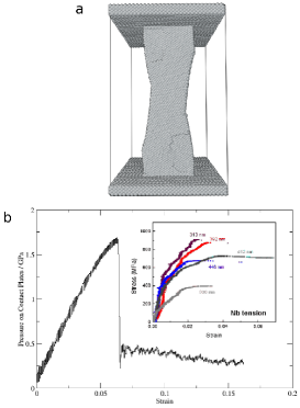
Our system consisted of a pillar with a square cross-section in between two ”indenter plates” as seen in figure 1(a). The pillars had approximate dimensions of 5.85.815.4 nm and contained 45513 atoms. The sample is confined by the indenter plates, each containing 9901 atoms (12.1 nm 12.1 nm 0.9 nm). Movement of indenter plate atoms is constrained in order to apply external forces. The side faces of the pillar were type faces and the pillars were compressed in the [001] direction. It is necessary to have faces on the pillar as these are the lowest energy surfaces. Creating a pillar with higher energy surfaces will result in recrystallization during the simulation and this has been shown to have create spurious deformation behaviour[15].
Prior to loading, all pillars were heated to 300K by running a simulation for 50 picoseconds with a Nosé-Hoover thermostat[25, 26]. Uniaxial strain was applied by moving the indenter plates and rescaling the atomic coordinates in the direction of loading by 0.05% at 2 picosecond intervals. The resulting strain rate is 2.5 . This method of compressing the system, by rescaling the coordinates of the atoms in the compression direction, is required so that a shock wave is not produced in the pillar. Since the thickness of the pillar may change through the simulation, “stress” on the sample is not easily defined: we measure the force required to hold the indenter plate in position, converted to a stress by dividing by the indenter area. Simulations were carried out using the MOLDY molecular dynamics code[15]. The potential function used was that developed by Hepburn and Ackland [27].
3 Results
3.1 Compression
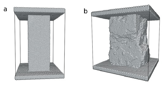
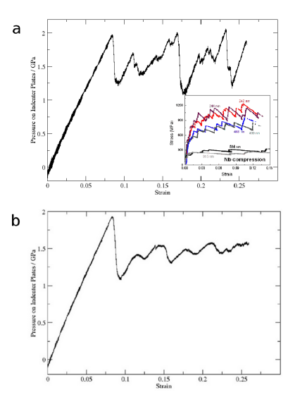
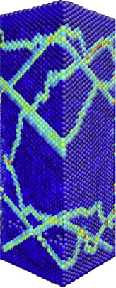
Under compressive strain-loading, deformation in the pillars was mediated mainly by dislocation glide. Dislocations are created at the surfaces of the pillars when the stress is high and move quickly through the pillar. Typically, dislocations form at corners, which allows them to be short but requires a mixed edge-screw character. This gives characteristic bursts of deformation leading to sudden decreases in stress, as can be seen in the graph in figure 2(a). Each sudden drop in pressure on the indenter plate happens when a dislocation is created and moves through the pillar, creating a discrete strain burst. This behaviour is qualitatively similar to stress vs strain signatures obtained by Kim et al[5] in experimental studies of nanopillars of Nb, which can be seen in figure 2 (b). Each dislocation slip event creates a step on the surface of the pillar. Figure 1(b) shows an image of a pillar following a strain of 26%. Many steps in the surface of the pillar due to dislocation glide activity can be seen in this figure.
Initially, the flat side surfaces provide the only nucleation sites, and yield depends on dislocation nucleation from perfect side surfaces. At the initial yield corresponding to the first peak in figure 2(a), several dislocations are nucleated simultaneously. Subsequent yield events generally involve the nucleation and glide of a single dislocation.
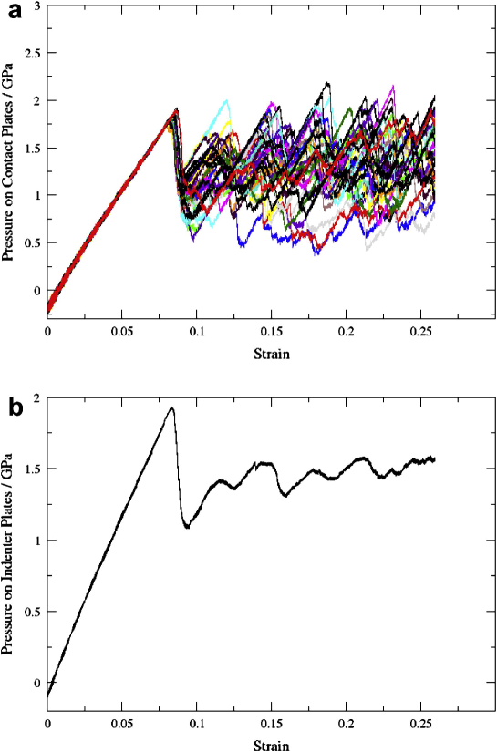
To whether this sequence of discrete yield events is deterministic or random, we repeated the compression simulation 60 times. In all simulations the first dislocation creation event occurs at an indenter pressure of 2GPa and at a strain of about 7.5%. Many dislocations are created almost simultaneously at this point, and the drop in stress varies by a factor of 2. The stress then builds elastically to a second yield event. Subsequent dislocation creation and glide events occur stochastically within a range of indenter pressure values and at varied values of strain. This is illustrated by figure 3. Figure 3 (a) shows plots of indenter plate pressure vs strain for 60 different simulations superimposed on one graph. From this graph, it can be seen that the indenter plate pressure and strain values at the initial yield point are the same for all simulation runs. These values are distributed at random for subsequent dislocation glide events. This interpretation is confirmed by the average indenter plate pressure vs strain graph shown in figure 3 (b) which shows the pressure on the indenter plates at various strain values averaged over the 60 different pillar compression simulations. Averaged over many simulation runs, the indenter plate pressure approaches an approximately constant value at large strain due to the random positions of the stress peaks associated with each dislocation glide event.
Comparing with nanopillar experiments we see similar bursts of deformation: in our strain controlled simulations this manifests as a sharp drop in stress at fixed strain, whereas under stress control the same mechanism would give sharp increase in strain at fixed stress. The experimental boundary conditions mix stress and strain control, hence the same mechanism manifests as simultaneous strain increase and stress drop. The lower stresses required to initiate subsequent bursts is due to the roughening of the pillar having lowered the potential energy barrier for dislocation creation at the surface.
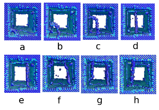
The sequence of images in figure 4 shows a typical occurrence of dislocation glide. dislocations are created at the corners of the pillars. Initially the dislocation lines are curved and have a mixed edge/screw character. As the dislocation lines grow in length the dislocation line becomes straight and the dislocation has pure screw character. Each dislocation glides on many different planes as a high degree of cross slip occurs. The dislocations continue to glide and cross-slip along the direction of highest shear stress until they reach one of the pillar surfaces, where they leave a step behind. The process then repeats.
3.1.1 Dislocation Geometry
The compression mechanism is clearly dislocation-based. Using the dislocation extraction algorithm (DXA) developed by Stukowski and Albe [30] we find that all dislocations have Burgers vectors. Dislocations could also be identified by measuring centrosymmetry of nearest and second nearest neighbours of atoms with respect to the atom in question. A numerical measure of this central symmetry can be found using the centrosymmetry parameter defined by Kelchner et al [31].
3.1.2 Atomic Shear Strain Analysis and Slip Planes
Atomic strain tensor analysis shows that a significant amount of cross slip occurs in the sample under compression. Slip was found to occur on a series of connected planes for each dislocation. Figure 5 shows a cross section of the pillar following a compressive strain of 14%. Atoms are coloured according to the local atomic shear strain metric as defined by Shimizu et al [32]. Cross sectional slices were taken across two faces of the pillar and the viewing direction is a direction which runs diagonally through the centre of the pillar. Atoms coloured light blue and green have high local atomic shear strains and are located on slip planes on which dislocation glide has occurred. The jagged profile of these slip plane atoms indicates that a significant amount of cross slip has occurred. Closer inspection of the slip plane atoms reveals that their profile is jagged on one side of the pillar and generally straight on the other side. This is due to the orientation of the dislocations being perfect straight screw dislocations as seen in figure 4. The straight lines formed by the dislocation lines were always parallel to one of the side faces of the pillar and therefore the slip path cross sections seen in figure 5 must always be straight on one face of the pillar cross section even when a significant amount of cross slip has occurred. Cross slip allows many dislocations to traverse a path which runs at approximately to the direction of compression. The dislocations cross-slip so as to travel in this direction of maximum shear stress.
3.2 Tension
We have also carried out simulations on pillars in tension, and found that deformation occurs by twinning.
This is consistent with the mechanism whereby partial dislocations with burgers vector move on successive planes creating a twin boundary on a plane[10] as reported in similar molecular dynamics simulation recently by Li et al [24]. However, in our simulations the twin formation is very rapid, and it is not possible to identify individual fractional dislocation events.
A typical image of a pillar following a tensile strain of 16% is shown in fig 6. Twin formation occurred in a single event - as shown in the massive yield event at 6% strain in 6(b). After the initial yield event, twinning deformation proceeds by motion of the twin boundary in a continuous process as shown by the plot of indenter plate pressure vs strain in figure 6(b). A large stress is required to create the twins initially, but the strain subsequently continues at an almost continuous stress level as the twin boundaries move. The asymptotic stress is lower than that required for compression by a factor of 3: more than can be accounted for by changes in the cross-sectional area. With the exception of the initial stress peak in 6(b), this stress vs strain behaviour is qualitatively similar to the stress vs strain signature recorded in experiments on nanopillars of Nb reported by Kim et al[5] which can be seen in figure 6(b, inset). The initial stress peak observed in our simulations is probably due to the high strain rates which we are limited to in molecular dynamics simulations.
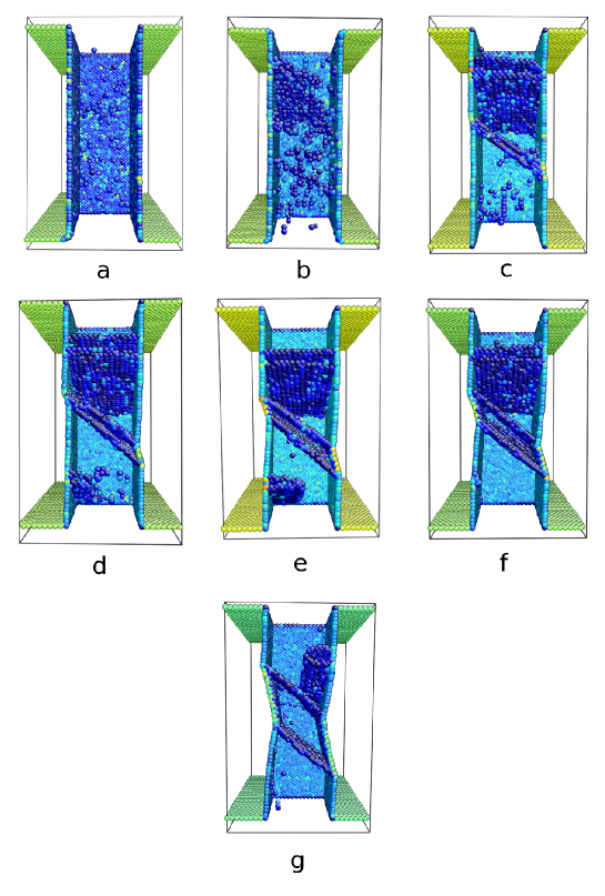
The sequence of images in figure 7 shows the creation of pairs of twin boundaries during the tensile strain simulation. When the pillar first begins to deform plastically, three pairs of twin boundaries are created. As the separation between the twins in the middle of the pillar grows, the other two pairs of twins shrink in size to allow the central twins to move.
It should be noted that this twinning process results in the creation of surfaces on the pillar in the plastically deformed region in the centre. These surfaces are unstable and our nanosample will recrystallize if held at this strain and allowed to relax. Alternately, if the stress is removed the sample will untwin in order to reduce the surface energy. In a sense, this nanopillar exhibits superplasticity. To study the deformation, we worked at shear rates where these diffusive reconstructions did not occur. This is consistent with previous MD calculations. Suppressing these reconstruction events is justifiable because the driving force for them is the dominant effect of surface energy, something which is only the case at the nanoscale, and not in pillars of the size considered in experiment.
3.3 FCC materials
We have tested the plasticity behaviour for fcc Cu nanopillars and have found little differences between plasticity behaviour in compression and tension. Deformation in these pillars occurred through partial dislocation glide on planes, without any cross slip occurring, for both tension and compression. The yield stress in tension for these pillars was about half that in compression. This is consistent with previous reports of MD simulations of plasticity in copper [33, 34].
4 Discussion
Under compression, our Fe pillars deform by glide of dislocations on slip planes. Under tension a twinning mechanism operates. This is consistent with much experimental evidence including that of Kim and Greer [3, 4, 5, 6] which showed bursts of dislocation motion punctuated by periods of rising stress.
There are some differences in the behaviour between our MD simulations and experimental results, due to differences in boundary conditions. Experimental results for compression of bcc nanopillars often reveal strain bursts in the stress vs strain behaviour. In contrast we see a series of sudden stress drops. This apparent difference is because we apply fixed strain, which means that events involving large spontaneous strain are impossible. There may be some difference due to the small size of our pillars, the high strain rates which we have to work with in MD: in particular the surface-driven recrystallization may well be a size effect. The experimental boundary conditions are difficult to characterize: although nominally under stress control, they actually show large sudden changes both in stress and strain.
In the tensile case, the twinning we observe is a possible mechanism by which the necking seen in Kim and Greer’s experiments could occur. The long periods of constant flow stress observed in these experiments agrees well with that seen in simulations as seen in figure 6. The biggest difference between simulations and experiment in this case is the large initial stress required to nucleate the twin in our simulations. This is because unlike the experiments we have an atomically-flat surface, on a dislocation free sample. Such high yield stresses are observed in experiments with dislocation-free single-crystal whiskers.
A possible explanation for the observed asymmetry comes from the fact that dislocation cores in bcc are spread in three dimensions. The more compact the core, the easier it is for the dislocation to move. Hence, under compression, the core will be compacted, favouring the dislocation mechanism, while under tension the core can spread even further, making dislocation motion more difficult[11, 13, 14].
The twinning-antitwinning asymmetry is not present in fcc crystals as formation of twins is not mediated by fractional dislocations as in bcc materials. The change in the core structure under stress in bcc materials is dependent on the presence of edge components in fractional dislocations[11]. Due to the lack of fractional dislocations in fcc materials, this effect is not observed in fcc materials.
5 Conclusion
In bcc nanopillars, the deformation mechanism is completely different in compression and tension. This asymmetry is not present in fcc nanopillars.
In the compressive case, plastic deformation is mediated by dislocations. Plastic deformation occurs in discrete bursts when one or more dislocations are created at the pillar surfaces and move through the pillar by glide. A large amount of cross slip is observed in this deformation regime allowing for the dislocations to move in the direction of maximum shear stress. By contrast, in the tensile case deformation occurs through the creation and motion of twin boundaries. This is consistent with asymmetry observed in various experiments.
References
- Uchic et al. [2004] Uchic MD, Dimiduk DM, Florando JN, Nix WD. Sample dimensions influence strength and crystal plasticity. Science 2004;305(5686):986–9.
- Jang et al. [2012] Jang D, Li X, Gao H, Greer JR. Deformation mechanisms in nanotwinned metal nanopillars. Nat Nano 2012;7(9):594–601.
- Kim and Greer [2009] Kim JY, Greer JR. Tensile and compressive behavior of gold and molybdenum single crystals at the nano-scale. Acta Materialia 2009;57(17):5245 –53.
- Kim et al. [2012] Kim JY, Jang D, Greer JR. Crystallographic orientation and size dependence of tension–compression asymmetry in molybdenum nano-pillars. International Journal of Plasticity 2012;28(1):46 – 52.
- Kim et al. [2010] Kim JY, Jang D, Greer JR. Tensile and compressive behavior of tungsten, molybdenum, tantalum and niobium at the nanoscale. Acta Materialia 2010;58(7):2355 –63.
- Kim et al. [2009] Kim JY, Jang D, Greer JR. Insight into the deformation behavior of niobium single crystals under uniaxial compression and tension at the nanoscale. Scripta Materialia 2009;61(3):300 –3.
- Taylor and Elam [1926] Taylor GI, Elam CF. The distortion of iron crystals. Proceedings of the Royal Society of London Series A 1926;112(761):337–61.
- Christian [1983] Christian J. Some surprising features of the plastic deformation of body-centered cubic metals and alloys. Metallurgical and Materials Transactions A 1983;14:1237–56.
- Hollang et al. [1997] Hollang L, Hommel M, Seeger A. The flow stress of ultra-high-purity molybdenum single crystals. physica status solidi (a) 1997;160(2):329–54.
- Hull [1985] Hull D. Introduction to Dislocations. 1 ed.; Pergamon Press; 1985.
- Duesbery and Vitek [1998] Duesbery M, Vitek V. Plastic anisotropy in b.c.c. transition metals. Acta Materialia 1998;46(5):1481 –92.
- Ito and Vitek [2001] Ito K, Vitek V. Atomistic study of non-schmid effects in the plastic yielding of bcc metals. Philosophical Magazine A 2001;81(5):1387–407.
- Groger et al. [2008] Groger R, Racherla V, Bassani J, Vitek V. Multiscale modeling of plastic deformation of molybdenum and tungsten: Ii. yield criterion for single crystals based on atomistic studies of glide of screw dislocations. Acta Materialia 2008;56(19):5412 –25.
- Groger and Vitek [2008] Groger R, Vitek V. Multiscale modeling of plastic deformation of molybdenum and tungsten. iii. effects of temperature and plastic strain rate. Acta Materialia 2008;56(19):5426 –39.
- Ackland et al. [2011] Ackland G, D’Mellow K, Daraszewicz S, Hepburn D, Uhrin M, Stratford K. The moldy short-range molecular dynamics package. Computer Physics Communications 2011;182(12):2587 –604.
- [16] Y. Zhang, D.J. Yu, K.M. Wang J Mater Sci Technol, 28 (2) (2012), pp. 164–168
- [17] Y. Mishin, M.J. Mehl, D.A. Papaconstantopoulos Acta Mater, 53 (15) (2005), pp. 4029–4041
- [18] C. Engin, L. Sandoval, H.M. Urbassek Modell Simul Mater Sci Eng, 16 (3) (2008), p. 035005
- Mendelev et al. [2003] Mendelev M, Hans S, Srolovitz D, Ackland G, Sun D, Asta M. Development of new interatomic potentials appropriate for crystalline and liquid iron. Phil Mag 2003;83:3977–94.
- [20] J. Zhu, X.W. Wang, S.G. Louie Phys Rev B, 45 (1992), pp. 8887–8893
- [21] C. Amador, W.R.L. Lambrecht, B. Segall Phys Rev B, 46 (1992), pp. 1870–1873
- [22] L. Sandoval, H.M. Urbassek Nanotechnology, 20 (32) (2009), p. 325704
- [23] R. Meyer, P. Entel Phys Rev B, 57 (1998), pp. 5140–5147
- Li et al. [2010] Li S, Ding X, Deng J, Lookman T, Li J, Ren X, et al. Superelasticity in bcc nanowires by a reversible twinning mechanism. Phys Rev B 2010;82:205435.
- Nose [1984] Nose S. A unified formulation of the constant temperature molecular dynamics methods. The Journal of Chemical Physics 1984;81(1):511–9.
- Hoover [1985] Hoover WG. Canonical dynamics: Equilibrium phase-space distributions. Phys Rev A 1985;31:1695–7.
- Hepburn and Ackland [2008] Hepburn DJ, Ackland GJ. Metallic-covalent interatomic potential for carbon in iron. Phys Rev B 2008;78:165115.
- Li [2003] Li J. Atomeye: an efficient atomistic configuration viewer. Modelling and Simulation in Materials Science and Engineering 2003;11(2):173.
- Stukowski [2010] Stukowski A. Visualization and analysis of atomistic simulation data with ovito–the open visualization tool. Modelling and Simulation in Materials Science and Engineering 2010;18(1):015012.
- Stukowski and Albe [2010] Stukowski A, Albe K. Extracting dislocations and non-dislocation crystal defects from atomistic simulation data. Modelling and Simulation in Materials Science and Engineering 2010;18(8):085001.
- Kelchner et al. [1998] Kelchner CL, Plimpton SJ, Hamilton JC. Dislocation nucleation and defect structure during surface indentation. Phys Rev B 1998;58:11085–8.
- [32] F. Shimizu, S. Ogat, J. Li Mater Trans, 48 (2007), 2923–2927
- Brown and Ghoniem [2010] Brown J, Ghoniem N. Reversible–irreversible plasticity transition in twinned copper nanopillars. Acta Materialia 2010;58(3):886 –94.
- Li and Ghoniem [2009] Li L, Ghoniem NM. Twin-size effects on the deformation of nanotwinned copper. Phys Rev B 2009;79:075444.