Thermoelectric performance of spin Seebeck effect in Fe3O4/Pt-based thin film heterostructures
Abstract
We report a systematic study on the thermoelectric performance of spin Seebeck devices based on Fe3O4/Pt junction systems. We explore two types of device geometries: a spin Hall thermopile and spin Seebeck multilayer structures. The spin Hall thermopile increases the sensitivity of the spin Seebeck effect, while the increase in the sample internal resistance has a detrimental effect on the output power. We found that the spin Seebeck multilayers can overcome this limitation since the multilayers exhibit the enhancement of the thermoelectric voltage and the reduction of the internal resistance simultaneously, therefore resulting in significant power enhancement. This result demonstrates that the multilayer structures are useful for improving the thermoelectric performance of the spin Seebeck effect.
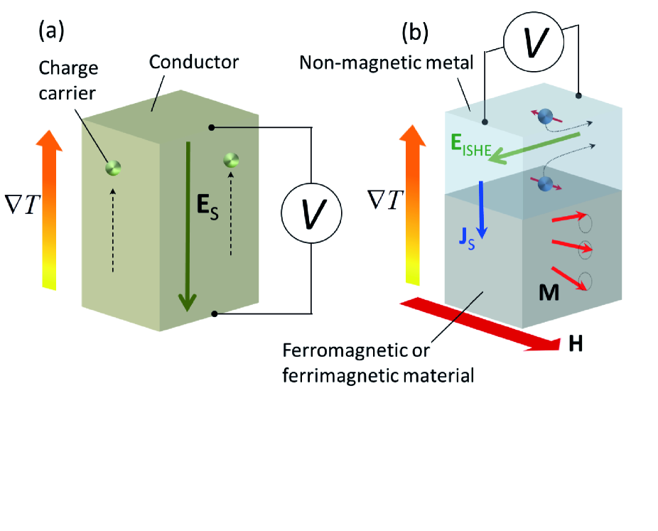
Thermoelectrics is one of the promising energy harvesting technologies for waste heat management and recovery, having potential applications in thermoelectric generation or temperature sensing. Thermoelectric generation usually relies on the Seebeck effect, a phenomenon that refers to the generation of an electromotive force parallel to the direction of an applied temperature gradient in electrically conducting materials [see Fig. 1(a)].
In spintronics,Wolf et al. (2001); Žutić
et al. (2004) a different thermoelectric principle was recently discovered. The principle is based on a spin counterpart of the Seebeck effect, in analogy named the spin Seebeck effect (SSE).Uchida et al. (2008) The SSE refers to the generation of spin currents Maekawa et al. (2013) in a ferromagnetic material (F) upon application of a temperature gradient. The spin current induced by the SSE is injected into a non-magnetic metal (N) in contact with F and converted into an electromotive force by means of the inverse spin Hall effect (ISHE) in suitable N materialsSaitoh et al. (2006); Valenzuela and Tinkham (2006); Kimura et al. (2007); Costache et al. (2006) [Fig. 1(b)]. The SSE has been observed in a range of ferromagnetic materials: metals,Uchida et al. (2008) semiconductors Jaworski et al. (2010, 2011) and insulators.Uchida et al. (2010a); Meier et al. (2013); Niizeki et al. (2015) Thus, the SSE has been experimentally established as a general transport phenomenon in ferromagnets. Since the discovery of the SSE, the study of the interaction among spin, charge, and heat currents has been strongly invigorated, which is the main focus of spin caloritronics.Bauer et al. (2012); Boona et al. (2014) This has resulted in the discovery of various thermospin effects, such as the spin Peltier effect Flipse et al. (2014) and the spin dependent versions of the ordinary Seebeck Slachter et al. (2010) and Peltier Flipse et al. (2012) effects among others.Le Breton et al. (2011); Yu et al. (2010); An et al. (2013)
Theoretically, the SSE Xiao et al. (2010); Adachi et al. (2011, 2013) is understood as an effect resulting from the thermal non-equilibrium between magnons in F and conduction electrons in N, generating a spin current at the F/N interface proportional to the effective temperature difference between magnons in F and electrons in N. Theories from other view points have also been developed,Hoffman et al. (2013); Zhang and Zhang (2012); Rezende et al. (2014) where roles of magnon spin currents inside the ferromagnet has been highlighted.Zhang and Zhang (2012); Rezende et al. (2014) This is supported by several recent experiments: the dependence of SSE voltage with the thickness of F,Kehlberger et al. (2015) the enhancement of the SSE voltage in magnetic multilayers,Ramos et al. (2015) and the suppression of the SSE at high magnetic fields.Kikkawa et al. (2015); Jin et al. (2015)
The SSE has potential advantages over conventional thermoelectric technologies for thermal energy harvesting. The experimental geometry, having paths for heat and electric currents independent and perpendicular to each other, allows to have two different materials that can be optimised independently and it is also advantageous for the implementation of thin film devices over large surfaces, for example, simply by thin film coating.Kirihara et al. (2012) Moreover, the observation of the SSE in magnetic insulators implies the potential to generate pure spin currents with lesser dissipation losses due to mobile charge carriers and further expanding the range of possible materials where spin mediated thermoelectric conversion can be studied. However, a main disadvantage of the SSE is the low magnitude of the thermoelectric output. Strategies to overcome this limitation are currently being explored. One possibility is to increase the spin current detection efficiency by taking advantage of the spin Hall angle characteristics of different N materials,Liu et al. (2012); Pai et al. (2012); Niimi et al. (2012); Laczkowski et al. (2014) as it has been shown in the spin Hall thermopiles.Uchida et al. (2012) A different approach can be directed towards increasing the thermal spin current generation, as recently shown in the SSE of magnetic multilayers.Ramos et al. (2015)
In this paper, we have investigated the thermoelectric performance of two types of SSE devices: spin Hall thermopiles Uchida et al. (2012) and magnetic multilayers formed by repeated growth of number of [F/N] bilayers, hereafter referred to as [F/N]n. We have performed room temperature measurements of the thermoelectric voltage and power output characteristics for both the structures. The materials chosen to form the basic F/N bilayer structure are magnetite, Fe3O4, as the F layer and platinum, Pt, as the N layer. Magnetite is a ferrimagnetic oxide, commonly employed in spintronicsWolf et al. (2001); Žutić
et al. (2004) due to its half-metallic character and high Curie temperature.Dedkov et al. (2002); Walz (2002) These properties have inspired several studies of its magnetotransport properties.Li et al. (1998); Ramos et al. (2008, 2014); Wu et al. (2010, 2012) Platinum is a material commonly used for spin current detection, due to its relatively large spin Hall angle.Hoffmann (2013); Sinova et al. (2015)
The Fe3O4 films were grown on magnesium oxide, MgO(001), substrates by pulsed laser deposition using a KrF excimer laser with 248 nm wavelength, 10 Hz repetition rate, and 3 109 W/cm2 irradiance in an ultrahigh-vacuum chamber (UHV). The Pt films were deposited in the same UHV chamber by DC magnetron sputtering. Further details on the growth can be found in Ref. 47. The film thickness was measured by x-ray reflectivity and its structural quality was confirmed by x-ray diffraction and transmission electron microscopy (TEM). The film cross sections were prepared by Focused Ion Beam and measured by high angle annular dark field (HAADF) scanning transmission electron microscopy (STEM). The measurements were carried out in a probe aberration corrected FEI Titan 60-300 operated at 300 kV. The fabrication of the spin Hall thermopile structure was carried out using optical lithography, following a two-step process consisting of Ar milling of the Fe3O4/Pt bilayer and fabrication of Al interconnection wires by metal evaporation and lift-off.
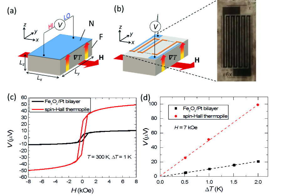
The SSE experiments were performed using the longitudinal configuration.Uchida et al. (2010b) The sample dimensions are = 2 mm, = 7 mm and = 0.5 mm, except for the spin Hall thermopile structure in which the in plane sample geometry is defined by the lithography pattern. Figure 2(a) shows a schematic illustration of the longitudinal SSE measurement geometry. The sample is placed between two AlN plates with high thermal conductivity, where the top plate has a resistive heater and the lower plate works as a heat sink. By passing an electric current to the heater, a temperature gradient () is applied in the direction. This generates a temperature difference () between the bottom and top of the sample, which are stabilized at temperatures and , respectively. All the measurements were carried out at = 300 K. The temperature difference is monitored by two thermocouples connected differentially. The SSE voltage in the Pt film is measured along the direction with a nanovoltmeter, while a magnetic field is applied in the direction.
The measurement mechanism is as follows. In the longitudinal configuration, a spin current is injected into the Pt layer with the spatial direction perpendicular to the Fe3O4/Pt interface (parallel to ) and the spin-polarization vector (parallel to the magnetization of Fe3O4). Then, an electric field () is generated in Pt due to the ISHE, which can be expressed as:
| (1) |
where and denote the spin Hall angle and electric resistivity of Pt, respectively. By measuring the voltage between the ends of the Pt film, we can electrically detect the SSE by means of the ISHE as . Although the longitudinal configuration is widely used to measure the SSE in ferrimagnetic insulators, in samples with electrically conductive F layers there can be an additional contribution of the anomalous Nernst effect (ANE) in itinerant ferromagnets.Ramos et al. (2014) Since Fe3O4 is electrically conductive at room temperature, we need to evaluate the contribution from the ANE of the Fe3O4 film to the measured SSE voltage in the Fe3O4/Pt system. We have previously shown that by considering simple equivalent circuit model,Ramos et al. (2013) the following expression can be obtained: , which gives the electric field in the Fe3O4/Pt bilayer as a function of the ANE-induced electric field () and the shunting parameter , with () and () being the resistivity and thickness of the Pt (Fe3O4) layer, respectively. In the case of the Fe3O4/Pt system, the ANE of the Fe3O4 film is strongly suppressed due to the fact that the resistivity of Fe3O4 is two orders of magnitude greater than that of Pt. For instance, in the Fe3O4/Pt bilayer with = 50 nm and = 5 nm, used for the spin Hall thermopile, we obtained that the ANE signal in the Fe3O4/Pt bilayer is reduced to 10 % of the ANE in a Fe3O4 single film. This gives a contribution from the ANE of the Fe3O4 film to the SSE measured in the Fe3O4/Pt bilayer system, which is of only about 2 % of the measured voltage. Therefore, the SSE dominates the thermoelectric voltage in our Fe3O4/Pt systems.
First, we show the SSE in the spin Hall thermopile structure in comparison to that in a single Fe3O4/Pt bilayer. In analogy to thermopile structures commonly used in conventional thermoelectric modules, where the output voltage is increased by connecting a number of thermocouple junctions of materials with dissimilar Seebeck coefficients electrically in series and thermally in parallel,Snyder and Toberer (2008) the spin Hall thermopiles improve the electrical detection of the SSE by enhancing the ISHE voltage. This is achieved by using two materials with different spin Hall angles. These are placed alternatively on top of the ferromagnet forming an array and connected in series forming a zig-zag structure [see Fig. 2(b)].
In this study, we fabricated the spin Hall thermopile comprising a set of 6 parallel Fe3O4/Pt wires. The wires were formed by patterning the Fe3O4/Pt bilayer film. This is due to the fact that the ANE suppression depends on the relative resistance values between the Fe3O4 and Pt layers, therefore we cannot deposit an array of Pt wires on a plain Fe3O4 film, as the Pt wires will become comparatively more resistive and the ANE contribution, with respect to the Fe3O4/Pt bilayer, will change. The Fe3O4/Pt wires are then electrically connected in series forming a zig-zag structure using a metal with negligible spin Hall angle Hoffmann (2013) and therefore no ISHE contribution (130 nm of Al in our case). In this spin Hall thermopile, the SSE signal is generated by the Fe3O4/Pt wires and the Al wires are only used for electrical connection. The width of the Fe3O4/Pt and Al wires are 200 m and 100 m, respectively and their length is 5 mm except for the rightmost and leftmost Fe3O4/Pt wires, which have a length of 6 mm including electrode pads [see Fig. 2(b) for an optical image of the thermopile].
Figure 2(c) shows the comparative results for the field dependence of the transversal voltage for the single Fe3O4/Pt bilayer sample and the Fe3O4/Pt spin Hall thermopile at = 1 K. We clearly observe a strong enhancement of the SSE voltage in the spin Hall thermopile, as expected from the series connection of the Fe3O4/Pt elements, effectively increasing the length of the sample. Figure 2(d) shows at = 7 kOe as a function of , thus confirming the linear dependence between and . From the slope of these curves we can extract the magnitude of the SSE thermopower of the single bilayer sample and spin Hall thermopile, obtaining the values of 10 V/K and 50 V/K, respectively. The SSE voltage per one Fe3O4/Pt wire in the spin Hall thermopile is estimated to be 8.2 V/K and a value of the electric field per unit temperature difference (/) of 1.6 mV/Km is obtained. This value is consistent with the electric field (/) measured in the Fe3O4/Pt bilayer, therefore, showing that the increase in voltage is proportional to the increase in the effective length of the sample. The thermoelectric voltage of the spin Hall thermopile can be further enhanced by increasing the integration density of wires.Uchida et al. (2012)
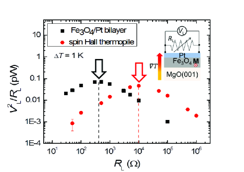
The electric power output characteristics of the SSE in the Fe3O4/Pt single bilayer and spin Hall thermopile were also investigated. This is performed by attaching a variable load resistance () to the samples and measuring the voltage drop across , as schematically shown in the inset of Fig. 3. Then, we estimate the output power as /. Figure 3 shows the comparative results obtained for the single bilayer and spin Hall thermopile as a function of ; the output power is maximized when equals the internal resistance of the sample, as expected from impedance-matching criterion for maximum power transfer and also in agreement with previous reports.Uchida et al. (2014) We can see that, despite the increased voltage response in the spin Hall thermopile structure, there is no advantage in terms of extractable electrical power output from the device when compared to the response of the single Fe3O4/Pt bilayer. This is a consequence of the fact that the voltage enhancement is due to the increase in effective length of the sample, which is associated to an increase in the internal resistance.Uchida et al. (2014)
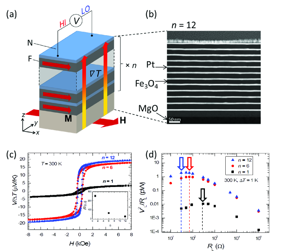
In the case of ANE-based thermopile structures Sakuraba et al. (2013) it was proposed that, if the ANE voltage is independent of sample thickness, the performance can be improved by reducing the internal resistance of the devices, by just increasing the ferromagnet thickness. However, this approach cannot be used in the case of spin Hall thermopiles, since increasing the thickness of the N layers will result in a reduction of the ISHE voltage Kikkawa et al. (2013). Therefore, in order to increase the electric output power of the SSE, we must follow a different approach. To realize the enhancement of the output power of the SSE, we have investigated the thermoelectric performance of the SSE multilayers ([F/N]n) formed by repeated growth of number of F/N bilayers [Fig. 4(a)]. This type of structure has recently been reported to present an enhancement of the transversal thermoelectric voltage in various magnetic multilayer systems based on oxide/metal,Ramos et al. (2015) all-metallic,Lee et al. (2015); Uchida et al. (2015) and all-oxide Shiomi et al. (2015) junctions. The advantage of the multilayer structure is that along with the voltage enhancement, the internal resistance of the structure decreases with increasing the layer number, due to parallel connection between the layers. Therefore, a significant enhancement of the extractable electric power is expected.
Here, we show the measured results of voltage and output power characteristics of the SSE in [Fe3O4(23)/Pt(7)]n multilayer structures, with = 1, 6 and 12. The structural quality of the multilayers was confirmed by TEM. A STEM-HAADF image of the [Fe3O4/Pt]12 multilayer shows well defined interfaces [see Fig. 4(b)]. As shown in Fig. 4(c), the voltage in the multilayer structure with = 6 and 12 presents an enhancement of about one order of magnitude in comparison with that in the single bilayer with = 1. The observed enhancement of the SSE voltage in the Fe3O4/Pt multilayer systems can be explained as a result of an increase in the thermally generated spin current flowing across the multilayers.Ramos et al. (2015) This enhancement can be measured due to the presence of Pt interlayers that detect the spin current enhancement within the multilayer. Importantly, since the resistance of the multilayer decreases with increasing the number of the Fe3O4/Pt layers [see inset of Fig 4(c)], it is expected that the power as well as voltage is enhanced. The power output characteristics of the multilayer samples are shown in Fig. 4(d). We found that the power largely increases in the multilayer systems, reaching more than two orders of magnitude enhancement compared to the single bilayer case: the power is estimated to be 0.01, 1 and 2 pW/K2 for = 1, 6 and 12, respectively.
In summary, we have performed thermoelectric voltage and power measurements of the spin Hall thermopile and SSE multilayer structures based on Fe3O4/Pt junction systems. Our results show that the spin Hall thermopile can enhance the voltage, but cannot improve the power output due to the increase of the internal resistance of the devices. However, the voltage increase is beneficial to increase the sensitivity of the SSE and might have possible sensor applications. In contrast, the multilayer SSE devices significantly enhance both thermoelectric voltage and power compared to the conventional bilayer systems, leading to an efficiency improvement in SSE-based thermoelectric generation. Although the obtained power is still small, we believe that the SSE in multilayers can be further enhanced by careful choice of materials and device geometry. Since the observed SSE enhancement in multilayers is expected to depend on spin transport properties across the multilayers, using materials with longer spin transport characteristic lengths might lead to further enhancement in the SSE.
The authors thank S. Maekawa, H. Adachi, T. Kikkawa, J. Shiomi, T. Oyake, A. Kirihara, and M. Ishida for valuable discussions. The microscopy works were conducted in the Laboratorio de Microscopías Avanzadas at Instituto de Nanociencia de Aragón, Universidad de Zaragoza. This work was supported by the Spanish Ministry of Science (through projects PRI-PIBJP-2011-0794, MAT2011-27553-C02, including FEDER funding), the Aragón Regional Government (project E26), Thermo-spintronic Marie-Curie CIG (Grant Agreement No. 304043), JST-PRESTO “Phase Interfaces for Highly Efficient Energy Utilization” from JST, Japan, Grant-in-Aid for Scientific Research on Innovative Areas “Nano Spin Conversion Science” (26103005), Grant-in-Aid for Challenging Exploratory Research (26600067), Grant-in-Aid for Scientific Research (A) (15H02012) from MEXT, Japan, NEC Corporation, and The Noguchi Institute.
References
- Wolf et al. (2001) S. A. Wolf, D. D. Awschalom, R. A. Buhrman, J. M. Daughton, S. von Molnár, M. L. Roukes, A. Y. Chtchelkanova, and D. M. Treger, Science 294, 1488 (2001).
- Žutić et al. (2004) I. Žutić, J. Fabian, and S. Das Sarma, Rev. Mod. Phys. 76, 323 (2004).
- Uchida et al. (2008) K. Uchida, S. Takahashi, K. Harii, J. Ieda, W. Koshibae, K. Ando, S. Maekawa, and E. Saitoh, Nature 455, 778 (2008).
- Maekawa et al. (2013) S. Maekawa, H. Adachi, K. Uchida, J. Ieda, and E. Saitoh, J. Phys. Soc. Jpn. 82, 102002 (2013).
- Saitoh et al. (2006) E. Saitoh, M. Ueda, H. Miyajima, and G. Tatara, Appl. Phys. Lett. 88, 182509 (2006).
- Valenzuela and Tinkham (2006) S. O. Valenzuela and M. Tinkham, Nature 442, 176 (2006).
- Kimura et al. (2007) T. Kimura, Y. Otani, T. Sato, S. Takahashi, and S. Maekawa, Phys. Rev. Lett. 98, 156601 (2007).
- Costache et al. (2006) M. V. Costache, M. Sladkov, S. M. Watts, C. H. van Der Wal, and B. J. van Wees, Phys. Rev. Lett. 97, 216603 (2006).
- Jaworski et al. (2010) C. M. Jaworski, J. Yang, S. Mack, D. D. Awschalom, J. P. Heremans, and R. C. Myers, Nat Mater 9, 898 (2010).
- Jaworski et al. (2011) C. M. Jaworski, J. Yang, S. Mack, D. D. Awschalom, R. C. Myers, and J. P. Heremans, Phys. Rev. Lett. 106, 186601 (2011).
- Uchida et al. (2010a) K. Uchida, J. Xiao, H. Adachi, J. Ohe, S. Takahashi, J. Ieda, T. Ota, Y. Kajiwara, H. Umezawa, H. Kawai, et al., Nat. Mater. 9, 894 (2010a).
- Meier et al. (2013) D. Meier, T. Kuschel, L. Shen, A. Gupta, T. Kikkawa, K. Uchida, E. Saitoh, J.-M. Schmalhorst, and G. Reiss, Physical Review B 87, 054421 (2013).
- Niizeki et al. (2015) T. Niizeki, T. Kikkawa, K. Uchida, M. Oka, K. Z. Suzuki, H. Yanagihara, E. Kita, and E. Saitoh, AIP Advances 5, 053603 (2015).
- Bauer et al. (2012) G. E. W. Bauer, E. Saitoh, and B. J. van Wees, Nat. Mater. 11, 391 (2012).
- Boona et al. (2014) S. R. Boona, R. C. Myers, and J. P. Heremans, Energy Environ. Sci. 7, 885 (2014).
- Flipse et al. (2014) J. Flipse, F. K. Dejene, D. Wagenaar, G. E. W. Bauer, J. B. Youssef, and B. J. V. Wees, Phys. Rev. Lett. 113, 027601 (2014).
- Slachter et al. (2010) A. Slachter, F. L. Bakker, J.-P. Adam, and B. J. van Wees, Nat. Phys. 6, 879 (2010).
- Flipse et al. (2012) J. Flipse, F. L. Bakker, a. Slachter, F. K. Dejene, and B. J. van Wees, Nat. Nanotechnol. 7, 166 (2012).
- Le Breton et al. (2011) J.-C. Le Breton, S. Sharma, H. Saito, S. Yuasa, and R. Jansen, Nature 475, 82 (2011).
- Yu et al. (2010) H. Yu, S. Granville, D. P. Yu, and J.-P. Ansermet, Phys. Rev. Lett. 104, 146601 (2010).
- An et al. (2013) T. An, V. I. Vasyuchka, K. Uchida, A. V. Chumak, K. Yamaguchi, K. Harii, J. Ohe, M. B. Jungfleisch, Y. Kajiwara, H. Adachi, et al., Nat. Mat. 12, 549 (2013).
- Xiao et al. (2010) J. Xiao, G. E. W. Bauer, K. Uchida, E. Saitoh, and S. Maekawa, Phys. Rev. B 81, 214418 (2010).
- Adachi et al. (2011) H. Adachi, J.-i. Ohe, S. Takahashi, and S. Maekawa, Phys. Rev. B 83, 094410 (2011).
- Adachi et al. (2013) H. Adachi, K. Uchida, E. Saitoh, and S. Maekawa, Rep. Prog. Phys. 76, 036501 (2013).
- Hoffman et al. (2013) S. Hoffman, K. Sato, and Y. Tserkovnyak, Phys. Rev. B 88, 064408 (2013).
- Zhang and Zhang (2012) S. S.-L. Zhang and S. Zhang, Phys. Rev. B 86, 214424 (2012).
- Rezende et al. (2014) S. M. Rezende, R. L. Rodríguez-Suárez, R. O. Cunha, A. R. Rodrigues, F. L. A. Machado, G. A. Fonseca Guerra, J. C. Lopez Ortiz, and A. Azevedo, Phys. Rev. B 89, 014416 (2014).
- Kehlberger et al. (2015) A. Kehlberger, U. Ritzmann, D. Hinzke, E.-J. Guo, J. Cramer, G. Jakob, M. C. Onbasli, D. H. Kim, C. A. Ross, M. B. Jungfleisch, et al., Phys. Rev. Lett. 115, 096602 (2015).
- Ramos et al. (2015) R. Ramos, T. Kikkawa, M. H. Aguirre, I. Lucas, A. Anadón, T. Oyake, K. Uchida, and H. Adachi, Phys. Rev. B 92, 220407(R) (2015).
- Kikkawa et al. (2015) T. Kikkawa, K. Uchida, S. Daimon, Z. Qiu, Y. Shiomi, and E. Saitoh, Phys. Rev. B 92, 064413 (2015).
- Jin et al. (2015) H. Jin, S. R. Boona, Z. Yang, R. C. Myers, and J. P. Heremans, Phys. Rev. B 92, 054436 (2015).
- Kirihara et al. (2012) A. Kirihara, K. Uchida, Y. Kajiwara, M. Ishida, Y. Nakamura, T. Manako, E. Saitoh, and S. Yorozu, 11, 686 (2012).
- Liu et al. (2012) L. Liu, C.-F. Pai, Y. Li, H. W. Tseng, D. C. Ralph, and R. A. Buhrman, Science 336, 555 (2012).
- Pai et al. (2012) C.-F. Pai, L. Liu, Y. Li, H. W. Tseng, D. C. Ralph, and R. A. Buhrman, Appl. Phys. Lett. 101, 122404 (2012).
- Niimi et al. (2012) Y. Niimi, Y. Kawanishi, D. H. Wei, C. Deranlot, H. X. Yang, M. Chshiev, T. Valet, A. Fert, and Y. Otani, Phys. Rev. Lett. 109, 156602 (2012).
- Laczkowski et al. (2014) P. Laczkowski, J.-C. Rojas-Sánchez, W. Savero-Torres, H. Jaffrès, N. Reyren, C. Deranlot, L. Notin, C. Beigné, a. Marty, J.-P. Attané, et al., Appl. Phys. Lett. 104, 142403 (2014).
- Uchida et al. (2012) K. Uchida, T. Nonaka, T. Yoshino, T. Kikkawa, D. Kikuchi, and E. Saitoh, Appl. Phys. Express 5, 093001 (2012).
- Dedkov et al. (2002) Y. S. Dedkov, U. Rüdiger, and G. Güntherodt, Phys. Rev. B 65, 64417 (2002).
- Walz (2002) F. Walz, J. Phys.: Condens. Matter 14, R285 (2002).
- Li et al. (1998) X. W. Li, a. Gupta, G. Xiao, W. Qian, and V. P. Dravid, Appl. Phys. Lett. 73, 3282 (1998).
- Ramos et al. (2008) R. Ramos, S. K. Arora, and I. V. Shvets, Phys. Rev. B 78, 214402 (2008).
- Ramos et al. (2014) R. Ramos, M. H. Aguirre, A. Anadón, J. Blasco, I. Lucas, K. Uchida, P. A. Algarabel, L. Morellón, E. Saitoh, and M. R. Ibarra, Physical Review B 90, 054422 (2014).
- Wu et al. (2010) H.-C. Wu, M. Abid, B. S. Chun, R. Ramos, O. N. Mryasov, and I. V. Shvets, Nano Lett. 10, 1132 (2010).
- Wu et al. (2012) H.-C. Wu, R. Ramos, R. G. S. Sofin, Z.-M. Liao, M. Abid, and I. V. Shvets, Appl. Phys. Lett. 101, 052402 (2012).
- Hoffmann (2013) A. Hoffmann, IEEE Trans. Magn. 49, 5172 (2013).
- Sinova et al. (2015) J. Sinova, S. O. Valenzuela, J. Wunderlich, C. Back, and T. Jungwirth, Rev. Mod. Phys. 87, 1213 (2015).
- Orna et al. (2010) J. Orna, P. A. Algarabel, L. Morellón, J. A. Pardo, J. M. de Teresa, R. López Antón, F. Bartolomé, L. M. García, J. Bartolomé, J. C. Cezar, et al., Phys. Rev. B 81, 144420 (2010).
- Uchida et al. (2010b) K. Uchida, H. Adachi, T. Ota, H. Nakayama, S. Maekawa, and E. Saitoh, Appl. Phys. Lett. 97, 172505 (2010b).
- Ramos et al. (2013) R. Ramos, T. Kikkawa, K. Uchida, H. Adachi, I. Lucas, M. H. Aguirre, P. Algarabel, L. Morellón, S. Maekawa, E. Saitoh, et al., Appl. Phys. Lett. 102, 072413 (2013).
- Snyder and Toberer (2008) G. J. Snyder and E. S. Toberer, Nat. Mat. 7, 105 (2008).
- Uchida et al. (2014) K. Uchida, M. Ishida, T. Kikkawa, A. Kirihara, T. Murakami, and E. Saitoh, J. Phys.: Condens. Matter 26, 343202 (2014).
- Sakuraba et al. (2013) Y. Sakuraba, K. Hasegawa, M. Mizuguchi, T. Kubota, S. Mizukami, T. Miyazaki, and K. Takanashi, Appl. Phys. Express 6, 033003 (2013).
- Kikkawa et al. (2013) T. Kikkawa, K. Uchida, S. Daimon, Y. Shiomi, H. Adachi, Z. Qiu, D. Hou, X.-F. Jin, S. Maekawa, and E. Saitoh, Phys. Rev. B 88, 214403 (2013).
- Lee et al. (2015) K.-D. Lee, D.-J. Kim, H. Yeon Lee, S.-H. Kim, J.-H. Lee, K.-M. Lee, J.-R. Jeong, K.-S. Lee, H.-S. Song, J.-W. Sohn, et al., Sci. Rep. 5, 10249 (2015).
- Uchida et al. (2015) K. Uchida, T. Kikkawa, T. Seki, T. Oyake, J. Shiomi, K. Takanashi, and E. Saitoh, Phys. Rev. B 92, 094414 (2015).
- Shiomi et al. (2015) Y. Shiomi, Y. Handa, T. Kikkawa, and E. Saitoh, Appl. Phys. Lett. 106, 232403 (2015).