Multi-Connectivity in 5G mmWave Cellular Networks
Abstract
The millimeter wave (mmWave) frequencies offer the potential of orders of magnitude increases in capacity for next-generation cellular wireless systems. However, links in mmWave networks are highly susceptible to blocking and may suffer from rapid variations in quality. Connectivity to multiple cells – both in the mmWave and in the traditional lower frequencies – is thus considered essential for robust connectivity. However, one of the challenges in supporting multi-connectivity in the mmWave space is the requirement for the network to track the direction of each link in addition to its power and timing. With highly directional beams and fast varying channels, this directional tracking may be the main bottleneck in realizing robust mmWave networks. To address this challenge, this paper proposes a novel measurement system based on (i) the UE transmitting sounding signals in directions that sweep the angular space, (ii) the mmWave cells measuring the instantaneous received signal strength along with its variance to better capture the dynamics and, consequently, the reliability of a channel/direction and, finally, (iii) a centralized controller making handover and scheduling decisions based on the mmWave cell reports and transmitting the decisions either via a mmWave cell or conventional microwave cell (when control signaling paths are not available). We argue that the proposed scheme enables efficient and highly adaptive cell selection in the presence of the channel variability expected at mmWave frequencies.
Index Terms:
5G, millimeter wave, multi-connectivity, initial access, handover.I Introduction
The millimeter wave (mmWave) bands – roughly above 10 GHz – have attracted considerable attention for micro- and picocellular systems [1]. These frequencies offer much more bandwidth than current cellular allocations in the congested bands below 3 GHz, and initial capacity estimates have suggested that networks with mmWave cells can offer orders of magnitude greater capacity than state-of-the-art 4G systems [2].
However, one of the challenges in designing cellular networks in the mmWave bands is robustness, and one likely key feature of mmWave cellular networks that can improve robustness is multi-connectivity (MC) [3]. MmWave signals are blocked by many common building materials such as brick, and the human body can also significantly attenuate signals in the mmWave range [4]. Thus, the communication quality between the user equipment (UE) and any one cell can be highly variable as the movement of obstacles or even the changing position of the body relative to the mobile device can lead to rapid drops in signal strength. Multi-connectivity is a feature in which each UE maintains multiple possible signal paths to different cells so that drops in one link can be overcome by switching data paths. In mmWave networks, this multi-connectivity can be both among multiple mmWave cells as well as between 5G mmWave cells and traditional 4G cells below 3 GHz, with the low frequency cells offering greater robustness but lower bandwidth.
This paper addresses one of the key challenges in supporting multi-connectivity in heterogeneous networks (HetNets) with mmWave cells, namely directional multi-cell channel tracking and measurement reports. Multi-connectivity is already supported as part of carrier aggregation – one of the most important features in 3GPP LTE-Advanced [5]. In standard carrier aggregation, the network maintains power and timing information of the UE at multiple cells and can then schedule data on the optimal link. However, multi-connectivity is significantly more complicated at mmWave, primarily because transmissions are likely to be highly directional. Thus, in addition to power and timing tracking, the network and UE must constantly monitor the direction of transmission of each potential link. Tracking changing directions can slow the rate at which the network can adapt and can be a major obstacle in providing robust service in the face of variable link quality. In addition, the UE and the base station (BS) may only be able to listen to one direction at a time, thus making it hard to receive the control signaling necessary to switch paths.
To address this challenge, this paper proposes a novel multi-cell measurement reporting system where each UE directionally broadcasts a sounding reference signal (SRS) in a time-varying direction that continuously sweeps the angular space. Each potential serving cell scans all its angular directions and monitors the strength of the received SRS along with its variance, to better capture the dynamics of the channel. A centralized controller obtains complete directional knowledge from all the potential cells in the network to make the optimal serving cell selection and scheduling decision. We argue that this scheme has the three important features listed below.
Directional uplink measurements: Importantly, unlike in traditional LTE channel aggregation, the proposed system is based on the channel quality of uplink (UL) rather than downlink (DL) signals. We argue that this has several key benefits. First, the use of UL signals eliminates the need for the UE to send measurement reports back to the network and thereby removes a point of failure in the control signaling path. Second, we show that if digital beamforming or beamforming with multiple analog streams is available at the mmWave cell, then the directional scan time can be dramatically reduced when using UL-based measurements. Finally, since the base station is less power constrained than a mobile device, digital or hybrid beamforming will likely be more feasible at the BS side.
Capturing channel variance: Additionally, by updating the variance of the per user received signal strength at each iteration, we are able to better capture the dynamics of the channel and bias the cell selection strategy of delay-sensitive applications towards more robust cells.
Enhanced control signaling: A key issue in implementing control for mmWave multi-connectivity is directionality. Specifically, if the UE is using analog beamforming it may only be able to “listen” in one direction at a time. Hence, if the network switches the serving cell (handover), the new serving cell may not be able to communicate the switch to the UE. To circumvent this problem, we propose that the network be able to send scheduling and serving cell decisions of the mmWave cells over the legacy microwave cells, in the case when the mmWave links are not available. Control signaling can be used to implement more efficient resource allocation on initial access strategies.
The rest of the paper is organized as follows. In Section II, we describe the multi-cell measurement procedure. In Section III, we report some examples of how this framework can be used towards designing better control strategies. In Section IV, we provide some results and, finally, we conclude the paper and list some future research steps in Section V.
II Procedure Description
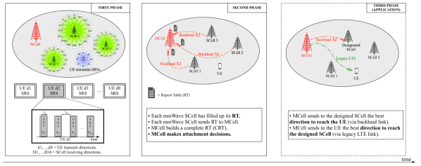
In the proposed framework, illustrated in Figure 1, there is one major node called MCell (Master Cell, in accordance with 3GPP LTE terminology), which here is typically a microwave base station. However, functionally, the MCell can be any network entity that performs centralized handover and scheduling decisions. The UE may receive data from a number of cells, either mmWave or microwave, and we call each such cell an SCell (Secondary Cell). In order to communicate and exchange control information, the SCells and the MCell are inter-connected via traditional backhaul X2 interface connections, while each user can be reached by its serving MCell through the legacy 4G-LTE band.
MmWave SCells and UE will likely utilize directional phase arrays for transmission. In this work, we will assume that nodes select one of a finite number of directions, and we let and be the number of directions at each BS and UE, respectively. Thus, between any cell and the UE there are a total of direction pairs. The key challenge in implementing multi-cell connectivity is that the network must, in essence, monitor the signal strength on each of the directions pairs for each of the possible links. This is done by each SCell building a report tables (RT), based on the channel quality of each receiving direction, per each user. Our proposed method performs this monitoring through the following three phases.
II-1 Phase 1: Uplink measurements
The UE directionally broadcasts uplink sounding reference signals in dedicated slots, steering through directions , one at a time, to cover the whole angular space. The SRSs are scrambled by locally unique identifiers (e.g., C-RNTI) that are known to the SCells. Each SCell performs an exhaustive search, scanning through directions,111In the case of digital beamforming, the receiver would detect the signal strength from all directions in a single slot. in order to fill the row of the report table, which refers to the user steering direction . The quantity
| (1) |
represents the highest perceived SINR between the UE, transmitting through direction , and SCellj, maximized over all its possible receiving directions. The value
| (2) |
is the angular direction through which such was received by SCellj.
Each mmWave SCell keeps a record of previous RTs and updates, at each scan, the variance vari,j of the maximum SINR, . When, at scan , SCellj computes a new SINR value , according to (1), the variance is updated as:
| (3) | ||||
using the SINR values of the previously saved report tables.
If the base station has finite memory and can keep a record of just previous RT replicas, then the variance is updated as:
| (4) | |||
The uplink SRS signals could also be monitored by cells that are not currently SCells
to see if they should be added.
| UE direction | SCell1 | SCell2 | … | SCellM | |||||||||
| 1 |
|
|
… |
|
|||||||||
| 2 |
|
|
… |
|
|||||||||
| … | … | … | … | … | |||||||||
|
|
… |
|
II-2 Phase 2: Network decision
Once the RT of each SCell has been filled, each mmWave cell sends this information to the supervising microwave MCell through the backhaul link which, in turn, builds a complete report table (CRT), as depicted in Table I. When accessing the CRT, the MCell selects the best mmWave BS candidate for the considered user, based on different metrics. For example, the MCell could select the maximum SINR (with some hysteresis), in order to have the best channel propagation conditions, so
| (5) |
where is the direction the UE should set to obtain the maximum SINR and reach the mmWave SCell with ID . Such maximum SINR is associated, in the CRT’s entry, to the SCell direction , which should therefore be selected by the mmWave BS to reach the UE with the best performance.
II-3 Phase 3: Path switch and scheduling command
If the serving cell needs to be switched, or a secondary cell needs to be added or dropped, the MCell needs to inform both the UE and the cell. Since the UE may not be listening in the direction of the target SCell, the UE may not be able to hear a command from that cell. Moreover, since a common reason for the path switch and for cell additions in the mmWave regime are due to link failures, the control link to the serving mmWave cell may not be available either. To handle these circumstances, we propose that the path switch and scheduling commands be able to be communicated over the legacy 4G cell. Therefore, the MCell notifies the designated mmWave SCell (with ID ), via the high capacity backhaul, about the UE’s desire to attach to it. It also embeds the best direction that should be set to reach that user. Moreover, it sends to the UE, through an omnidirectional control signal at microwaves, the best user direction to select, to reach such candidate SCell. By this time, the best SCell-UE beam pair has been determined, therefore the transceiver can directionally communicate in the mmWave band.
III Control Applications for MC Procedure
The proposed UL-based framework can be used to address some of the most important 5G control plane challenges that arise when dealing with mmWave frequency bands. In this section, we list some of the functions that are suitable to be implemented with our MC procedure.
III-A Handover
Handover is performed when the UE moves from the coverage of one cell to the coverage of another cell [6]. Frequent handover, even for fixed UEs, is a potential drawback of mmWave systems due to their vulnerability to random obstacles, which is not the case in LTE. Dense deployments of short range BSs, as foreseen in mmWave cellular networks, may exacerbate frequent handovers between adjacent BSs. Loss of beamforming information due to channel change is another reason for handover and reassociation [7]. There are only a few papers on handover in mmWave 5G cellular [8, 9, 10, 11], since research in this field is just in its infancy.
Our proposed procedure exploits the centralized-MCell control over the network, which can be used to determine the UE optimal target mmWave SCell (and direction) to associate with, as illustrated in Figure 2, when the user is in connected-mode, i.e., it is already synchronized with both the macro and the mmWave cells. The key input information for the handover decision includes (i) instantaneous channel quality, (ii) channel variance, and (iii) cell occupancy.
Assume that a new RT is collected at the SCell side and forwarded to the MCell, after the proposed three-phase MC procedure has been completed. By accessing the table, if the optimal mmWave cell the user should associate to is different from the current one, then a handover should be triggered, to maximize the user SINR and rate222In order to reduce the handover frequency, more sophisticated decision criteria could be investigated, rather than triggering a handover every time a more suitable SCell is identified (i.e., the reassociation might be performed only if the SINR increases above a predefined threshold, with respect to the previous time instant). A more detailed discussion of the different handover paradigms is beyond the scope of this paper.. The use of both microwave and mmWave control planes is a key functionality for such an handover technique. In fact, in Phase 3, the handover decision is forwarded to the UE by the MCell, whose microwave link is much more robust and less volatile than its mmWave counterpart, thereby removing a point of failure in the control signaling path. Since each SCell periodically forwards the RT, the MCell has a complete overview of the cell dynamics and propagation conditions and can accordingly make handover decisions, to maximize the overall performance of the cell it oversees.
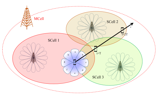
As an example, we refer to Figure 2. Suppose that, at time , the user is attached to SCell 1 and keeps moving in a fixed direction at constant speed . When, at time , the MCell collects a new CRT, it can decide whether or not to make the user perform a handover to another mmWave cell (i.e., SCell 3, if the highest SINR is no longer referred to SCell 1, meaning that the scenario has changed and a handover to another mmWave cell could increase the user’s QoS).
We finally remark that if previous versions of the report table are kept as a record, the MCell can also use the SCells variance in selecting the mmWave cell a user should attach to, after a handover is triggered. If a selected SCell shows a large variance (which reflects high channel instability), the user might need to handover again in the very near future. Therefore, it could be better to trigger a handover only to an SCell which grants both good SINR and sufficient channel stability, leading to a more continuous and longer-term association with such designated cell.
III-B Multi-Cell Initial Access
The procedure described in Sections II and III-A referred to a UE that is already connected to the network. However, we show that the uplink based control may be leveraged for fast initial access from idle mode. Initial access (IA) is the procedure by which a mobile UE establishes an initial physical link connection with a cell, a necessary step to access the network. In current LTE systems, IA is performed on omnidirectional channels [6]. However, in mmWave cellular systems, transmissions will need to be directional to overcome the increased isotropic pathloss experienced at higher frequencies. IA must thus provide a mechanism by which the BS and the UE can determine suitable initial directions of transmission.
MmWave IA procedures have been recently analyzed in [12, 13, 14, 15]. Different design options have been compared in [16] and [17], to evaluate coverage and access delay. We refer to [17] for a more detailed survey of recent IA works. All of these methods are based on the current LTE design where each cell broadcasts synchronization signals and the UE scans the directional space to detect the signals and base station cells to potentially connect to. We will call these “downlink” based designs, since the transmissions come from the BSs to the UEs. A key result of these findings is that the dominant delay in downlink-based IA arises in this initial sychronization phase.
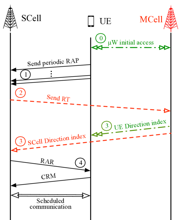
In this work, we propose an alternate “uplink” scheme, mainly based on the proposed MC procedure described in Section II, as shown in Figure 3. A UE first searches for synchronization signals from conventional 4G cells. This detection is fast since it can be performed omni-directionally and there is no directional scanning. Now, under the assumption that the 5G mmWave cells are roughly time synchronized to the 4G cell, and the round trip propagation times are not large, an uplink transmission from the UE will be roughly time aligned at any closeby mmWave cell. For example, if the cell radius is 150 m (a typical mmWave cell), the round trip delay is only 3 s. A UE desiring initial access thus broadcasts a random access preamble (RAP) scanning different angular directions. Each of these RAPs will arrive roughly time-aligned in the random access slots of all potential neighboring mmWave cells. The mmWave cells will scan for the presence of RA preambles, and when the RA preambles are detected, the MCell performs the best attachment decision, based on the received RTs, feeding back the choice to the UE through the 4G-LTE link.
To compare uplink and downlink based IA, first suppose that the BS and the UE can transmit and receive in only one direction at a time. In this case, in either DL or UL-based synchronization, the BS and the UE must search all direction pairs and hence both UL and DL-based IA will take roughly the same time. To reduce the search time, the receiver (the BS in the UL case and the UE in the DL case) must be able to search in multiple directions simultaneously, via either hybrid or digital beamforming. Suppose that the receiver can look in directions. Then, the scan time would be reduced by a factor of to . In particular, if the BS could perform fully digital reception and hence look in all directions at the same time, the UL-based IA would require only scans. Similarly, if the UE could perform fully digital reception, the DL procedure would require scans.
The reason the uplink-based IA may be preferable is that hybrid or fully digital receivers are more costly in terms of power consumption, and hence are more likely to be implemented in a BS rather than in a UE. In this case, the delay gains can be significant. We will evaluate these gains precisely in Section IV-B.
IV Simulation Model and Results
In this section, we present simulations to show that (i) Multi-cell IA can offer significantly reduced latency in the presence of digital beamforming at the BS; and (ii) at reasonable cell densities, a UE can see multiple mmWave cells with high probability. This latter point suggests that multiple connectivity can have significant benefits in practical systems, although further capacity evaluation will be needed.
IV-A Simulation Parameters
The parameters that we use to run our simulations are based on realistic system design considerations and are summarized in Table II.
| Parameter | Value | Description |
|---|---|---|
| GHz | Total system bandwidth | |
| DL | dBm | Transmission power |
| NF | dB | Noise figure |
| GHz | Carrier frequency | |
| dB | Minimum SNR threshold | |
| SCell antenna | BS UPA MIMO array size | |
| UE antenna | UE UPA MIMO array size | |
| SCells scanning directions | ||
| UE scanning directions | ||
| varied | BS density per km2 | |
| A | km2 | Area of the simulation |
| Signal duration | ||
| Overhead | ||
| s | Period between transmissions |
The channel model we have implemented is based on recent real-world measurements at GHz in New York City, to provide a realistic assessment of mmWave micro and picocellular networks in a dense urban deployment. Statistical models are derived for key channel parameters, including: (i) a distance-based pathloss, which models line-of-sight (LOS), non-line-of-sight (NLOS) and outage conditions; (ii) spatial clusters, described by central azimuth and elevation angles, fractions of power and angular beamspreads; (iii) a small-scale fading model, where each of the path clusters is synthesized with a large number of subpaths, each having its own peculiarities on horizontal and vertical angles (generated around the cluster central angles). Further details on the channel model and its parameters can be found in [2, 18, 19].
Our results are derived through a Monte Carlo approach, where multiple independent simulations are repeated, to get different statistical quantities of interest. In each experiment: (i) we deploy multiple mmWave base stations and a UE, according to a Poisson Point Process (PPP), as done in [20]; (ii) we perform the multi-connectivity algorithm by establishing a mmWave link between each SCell-UE pair and collecting the SINR values that each SCell perceives, when the transceiver performs the sequential scan; and (iii) we select the most profitable mmWave cell the user should attach to, according to the maximum saved SINR entry.
Referring explicitly to the MC procedures, we will consider an SINR threshold dB, assuming that, if , the SCell does not collect any control signal when the UE transmits through direction and the BS is steering through direction . Reducing allows the user to be potentially found by more suitable mmWave cells, at the cost of designing more complex (and expensive) receiving schemes, able to detect the intended signal in more noisy channels. A set of two dimensional antenna arrays is used at both the mmWave SCells and the UE. BSs are equipped with a Uniform Planar Array (UPA) of elements, which allow them to steer beams in directions; the user exploits an array of antennas, steering beams through angular directions. The spacing of the elements is set to , where is the wavelength. According to [12] and [16], we assume that the SRSs are transmitted periodically once every , for a duration of (which is deemed to be sufficient to allow proper channel estimation at the receiver), to maintain a constant overhead of .
IV-B Delay with Multi-Cell IA
We first assess the delay with Multi-Cell IA in Section III-B. Following [12, 13], we suppose that in either the uplink or the downlink direction, the random access or synchronization signals are long and occur once ever seconds. The size of is determined by the necessary link budget and we will assume that it is the same in either direction. The values in Table II are based on simulations in [13] that enable reliable detection with an overhead of of 5%. Now, as discussed in Section III-B, the scanning for either the synchronization signal in the downlink or the random access preamble in the uplink will require scans, where is the number of directions that the receiver can look in at any one time. Since there is one scanning opportunity every seconds, the total delay is
The value of depends on the beamforming capabilities. In the uplink-based design, if the BS receiver has analog BF and if it has a fully digital transceiver. Similarly, in the downlink if the UE receiver has analog BF and if it has a fully digital transceiver. Table III compares the resulting delays for UL and DL-based designs depending on the digital BF capabilities of the UE and the BS. As discussed above, digital BF is much more likely at the BS than at the UE due to power requirements. We see that, in this case, the UL design offers significantly reduced access delay.
| BF Architecture |
|
|
|||||||
|---|---|---|---|---|---|---|---|---|---|
| SCell Side | UE Side | ||||||||
| Analog | Analog | ( ms) | ( ms) | ||||||
| Analog | Digital | ( ms) | ( ms) | ||||||
| Digital | Analog | ( ms) | ( ms) | ||||||
| Digital | Digital | ( ms) | ( ms) | ||||||
IV-C Number of Cells
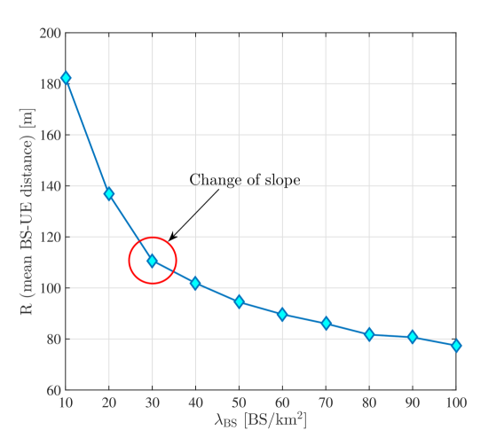
We next try to assess the number of cells that a UE can typically see. In Figure 4 we depict the mean distance of a user to its serving mmWave cell versus the SCell density in the selected area. The results show that, when the number of active SCells increases, the user can more likely find a closer cell to attach to. In this way, its propagation conditions become less demanding and the UE can reliably achieve a higher throughput. We note that a change of slope occurs when BS/km2, reflecting in a slower reduction of . In fact the initial sudden drop of , when increasing the BS density, reflects the transition from a user outage regime to a LOS/NLOS regime [2]. After that, as we persistently keep densifying the network, the SCells become so crowded that the user hardly finds a cell to build a good mmWave link with, regardless of the actual density. When this steady state is reached, the deployment of more SCells leads to a considerable increase of the system complexity, while providing a limited reduction of .
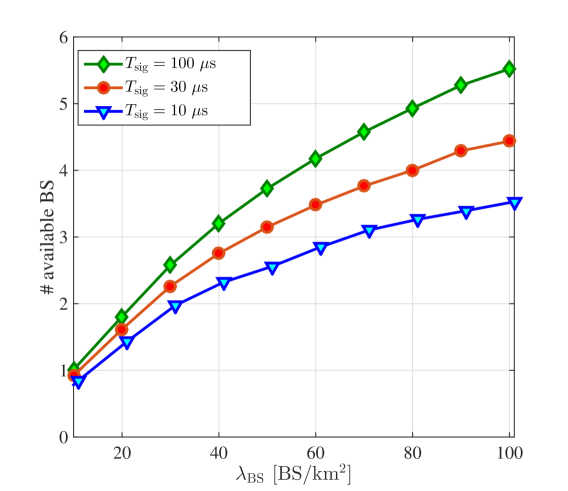
We finally show, in Figure 5, the average number of active and potentially available BSs (capable of granting SINR above threshold for the considered user) versus the SCell density , when different control signal durations are considered. We see that, when increasing the mmWave cell density, the set of cells that could possibly serve the user is increased. After Phase 2 of our proposed procedure, the macro MCell will select just one SCell for the user (according to the maximum perceived SINR). However, having at least a second active BS to which the user may connect, if its primary cell’s link is partially unavailable (e.g., due to a blockage event), can add a robustness to the network and ensure a sufficiently good QoS. From Figure 5, we see that there should be at least BS/km2, when s, in order to have, on average, at least available BSs. The number of available SCells can be increased also by increasing the signal duration: if is increased, each UE transmits its SRSs for a longer time in the same sector, so that each SCell belonging to that sector can accumulate a higher amount of energy, which results in an increased SINR. As an example, by considering s, we just need BS/km2 to have, on average, at least available SCells. This will of course increase the overall duration of the procedure, leading to latency and delay drawbacks.
V Conclusions and Future Work
A challenge for the feasibility of a 5G mmWave system is the high susceptibility to blocking that affects links in mmWave networks and results in rapid channel dynamics. In order to deal with these channel variations, a periodical directional sweep should be performed, to constantly monitor the directions of transmission of each potential link and to adapt the beam steering when a power signal drop is detected. In this work, we have proposed a novel measurement reporting system that allows a supervising centralized entity, such as the macro base station, operating in the legacy band, to periodically collect multiple reports on the overall channel propagation conditions, that can be used to make proper network decisions when implementing multiple control-plane features, such as initial access or handover. We argue that this proposed approach, which is based on uplink rather than downlink signals, can enable much more rapid and robust tracking, enabling also the use of digital beamforming architectures to dramatically reduce the measurement reporting delay.
As part of our future work, we aim at analyzing in greater detail the proposed control-plane applications that our reporting technique is suitable for, showing that keeping a record of the received signal strength variance can highly benefit the user and improve the overall network control performance. Moreover, a study on the implementation of analog, hybrid or fully digital beamforming architectures for such control-plane applications and a comparison among them deserves a deeper investigation.
References
- [1] S. Rangan, T. S. Rappaport, and E. Erkip, “Millimeter-wave cellular wireless networks: Potentials and challenges,” Proceedings of the IEEE, vol. 102, no. 3, pp. 366–385, March 2014.
- [2] M. R. Akdeniz, Y. Liu, M. K. Samimi, S. Sun, S. Rangan, T. S. Rappaport, and E. Erkip, “Millimeter wave channel modeling and cellular capacity evaluation,” IEEE Journal on Selected Areas in Communications, vol. 32, no. 6, pp. 1164–1179, June 2014.
- [3] F. B. Tesema, A. Awada, I. Viering, M. Simsek, and G. P. Fettweis, “Mobility modeling and performance evaluation of multi-connectivity in 5G intra-frequency networks,” in 2015 IEEE Globecom Workshops (GC Wkshps), Dec 2015.
- [4] J. Lu, D. Steinbach, P. Cabrol, and P. Pietraski, “Modeling the impact of human blockers in millimeter wave radio links,” ZTE Commun. Mag, vol. 10, no. 4, pp. 23–28, 2012.
- [5] M. Iwamura, K. Etemad, M. h. Fong, R. Nory, and R. Love, “Carrier aggregation framework in 3GPP LTE-advanced,” IEEE Communications Magazine, vol. 48, no. 8, pp. 60–67, August 2010.
- [6] S. Sesia, I. Toufik, and M. Baker, LTE, The UMTS Long Term Evolution: From Theory to Practice. Wiley Publishing, 2009.
- [7] H. Shokri-Ghadikolaei, C. Fischione, G. Fodor, P. Popovski, and M. Zorzi, “Millimeter wave cellular networks: A MAC layer perspective,” IEEE Transactions on Communications, vol. 63, no. 10, pp. 3437–3458, Oct 2015.
- [8] A. Talukdar, M. Cudak, and A. Ghosh, “Handoff rates for millimeterwave 5G systems,” in IEEE 79th Vehicular Technology Conference (VTC Spring), May 2014.
- [9] H. Song, X. Fang, and L. Yan, “Handover scheme for 5G C/U plane split heterogeneous network in high-speed railway,” IEEE Transactions on Vehicular Technology, vol. 63, no. 9, pp. 4633–4646, Nov 2014.
- [10] S. Sadr and R. S. Adve, “Handoff rate and coverage analysis in multi-tier heterogeneous networks,” IEEE Transactions on Wireless Communications, vol. 14, no. 5, pp. 2626–2638, May 2015.
- [11] P. Coucheney, E. Hyon, and J. M. Kelif, “Mobile association problem in heterogenous wireless networks with mobility,” in IEEE 24th Annual International Symposium on Personal, Indoor, and Mobile Radio Communications (PIMRC), Sept 2013, pp. 3129–3133.
- [12] C. N. Barati, S. A. Hosseini, S. Rangan, P. Liu, T. Korakis, S. S. Panwar, and T. S. Rappaport, “Directional cell discovery in millimeter wave cellular networks,” IEEE Transactions on Wireless Communications, vol. 14, no. 12, pp. 6664–6678, Dec 2015.
- [13] C. N. Barati, S. A. Hosseini, M. Mezzavilla, P. Amiri-Eliasi, S. Rangan, T. Korakis, S. S. Panwar, and M. Zorzi, “Directional initial access for millimeter wave cellular systems,” in 49th Asilomar Conference on Signals, Systems and Computers, Nov 2015, pp. 307–311, CoRR, vol. abs/1511.06483. [Online]. Available: http://arxiv.org/abs/1511.06483
- [14] A. Capone, I. Filippini, and V. Sciancalepore, “Context information for fast cell discovery in mm-Wave 5G networks,” in Proceedings of 21th European Wireless Conference, May 2015.
- [15] V. Desai, L. Krzymien, P. Sartori, W. Xiao, A. Soong, and A. Alkhateeb, “Initial beamforming for mmWave communications,” in 48th Asilomar Conference on Signals, Systems and Computers, Nov 2014, pp. 1926–1930.
- [16] M. Giordani, M. Mezzavilla, C. N. Barati Nt., S. Rangan, and M. Zorzi, “Comparative analysis of initial access techniques in 5G mmwave cellular networks,” in Annual Conference on Information Science and Systems (CISS), Princeton, USA, 2016.
- [17] M. Giordani, M. Mezzavilla, and M. Zorzi, “Initial access in 5G mm-Wave cellular networks,” CoRR, vol. abs/1602.07731, 2016. [Online]. Available: http://arxiv.org/abs/1602.07731
- [18] M. K. Samimi and T. S. Rappaport, “3-D statistical channel model for millimeter-wave outdoor mobile broadband communications,” in Proc. ICC, June 2015, pp. 2430–2436.
- [19] Y. Azar, G. N. Wong, K. Wang, R. Mayzus, J. K. Schulz, H. Zhao, F. Gutierrez, D. Hwang, and T. S. Rappaport, “28 GHz propagation measurements for outdoor cellular communications using steerable beam antennas in New York city,” in IEEE International Conference on Communications (ICC), June 2013, pp. 5143–5147.
- [20] T. Bai and R. W. Heath, “Coverage and rate analysis for millimeter-wave cellular networks,” IEEE Transactions on Wireless Communications, vol. 14, no. 2, pp. 1100–1114, Feb 2015.