Transverse electric surface mode in atomically thin Boron-Nitride
Abstract
The spatial confinement and the propagation length of surface waves in a single-layer two-dimensional atomic crystal are analysed in term of its surface susceptibility and its surface conductivity. Based on the values of these macroscopic parameters, extracted from experimental observations, it is confirmed that graphene supports a transverse magnetic non-radiating surface mode in the ultraviolet spectral region while a single-layer hexagonal Boron-Nitride is predicted to support a transverse electric non-radiating surface mode in the visible spectrum. This last mode, at a vacuum wavelength of 633 nm, has a spatial confinement of 15 microns and an intensity-propagation distance greater than 2 cm.
Surface electromagnetic waves have attracted lot of attention because of their fundamental interest and their possible technological impact Atwater (2007). The transverse evanescence of these modes renders them suitable for a broad range of applications because of the possibility to guide them along an interface. Recently the research in surface electromagnetic modes has been further boosted by the advent of two-dimensional (2D) atomic crystals Novoselov et al. (2005). These materials are essentially single or few atomic planes pulled out of a bulk crystal. They are stable under ambient conditions, exhibit high crystal quality, and are continuous on a macroscopic scale Novoselov et al. (2005).
In particular single-layer 2D atomic crystals have astonishing optical properties Nair et al. (2008); Mak et al. (2010). Their linear and non-linear optical response shows that they behave as zero-thickness interfaces Merano (2016a, 2015, b). In analogy to a bulk material for which it is possible to define an electrical susceptibility and a conductivity, it is possible to characterize a single-layer 2D crystal in terms of its surface electrical susceptibility and its surface conductivity. Exactly as for a 3D material these two quantities are experimentally accessible via ellipsometry Merano (2016a); Kravets et al. (2010). Optical absorption or optical contrast measurements Merano (2016a); Nair et al. (2008); Blake et al. (2007) are other experimental techniques that can be used to partially fix them.
Two-dimensional crystals can support surface electromagnetic waves. It has been predicted Vafek (2006); Wunsch et al. (2006); Hanson (2008) and experimentally shown that highly confined surface plasmons can propagate on graphene Eberlein et al. (2008); Chen et al. (2012); Fei et al. (2012). Apart from a localized transverse magnetic (TM) mode it was predicted that graphene can support also a transverse electromagnetic (TE) mode Mikhailov and Ziegler (2007). To date the existence of such a mode has only been experimentally proved in multi-layer graphene but not on a single-layer atomic crystal Menabde et al. (2016).
Owing to the 2D nature of the collective excitations it was confirmed that the confinement of surface plasmons in graphene is much stronger than that of metallic surface plasmons. This means that graphene is ideally suited to confine light down to extremely small volumes. Also because of a large wave vector mismatch of graphene plasmons compared to free-space light, plasmon excitation and detection by light is very inefficient. In spite of that marvelous experiments have successfully achieved it Chen et al. (2012); Fei et al. (2012). Real space imaging of propagating graphene plasmons has permitted the measurement of their propagation length. One of the most appealing advantages of graphene plasmonics is the possibility to electrically control the confinement and the propagation length of surface plasmons. Experiments Chen et al. (2012); Fei et al. (2012) have indeed confirmed the theoretical predictions that these quantities depend on doping Jablan et al. (2009); Wang et al. (2008); Polini et al. (2008).
Thus far strong surface plasmon damping has been observed on a graphene interface. Damping can be reduced when graphene-hexagonal-Boron-Nitride heterostructures Geim and Grigorieva (2013) are considered. Propagation lengths of hundreds of nanometers have been observed for a vacuum exciting wavelength of 10 microns Woessner et al. (2015). Even if this is still a strong sub-wavelength damping, plasmonics in these heterostructures preserves the high field confinement typical of the 2D systems.
Infrared nano-imaging has also been used to study volume confined phonon-polaritons in a flat slab of hexagonal Boron-Nitride (BN) Yoxall et al. (2015); Li et al. (2015). The measured dispersion of polaritonic waves was shown to be governed by the crystal thickness according to a scaling law that persists down to a few atomic layers Dai et al. (2014); Shi et al. (2015). A surface phonon-polariton propagating within a three layer thin flake of hexagonal BN was reported at an angular frequency around 1550 cm-1 Dai et al. (2014). Even in this case anyway a strong damping was observed.
Here I treat the surface electromagnetic modes of a single-layer 2D atomic crystal in terms of its surface conductivity and its surface electrical susceptibility. I show how the radiative or non-radiative character of these modes can be easily deduced from these quantities. Two specific examples: conducting graphene and insulating single-layer hexagonal BN will be discussed, based on the values of these macroscopic measurable parameters extracted from experimental observations. Boron-Nitride is predicted to support a TE mode with a very long propagation distance in the visible spectrum.
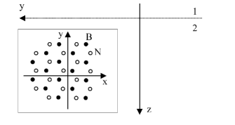
I follow an approach similar to the one used by Raether Raether (1988) for treating surface plasmon polaritons on a metallic surface. Consider a flat single-layer 2D crystal located at the interface in between two dielectric media (Fig.1), on which a TE or a TM surface electromagnetic wave propagates in the direction. In the two half-spaces () and () separated by the crystal the electric field for the TE mode is given by:
and the magnetic field for the TM mode by:
where is the angular frequency of the light and and are the components of the wave vector for the surface modes. These fields have to fulfill Maxwell’s equations and in particular the magnetic field for the TE mode is given by:
| (3) |
and the electric field for the TM mode is given by:
| (4) |
where can be or . The boundary condition for the electric field is:
| (5) |
and for the magnetic field:
| (6) |
where is the unit vector along the axis and is the sum of the surface polarization current plus the surface conduction current in the crystal plane:
| (7) |
where, because of (5), does not depend on and where is the vacuum permittivity, the electric surface susceptibility of the 2D crystal, and its surface conductivity Merano (2016a). Finally the relation:
| (8) |
must be considered, where is the magnitude of the wave vector of light in vacuum. From (Transverse electric surface mode in atomically thin Boron-Nitride), (3), (5), (6), (7) and (8) I obtain for the TE mode:
where is the impedance of vacuum and the symbol indicates that two counter-propagating directions are possible. From (Transverse electric surface mode in atomically thin Boron-Nitride), (4), (5), (6), (7) and (8) I obtain for the TM mode that is a solution of the following quartic equation:
| (10) |
where , and and are given by:
It is instructive to consider the simple case . For the TE mode I obtain:
| (12) | |||||
| (13) | |||||
| (14) |
and for the TM mode:
| (15) | |||||
| (16) | |||||
| (17) |
where and are the real and the imaginary part of a complex number, is the sign function that extracts the sign of its argument, and where the approximation sign is valid under the assumptions and .
In agreement with ref. Hanson (2008), formula (12) confirms that if the TE surface mode is not a proper solution because it is exponentially growing in the direction. If , from formulas (12) and (13) a non-radiating, spatially confined TE surface mode exists if . This has not been noted in Hanson (2008). In totally agreement with Hanson (2008) formulas (15) and (16) confirm that a non-radiating, spatially confined TM mode is possible only for .
Based on experimental values of and I show now that graphene supports a proper TM surface wave mode in the ultraviolet spectrum and a single-layer hexagonal BN supports a proper TE surface wave mode in the visible spectrum. The spatial confinement and the propagation distance of these modes are reported. The and the for graphene in the visible and ultraviolet spectral range have been determined in Merano (2016a). The and the for a single-layer hexagonal BN will be extracted here from published experimental data Gorbachev et al. (2011).
For graphene in the spectral range 450 nm 750 nm we have m and . If we consider a free-standing graphene film, from these values and formula (13) it is clear that the TE mode in the visible part of the spectrum is a radiative one (). The TM mode (formula (15)) is not spatially confined in the direction. In the same paper values of m and of at a wavelength of 270 nm are reported. In this second case the TE mode is not spatially confined in the direction. The TM mode is a proper one with a spatial confinement of the field Raether (1988) nm and an intensity propagation length Raether (1988) of nm. This mode has already been observed in ref. Eberlein et al. (2008).
I treat now the case of a single-layer hexagonal BN. From ref. Gorbachev et al. (2011) that reports optical contrast measurements of BN on top of a wafer with a thickness of 290 nm, and the analysis used in ref. Merano (2016a) it is possible to extract the value of m and an upper limit for . Figure 2 reports the experimental data published in Fig (2) of ref. Gorbachev et al. (2011) that have been extracted from the original paper via software digitization. The observed contrast is a non-monotonic function of and changes its sign at 530 nm. From simulations it emerges that the optical contrast for BN is sensitive to the sign of . If the sign of is reversed the sign of the contrast is reversed. The maximum and the minimum values of the contrast increase with the magnitude of . Increasing shifts the curve upwards. This is the reason why for graphene the contrast is either positive or negligible Blake et al. (2007). The spectral position for which the contrast changes sign depends a lot on the substrate and not on or . The two fits reported in fig. 2 are for the same best values of and . One is for the nominal thickness of 290 nm reported in Gorbachev et al. (2011) and the best one for a thickness of 270 nm . No other experimental data have been found in literature to better fix and .

Even if I choose the upper possible value for , from formulas (12) and (13) a free-standing, single-layer BN supports a non-radiative TE surface mode in the visible part of the spectrum. The spatial confinement of the field for a wavelength of 633 nm is 15 m, (a weakly localized mode) and the intensity propagation length is 2 cm, a surprising macroscopic distance. For a smaller conductivity, that it is not possible to exclude here, this propagation distance will be proportionally longer (formula 14). This mode exists not only for a free-standing crystal but also if a single-layer BN is embedded in a dielectric (formulas Transverse electric surface mode in atomically thin Boron-Nitride). The TM surface mode is not spatially confined in the direction.
The validity of the equations here reported is not limited to graphene or single-layer BN. They can be applied to any single-layer 2D crystal, for instance transition-metal dichalcogenides. By elucidating the role of and in the properties of surface electromagnetic waves in 2D materials, this paper may profit to the experimental research in this field.
Based on experimental values of and , I have shown that graphene supports a non radiating TM surface mode in the ultraviolet spectral region while a single-layer hexagonal BN supports a non-radiative TE surface mode in the visible spectrum. The two modes have very different properties. The TM mode has a very high spatial confinement and an exceedingly short propagation distance. The TE mode has a weak spatial confinement and a long propagation distance.
While TM surface waves in graphene have been observed both in the ultraviolet Eberlein et al. (2008) and in the infrared electromagnetic spectrum Chen et al. (2012); Fei et al. (2012), a TE surface mode has never been observed on any single-layer two-dimensional atomic crystal Mason et al. (2014); Degli-Eredi et al. (2015). Boron-Nitride can be a good candidate for its observation in the visible spectrum. When compared with the TM mode in graphene, this TE mode has a giant propagation length. This makes it interesting both from a fundamental point of view as well as for technical applications.
References
- Atwater (2007) H. Atwater, Sci. Am. 296, 56 (2007).
- Novoselov et al. (2005) K. Novoselov, D. Jiang, F. Schedin, T. Booth, V. Khotkevich, S. Morozov, and A. Geim, PNAS 102, 10451 (2005).
- Nair et al. (2008) R. R. Nair, P. Blake, A. N. Grigorenko, K. S. Novoselov, T. J. Booth, T. Stauber, N. M. R. Peres, and A. K. Geim, Science 320, 1308 (2008).
- Mak et al. (2010) K. F. Mak, C. Lee, J. Hone, J. Shan, and T. F. Heinz, Phys. Rev. Lett. 105, 136805 (2010).
- Merano (2016a) M. Merano, Phys. Rev. A 93, 013832 (2016a).
- Merano (2015) M. Merano, Opt. Express 23, 31602 (2015).
- Merano (2016b) M. Merano, Opt. Lett. 41, 187 (2016b).
- Kravets et al. (2010) V. G. Kravets, A. N. Grigorenko, R. R. Nair, P. Blake, S. Anissimova, K. S. Novoselov, and A. K. Geim, Phys. Rev. B 81, 155413 (2010).
- Blake et al. (2007) P. Blake, E. W. Hill, A. H. Castro Neto, K. S. Novoselov, D. Jiang, R. Yang, T. J. Booth, and A. K. Geim, Appl. Phys. Lett. 91, 063124 (2007).
- Vafek (2006) O. Vafek, Phys. Rev. Lett. 97, 266406 (2006).
- Wunsch et al. (2006) B. Wunsch, T. Stauber, F. Sols, and F. Guinea, New J. Phys. 8, 318 (2006).
- Hanson (2008) G. W. Hanson, J. Appl. Phys. 103, 064302 (2008).
- Eberlein et al. (2008) T. Eberlein, U. Bangert, R. Nair, R. Jones, M. Gass, A. Bleloch, K. Novoselov, A. Geim, and P. Briddon, Phys. Rev. B 77, 233406 (2008).
- Chen et al. (2012) J. Chen, M. Badioli, P. Alonso-Gonzlez, S. Thongrattanasiri, F. Huth, J. Osmond, M. Spasenovi, A. Centeno, A. Pesquera, P. Godignon, A. Zurutuza Elorza, N. Camara, F. Javier Garca De Abajo, R. Hillenbrand, and F. Koppens, Nature 486, 77 (2012).
- Fei et al. (2012) Z. Fei, A. Rodin, G. Andreev, W. Bao, A. McLeod, M. Wagner, L. Zhang, Z. Zhao, M. Thiemens, G. Dominguez, M. Fogler, A. Castro Neto, C. Lau, F. Keilmann, and D. Basov, Nature 486, 82 (2012).
- Mikhailov and Ziegler (2007) S. A. Mikhailov and K. Ziegler, Phys. Rev. Lett. 99, 016803 (2007).
- Menabde et al. (2016) S. Menabde, D. Mason, E. Kornev, C. Lee, and N. Park, Sci. Rep. 6, 21523 (2016).
- Jablan et al. (2009) M. Jablan, H. Buljan, and M. Soljačić, Phys. Rev. B 80, 245435 (2009).
- Wang et al. (2008) F. Wang, Y. Zhang, C. Tian, C. Girit, A. Zettl, M. Crommie, and Y. Shen, Science 320, 206 (2008).
- Polini et al. (2008) M. Polini, R. Asgari, G. Borghi, Y. Barlas, T. Pereg-Barnea, and A. H. MacDonald, Phys. Rev. B 77, 081411 (2008).
- Geim and Grigorieva (2013) A. K. Geim and I. V. Grigorieva, Nature 499, 419 (2013).
- Woessner et al. (2015) A. Woessner, M. Lundeberg, Y. Gao, A. Principi, P. Alonso-Gonzlez, M. Carrega, K. Watanabe, T. Taniguchi, G. Vignale, M. Polini, J. Hone, R. Hillenbrand, and F. Koppens, Nat. Mat. 14, 421 (2015).
- Yoxall et al. (2015) E. Yoxall, M. Schnell, A. Nikitin, O. Txoperena, A. Woessner, M. Lundeberg, F. Casanova, L. Hueso, F. Koppens, and R. Hillenbrand, Nat. Photonics 9, 674 (2015).
- Li et al. (2015) P. Li, M. Lewin, A. Kretinin, J. Caldwell, K. Novoselov, T. Taniguchi, K. Watanabe, F. Gaussmann, and T. Taubner, Nat. Commun. 6, 7507 (2015).
- Dai et al. (2014) S. Dai, Z. Fei, Q. Ma, A. Rodin, M. Wagner, A. McLeod, M. Liu, W. Gannett, W. Regan, K. Watanabe, T. Taniguchi, M. Thiemens, G. Dominguez, A. Castro Neto, A. Zettl, F. Keilmann, P. Jarillo-Herrero, M. Fogler, and D. Basov, Science 343, 1125 (2014).
- Shi et al. (2015) Z. Shi, H. Bechtel, S. Berweger, Y. Sun, B. Zeng, C. Jin, H. Chang, M. Martin, M. Raschke, and F. Wang, ACS Photonics 2, 790 (2015).
- Raether (1988) H. Raether, Surface Plasmons on Smooth and Rough Surfaces and on Gratings, 1st ed. (Springer-Verlag, 1988) pp. 4–6 and 118–119.
- Gorbachev et al. (2011) R. V. Gorbachev, I. Riaz, R. R. Nair, R. Jalil, L. Britnell, B. D. Belle, E. W. Hill, K. S. Novoselov, K. Watanabe, T. Taniguchi, A. K. Geim, and P. Blake, Small 7, 465 (2011).
- Mason et al. (2014) D. R. Mason, S. G. Menabde, and N. Park, Opt. Express 22, 847 (2014).
- Degli-Eredi et al. (2015) I. Degli-Eredi, J. E. Sipe, and N. Vermeulen, Opt. Lett. 40, 2076 (2015).