Long-Range Dipole-Dipole Interaction and Anomalous Förster Energy Transfer across Hyperbolic Meta Material
Abstract
We study radiative energy transfer between a donor-acceptor pair across a hyperbolic metamaterial slab. We show that similar to a perfect lens a hyperbolic lens allows for giant energy transfer rates. For a realistic realization of a hyperbolic multilayer metamaterial we find an enhancement of up to three orders of magnitude with respect to the transfer rates across a plasmonic silver film of the same size especially for frequencies which coincide with the epsilon-near zero and the epsilon-near pole frequencies. Furthermore, we compare exact results based on the S-matrix method with results obtained from effective medium theory. Our finding of very large dipole-dipole interaction at distances of the order of a wavelength has important consequences for producing radiative heat transfer, quantum entanglement etc.
pacs:
78.70.−g,78.20Ci,42.50.−pI Introduction
Dipole-dipole interactions are at the heart of many fundamental interactions such as van der Waals forces and vacuum friction MilonniBook ; Volokitin2007 , Förster (radiative) energy transfer (FRET) Forster ; DungEtAl2002 , radiative heat transfer Volokitin2007 ; BiehsAgarwal2013b , quantum information protocols like the realization of CNOT gates Nielsen ; Bouchoule2002 ; Isenhower2010 , pairwise excitation of atoms VaradaGSA1992 ; HaakhEtAl2015 ; HettichEtAl2002 , and Rydberg blockade SaffmanEtAl ; GilletEtAl . Clearly large number of problems in physics and chemistry require very significant dipole-dipole interaction at distances which are not much smaller than a wavelength. The development of plasmonic and metamaterial platforms can considerably enhance these fundamental dipole-dipole interactions. In an early work GSASub it was shown that the dipole-dipole interaction GSASub ; ElGanainy2013 can be quite significant even at distances bigger than microns if one utilizes whispering gallery modes of a sphere. More recently such systems have been revisited for their remarkable quantum features like squeezing HaakhEtAl2015 . Further it was shown that the energy transfer across plasmonic metal films can be enhanced AndrewBarnes2004 and that the long range plasmons allow for long-range plasmon assisted energy transfer between atoms placed on plasmonic structures such as graphene Velizhanin2012 ; AgarwalBiehs2013 ; KaranikolasEtAl2016 and metals BiehsAgarwal2013 ; Poudel2015 ; LiEtAl2015 ; CanoEtAl2010 ; BouchetEtAl2016 .
More elaborate structures possessing more features than simple single-layer plasmonic structures are for ex- ample hyperbolic metamaterials (HMM) HuChui2002 ; Smith2003 , which exhibit a broadband enhanced LDOS SmolyaninovNarimanov2010 allowing for broadband enhanced spontaneous emission ZubinEtAl2012 ; PoddubnyEtAl2011 ; ChebykinEtAl2012 ; KidwaiEtAl2012 ; IorshEtAl2012 ; PotemkinEtAl2012 ; KidwaiEtAl2011 ; OrlovEtAl2011 ; KimEtAl2012 ; KrishnamorthyEtAl2012 ; GalfskyEtAl2015 ; WangEtAl2015 , hy- perbolic lensing JacobEtAl2006 ; FengAndElson2006 ; CegliaEtAl2014 , negative refraction SmithEtAl2004 ; HoffmanEtAl2007 and broadband enhanced thermal emission Nefedov2011 ; Biehs2012 ; GuoEtAl2012 ; Biehs2 ; ShiEtAl2015 ; Biehs2015 , for instance. These HMM can be artificially fabricated by a periodic layout of sub-wavelength metal and dielectric components but they also exist in nature ThompsonEtAl1998 ; CaldwellEtAl2014 ; EsslingerEtAl2014 ; NarimanovKildishev2015 ; KorzebEtAl2015 . Here we concentrate on artificially fabricated HMM since the choice of fabrication parameters makes it possible to control the epsilon-near zero (ENZ) and the epsilon-near pole (ENP) frequencies. At these frequencies the HMM can show extra-ordinary features as enhanced superradiance Fleury2013 and supercoupling Silvereinha2006 ; EdwardsEtAl2008 .
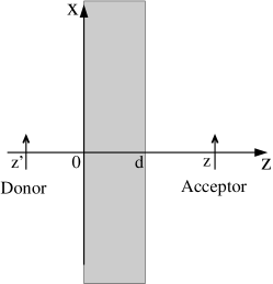
The aim of our work is to study FRET across a hyperbolic multilayer metamaterial (see Fig. 1). We will demonstrate that similar to the perfect lens effect Pendry2000 , the dipole-dipole interaction across a HMM can be enhanced by orders of magnitude compared to the pure plasmonic enhancement by a thin plasmonic metal layer.
The organization of our paper is as follows: In Sec. II we introduce the elementary relations for FRET between a donor and an acceptor which are separated by an intermediate slab. We discuss the possibility of a perfect dipole-dipole interaction which is studied in Sec. III analytically and numerically for a thin silver film. Then, in Sec. IV, we discuss the anomalous transmission across a hyperbolic metamaterial as an alternative for realizing perfect dipole-dipole interaction. Finally, in Sec. V we study FRET across a concrete hyperbolic structure using exact S-matrix calculations. The exact numerical results are compared with the approximative results of effective medium theory.
II Possibility of Perfect Dipole-Dipole Interaction
The Förster energy transfer rate between an donor-acceptor pair as sketched in Fig. 1 is well-known and can be written in terms of the dyadic Green’s function as DungEtAl2002
| (1) |
where and are the absorption and emission spectra of the acceptor and donor and
| (2) |
introducing the dipole-transition matrix elements and of the donor and acceptor.
Making a plane wave expansion of the dyadic Green’s function, we obtain
| (3) |
where , , and
| (4) |
introducing the vacuum wavevector in z-direction and the vacuum wavenumber . Note that the expression for the Green’s function contains the contribution of the propagating () and evanescent () waves. The evanescent wavas are exponentially decaying in z-direction so that during propagation these contributions are lost unless the medium somehow can reverse the decay of such waves. Here and are the transmission coefficients of the s- and p polarization and are the polarization vectors defined by
| (5) |
The transmission coefficients for a metamaterial film can be expressed as Pendry2000 ; HuChui2002
| (6) | ||||
| (7) |
where the wavevector component inside the medium in z-direction is given by . Note that the dipole-dipole interaction in free space (i.e. if we replace the film by vacuum) can be obtained from the Green’s tensor in Eq. (4) by setting the transmission coefficients to one (which is the result for ), i.e.
| (8) |
In this case the dipole-dipole interaction would become infinitely large if the donor and the acceptor would be placed at the same position, that means if . From a mathematical point of view this is so because the exponential prefactor equals one for so that the -integral in Eq. (3) would diverge due to the fact that an infinite number of evanescent waves with would contribute to the energy transfer. On the other hand, it is well known that the dipole-dipole interaction between the donor and acceptor is proportional to which diverges for , since we here have and as shown in the Fig. 1.
For an ideal left-handed material exhibiting negative refraction the permittivity and permeability are given by . In such a material evanescent plane waves are amplified as shown by Pendry when he introduced the concept of a perfect lens Pendry2000 . For the here defined transmission coefficients we obtain for
| (9) |
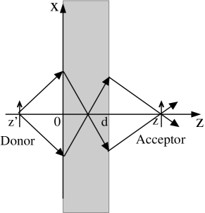
showing clearly the feature of amplification of evanscent waves inside the ideal left-handed material. Note, that this exponential amplification stems from the exponential in the denominator of the transmission coefficients. This is just the same expression derived by Pendry showing that for the perfect lens both propagating and evanescent waves contribute to the resolution of the image Pendry2000 which leads to the perfect lensing effect depicted in Fig. 2.
Inserting the expression of the transmission coefficients in the Green’s tensor describing the dipole-dipole interaction gives
| (10) |
This Green’s tensor is the same as expression (8) of the vacuum Green’s tensor with the important difference that now the argument of the exponential prefactor is different. As in the case of interaction in free space we have an infinite large energy transfer if the exponential equals one leading to the condition that . Hence by placing the donor-acceptor pair such that this condition is fullfilled corresponds to a dipole-dipole interaction for two dipoles at the same position leading to an infinitely large energy transfer rate. This is so, because for all evanescent waves () get focused. We have thus shown that a pefect negative material with zero losses can yield perfect dipole-dipole interaction and perfect energy transfer which is limited only by the donor and acceptor line shapes.
III Silver Film as Metamaterial
As pointed out by Pendry Pendry2000 for observing the perfect lensing effect it suffices to consider a thin silver film. In the quasistatic-limit such a thin silver film mimicks a perfect lens for the p-polarized waves at a frequency where , which coincides with the surface plasmon resonance frequency of a single metal interface. To see this we take the quasi-static limit () of the transmission coefficient in Eq. (7) with . We obtain
| (11) |
The exponential in the numerator vanishes because in the quasi-static limit . If we now insert
| (12) |
then we arrive at
| (13) |
It is now easy to see that for vanishing losses we again have ()
| (14) |
Proving that a silver film can mimick a perfect lens. The only drawback is that in metals the losses are not negligible so that the perfect lens effect does not persist in this case. Nonetheless even with losses one can expect to find large Förster energy transfer due to the fact that the donor and acceptor can couple to the surface waves inside the silver film.
That the coupling to the surface plasmons can enhance the energy transfer has been demonstrated theoretically for different systems like nanoparticles GerstenNitzan1984 , plasmonic waveguides CanoEtAl2010 and films BiehsAgarwal2013 ; Poudel2015 as well as graphene Velizhanin2012 ; AgarwalBiehs2013 ; KaranikolasEtAl2016 . This enhanced energy transfer might be exploited for solar energy conversion LiEtAl2015 . Experimentally it has been shown by Viger et al. VigerEtAl2011 and Zhang et al. ZhangEtAl2014 that plasmonic nanoparticles can enhance the energy transfer rate; Andrew and Barnes AndrewBarnes2004 have proven experimentally that the Förster energy transfer across thin silver films can be enhanced by the coupling to the surface plasmon polaritons demonstrating a long-range coupling between the donor-acceptor pair across films with thicknesses up to 120nm. Although we are here particularly interested in the long-range energy transfer across a film, surface plasmons can also be used to mediate the energy transfer along plasmonic structures as shown theoretically CanoEtAl2010 ; BiehsAgarwal2013 ; Poudel2015 ; Velizhanin2012 ; AgarwalBiehs2013 ; KaranikolasEtAl2016 . Recently, Bouchet et al. BouchetEtAl2016 have detected this long-range energy transfer when both donor and acceptor are placed on a plasmonic platform like a thin metal film.
To see how the Förster energy transfer is affected by the presence of a metal film, we consider therefore first a thin silver layer with permittivity described by the Drude model
| (15) |
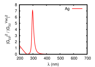
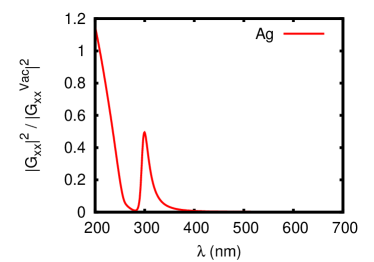
with the paramters , , . In order to quantify the enhancement of the energy transfer we introduce the enhancement factor
| (16) |
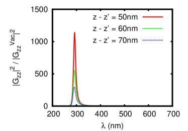
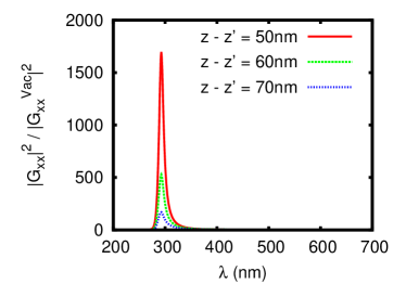
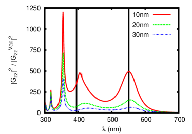
where is the orientation of the dipole-transition matrix element of the donor/acceptor and is the vacuum Green’s function. In Fig. 3 we show our results for the enhancement of the dipole-dipole interaction due to the presence of a silver film of thickness with respect to the case where this film is replaced by vacuum. It can be seen that the dipole-dipole interaction and therefore the Förster energy transfer is especially large for where as expected. Furthermore it can be seen that at no particular effect happens. The Förster energy transfer becomes just less important when the distance between the donor-acceptor pair is increased. In Fig. 4 we show similar results for a much thicker film with . In this case there can be still seen an enhancement effect for orientation but of course the enhancement effect becomes less important when the thickness of the silver film is increased due the losses inside the metal film. Therefore another kind of material is needed in order to overcome the harmful effect of the losses. Nonetheless such an enhancement due to the surface plasmons of the silver film have already been measured in the experiment by Andrew and Barnes AndrewBarnes2004 for film thicknesses of and even .
IV Anomalous Transmission for Hyperbolic Materials
Now, let us replace the ideal left-handed material slab by a hyperbolic or indefinite material Smith2003 . The beauty of such hyperbolic materials is that waves with large kappa () emitted by a donor which would be evanescent in free space are homogenous within these materials. This leads to significant fields on the other side of the slab which makes hyperbolic materials very advantageous for energy transfer even for slabs with an appreciable thickness. Hyperbolic materials are uni-axial materials which do exist in nature ThompsonEtAl1998 ; CaldwellEtAl2014 ; EsslingerEtAl2014 ; NarimanovKildishev2015 ; KorzebEtAl2015 . But they can also be easily fabricated by combining alternating layers of dielectric and plasmonic materials in a periodic structure, for instance. Here, we consider only the non-magnetic case so that the permeability tensor is given by the unit tensor and the permittivity tensor is given by with respect to the principal axis. In our case the z-axis is the optical axis of the uni-axial material. The dispersion relations of the ordinary and extra-ordinary modes inside the uni-axial medium are YehBook
| (17) |
where () is the z-component of the wavevector of the ordinary (extraordinary) mode. Neglecting dissipation for a moment we can easily define normal dielectric uni-axial materials as materials with and and hyperbolic materials as materials with , i.e. one of both permittivites is positiv and the other one negative. Due to the property and the iso-frequency curves for dielectric uni-axial materials in k-space are ellipsoids whereas for hyperbolic materials these iso-frequency curves are hyperboloids. For and — a type I hyperbolic material — the iso-frequency curve is a two-sheeted hyperboloid and for and — a type II hyperbolic material — the iso-freqency curve is a one-sheeted hyperboloid. In Fig. 5 the iso-frequency lines of a type I hyperbolic material are sketched in the - plane.
Now we will show that similar to the perfect lensing effect the evanescent waves can be amplified inside a hyperbolic slab even in the absence of a magnetic response. To this end, we consider the transmission coefficients of a uniaxial slab where the optical axis is normal to the interface, i.e. it is along the z-axis. In this case the transmission coefficients for the ordinary and extraordinary modes (which coincide with the s- and p-polarized modes) are given by
| (18) | ||||
| (19) |
The effect of anisotropy is mainly seen in the transmission coefficient because only here both permittivities and enter. When considering an epsilon-near-zero (ENZ) material with , then so that the exponential in the denominator of and is one and we find
| (20) |
That means that similar to the perfect lensing effect, the evanescent waves are amplified by uni-axial material and in particular by a hyperbolic structure. Note, that this time the exponential which enhances the evanescent modes stems from the numerator of the transmission coefficient which makes this effect more robust against losses. Similarly, when considering an epsilon-near-pole (ENP) material with , then remains unaffected because remains unaltered. But for the extra-ordinary wave we have . It follows that
| (21) |
with
| (22) |
Therefore and the evanescent modes are again amplified, if the -dependent prefactor is not too small.
To summarize, we find that for ENZ and ENP frequencies evanescent waves in vacuum are amplified and the dipole-dipole interaction can at least in principle become infinitely large if , i.e. if the donor and the acceptor are both exactly deposited on the surface of the hyperbolic film which cannot be achieved in a real setup. But even if this condition is not perfectly met, we can expect to find an amplified energy transfer across a hyperbolic slab at the ENZ and ENP frequencies. Furthermore, from the above derivation suggests that the ENZ resonance is more advantageous for transmission than the ENP resonance, because the prefactor fullfills for typically .
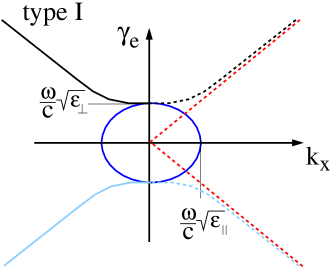
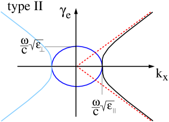
Note, that both regimes of ENZ and ENP were discussed in the context of diffraction suppressed hyperbolic lensing FengAndElson2006 , using the canalization regime for hyperbolic lensing BelovEtAl2005 ; BelovHao2006 and directed dipole emission CegliaEtAl2014 . In these cases, the advantage of using ENZ and ENP resonances lies in the resulting very flat iso-frequency line of the extraordinary modes so that the group velocity is mainly directed along the optical axis for a very broad band of lateral wavenumbers . This becomes clear when looking at the asymptotes of the isofrequency lines of as shown in Fig. 5. For large wavenumbers (evanescent regime) we have . With this result we can evaluate the ratio of the group velocity along the z-axis and the group velocity perpendicular to the z-axis and obtain
| (23) |
Hence, at the ENZ and ENP resonance the slope of the isofrequency lines become infinitely small and the group velocity becomes mainly directed parallel to the optical axis so that the energy transferred between the donor and acceptor flows preferentially along the line connecting both, if both are placed along the optical axis.
V S-Matrix Calculation of the Dipole-Dipole Interaction
Let us turn to a concrete numerical example. We consider a hyperbolic multilayer metamaterial made of alternating layers of silver and TiO2 which has for example been used in the experiment in Ref. KrishnamorthyEtAl2012 . In most treatments of such multilayer materials, effective medium theory (EMT) is used which describes the multilayer structure as a homogenous but uni-axial material, with an optical axis perpendicular to the interfaces. Within EMT the effective permittivities of the multilayer structure can be easily calculated and are given by
| (24) | ||||
| (25) |
where is the filling fraction of silver and / are the permittivites of the both constitutents of the multilayer structure. For silver we use the Drude model in Eq. (15). TiO2 is transparent in the visible regime. It’s permittivity is nearly constant in that regime and can be well described by the formula Devore1951
| (26) |
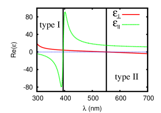
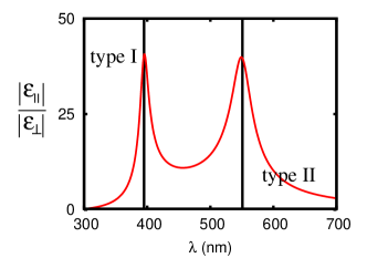
where is the wavelength in micrometer. The effective permittivties and are shown in Fig. 6 for a filling fraction of . It can be seen that at the edges of the hyperbolic bands we find the ENP and ENZ points at and . To make these points more obvious we show in Fig. 6 a plot of . By changing the filling fraction the position of the ENZ and ENP frequencies can be shifted. When increasing the filling fraction the dielectric band in between both hyperbolic bands in Fig. 6 will become smaller until , then the frequencies of ENP and ENZ coinside since in this case both hyperbolic bands (type I and type II) are in juxtaposition with each other.
However, the EMT is only applicable if the considered wavelengths and distances are much larger than the period of the multilayer structure KidwaiEtAl2012 ; IorshEtAl2012 ; IorshEtAl2012 ; OrlovEtAl2011 ; TschikinEtAl2013 . Furthermore, EMT cannot account for the ordering of the layers so that it can be very important if we consider a finite Ag/TiO2 or TiO2/Ag multilayer material TschikinEtAl2013 . Therefore we will use mainly full S-matrix calculations AuslenderHava1996 to determine the transmission coefficients of the multilayer hyperbolic film. Here, we choose silver as first layer which is facing the donor. Hence, the last layer facing the acceptor is made of TiO2.
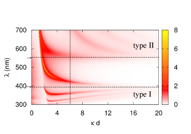
The transmission coefficient of the extra-ordinary waves is plotted in Fig. 7 for a Ag/TiO2 multilayer structure of thickness with a filling fraction of of silver. The calculation was made for layers, which means that the silver layers have a thickness of 3.5nm and the TiO2 layers have a thickness of 6.5nm which is at the lower limit of a realizable structure. In Fig. 7 the different coupled surface modes of the hyperbolic multilayer structure can be seen. Obviously in the type I hyperbolic band the coupled surface modes can exhibit negative group velocities which will result in negative refraction HoffmanEtAl2007 . Furthermore it can be niceley seen that all the coupled modes converge for large towards the ENZ and ENP frequencies (vertical lines). Therefore at those ENZ and ENP frequencies we have quite a number of surface modes with zero group velocity in direction of the interfaces of the multilayer structure. These are the waves which will contribute dominantly to the Förster energy transfer having a group velocity rather along the optical axis (z-direction) than perpendicular to it as shown in Eq. (23). This is so, because for the evanescent waves with large the exponentials in the Green’s function in Eq. (4) introduce a cutoff 111For the numeric integration we use a cutoff at which is much larger than the intrinsic cutoff of the integrand at . at at the ENP and ENZ frequencies for the -integral, since in this case. Therefore the major conributions stem from around . That means in the ideal case all evanescent waves contribute, but in the non-ideal realistic case only evanescent waves up to a finite value of will contribute to the energy transfer.
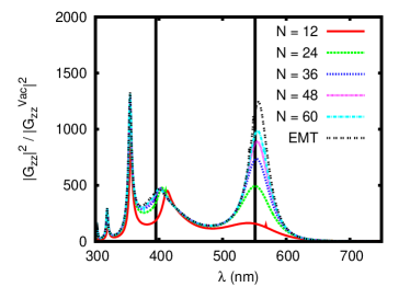
In Fig. 8 we show now the results for the enhancement factors and of the Förster energy transfer by a Ag/TiO2 hyperbolic multilayer structure. It can be seen that the enhancement is especially large close to the ENZ and ENP frequencies. Furthermore, the enhancement is more than two orders of magnitude larger than for a single silver film in Fig. 4, so that this enhancement of energy transfer due to the ENP and ENZ resonances is much larger than the enhancement due to the thin film surface plasmons. Since the latter has already been measured by Andrew and Barnes AndrewBarnes2004 the ENP and ENZ enhancement should be easily measurable. Note, that by increasing the number of layer in the multilayer film or by increasing the distance of the donor-acceptor pair with respect to the film the exact S-matrix result converges to the EMT result.
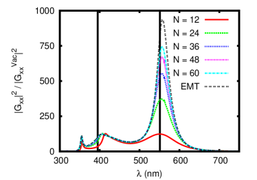
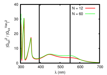
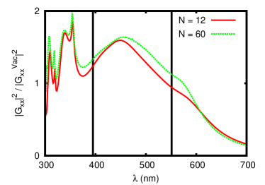
The position of the peaks can be explained be the fact that the dominant contributions to the energy transfer stem from in this case. The vertical line in Fig. 7 is exactly at this value. It can be seen that the frequencies at which the coupled surface modes cross this vertical line coincide with the resonances of the energy transmission in Fig. 8. If we would increase the donor-acceptor distance the vertical line would move to smaller values in Fig. 7 so that the resonances will shift accordingly. This shifting of the resonances is shown in Fig. 9. Obviously, the enhancement around the ENZ and ENP frequencies gets smaller and smaller, when the distance of the donor and acceptor with respect to the surface is increased. However as can be seen in Fig. 10, there can still be an enhancement of 30 for the energy transfer inside the type I hyperbolic band if the distance of the donor and acceptor with respect to the surface of the hyperbolic medium has relative large values as for example so that .
VI Conclusion
In conclusion, we have discussed the perfect lens effect and its pendant for hyperbolic metamaterials in the context of Förster energy transfer between a donor-acceptor pair placed on each side of the perfect or hyperbolic lens. We have demonstrated that in principle in both cases one can have an infinitely large dipole-dipole interaction for precisely defined positions of the donor-acceptor pair and well-defined frequencies which coincide with the surface plasmon frequency in the case of a perfect lens and the epsilon-near zero or epsilon-near infinity frequency for the hyperbolic lens. Due to losses this interactions becomes finite but it remains large compared to the dipole-dipole interaction in vacuum. The main reason for such large enhancements is that the enhancment effect in HMM is much more robust against the negative influence of losses, whereas the perfect lens effect is quite susceptible to losses. Finally, we have studied the effect numerically using an exact S-matrix method and realistic material parameters for a Ag/TiO2 mulilayer HMM. The numerical results show that FRET can be enhanced by two to three orders of magnitude by using a HMM instead of a thin silver film of same thickness. Since the plasmonic enhancement of FRET for a thin silver film has already been observed, a measurement of the enhancment due to the hyperbolic material should be feasible. Such a realization is important not only for FRET but for other areas like production of quantum entanglement AgarwalBook .
References
- [1] P. W. Milonni, The Quantum Vacuum, (Academic Press, 1994).
- [2] A. I. Volokitin and B. N. J. Persson, Rev. Mod. Phys. 79, 1291 (2007).
- [3] T. Förster, Ann. Phys. 2, 55 (1948).
- [4] H. T. Dung, L. Knöll, and D.-G. Welsch, Phys. Rev. A 65, 043813 (2002).
- [5] S.-A. Biehs and G. S. Agarwal, J. Opt. Soc. Am. B 30, 700 (2013).
- [6] M. A. Nielsen and I. L. Chuang, Quantum Computation and Quantum Information, (Cambridge University Press, Cambridge,2000).
- [7] I. Bouchoule and K. Molmer, Phys. Rev. A 65, 041803 (2002).
- [8] L. Isenhower, E. Urban, X. L. Zhang, A. T. Gill, T. Henage, T. A. Johnson, T. G. Walker, and M. Saffman, Phys. Rev. Lett. 104, 010503 (2010).
- [9] G. V. Varada and G. S. Agarwal, Phys. Rev. A 45, 6721 (1992).
- [10] H. R. Haakh and D. Martin-Cano, ACS Photonics 2, 1686 (2015).
- [11] C. Hettich, C. Schmitt, J. Zitzmann, S. Kühn, I. Gerhardt and V. Sandoghdar, Science 298, 385 (2002).
- [12] M. Saffman, T. G. Walker, T. G. and K. Molmer, Rev. Mod. Phys. 82, 2313 (2010).
- [13] J. Gillet, G. S. Agarwal and T. Bastin, Phys. Rev. A 81, 013837 (2010).
- [14] G. S. Agarwal and S. Dutta Gupta, arXiv:quant-ph/0011098.
- [15] R. El-Ganainy, S. John, New J. Phys. 15, 083033 (2013).
- [16] P. Andrew and W. L. Barnes, Science 306, 1002 (2004).
- [17] K. A. Velizhanin and T. V. Shahbazayan, Phys. Rev. B 86, 245432 (2012).
- [18] G. S. Agarwal and S.-A. Biehs, Opt. Lett. 38, 4421 (2013).
- [19] V. D. Karanikolas, C. A. Marocico, and A. L. Bradley, Phys. Rev. B 93, 035426 (2016).
- [20] S.-A. Biehs and G. S. Agarwal, Appl. Phys. Lett. 103, 243112 (2013).
- [21] A. Poudel, X. Chen, and M. A. Ratner, arxic:1601.04338v1 (2015).
- [22] J. Li, S. K. Cushing, F. Meng, T. R. Senty, A. D. Bristow, and N. Wu, Nat. Phot. 9, 601 (2015).
- [23] D. Martin-Cano, L. Martın-Moreno, F.J. Garcıa-Vidal, and E. Moreno, Nano Lett. 10, 3129(2010).
- [24] D. Bouchet, D. Cao, R. Carminati, Y. De Wilde, and V. Krachmalnicoff, Phys. Rev. Lett. 116, 037401 (2016).
- [25] L. Hu and S. T. Chui, Phys. Rev. B 66, 085108 (2002).
- [26] D. R. Smith and D. Schurig, Phys. Rev. Lett. 90, 077405 (2003).
- [27] I. I. Smolyaninov and E. E. Narimanov, Phys. Rev. Lett. 105, 067402 (2010).
- [28] Z. Jacob, I. Smolyaninov, and E. Narimanov, Appl. Phys. Lett. 100, 181105 (2012).
- [29] A. N. Poddubny, P. A. Belov, and Y. S. Kivshar, Phys. Rev. A 84, 023807 (2011).
- [30] A. V. Chebykin, A. A. Orlov, and P. A. Belov, Opt. Spectr. 109, 938 (2010).
- [31] A. S. Potemkin, A. N. Poddubny, P. A. Belov, and Y. S. Kivshar, Phys. Rev. A 86, 023848 (2012).
- [32] O. Kidwai, S. V. Zhukovsky, and J. E. Sipe, Phys. Rev. A 85, 053842 (2012).
- [33] I. Iorsh, A. N. Poddubny, A. A. Orlov, P. A. Belov, and Y. S. Kivshar, Phys. Lett. A 376, 185 (2012)
- [34] O. Kidwai, S. V. Zhukovsky, and J. E. Sipe, Opt. Lett. 36, 2530 (2011).
- [35] A. A. Orlov, P. M. Voroshilov, P. A. Belov, and Y. S. Kivshar, Phys. Rev. B 84, 045424 (2011).
- [36] J. Kim V. P. Drachev, Z. Jacob, G. V. Naik, A. Boltasseva, E. E. Narimanov, and V. M. Shalaev, Opt. Exp. 20, 8100 (2012).
- [37] H. N. S. Krishnamoorthy, Z. Jacob, E. E. Narimanov, I. Kretzschmar, and V. M. Menon, Science 336, 205 (2012).
- [38] T. Galfsky, H. N. S. Krishnamoorthy, W. Newman, E. E. Narimanov, Z. Jacob, and V. M. Menon, Optica 2, 62 (2015).
- [39] Y. Wang, H. Sugimoto, S. Inampudi, A. Capretti, M. Fuji, and L. Dal Negro, Appl. Phys. Lett. 106, 241105 (2015).
- [40] Z. Jacob, L. V. Alekseyev, E. Narimanov, Opt. Exp. 14, 8247 (2006).
- [41] S. Feng and J. M. Elson, Opt. Exp. 14, 216 (2006).
- [42] D. de Ceglia, M. A. Vincenti, S. Campione, F. Capolino, J. W. Haus, and M. Scalora, Phys. Rev. B 89, 075123 (2014).
- [43] D. R. Smith, P. Kolinko, and D. Schurig, J. Opt. Soc. Am. B 21, 1032 (2004).
- [44] A. J. Hoffman, L. Alekseyev, S. S. Howard, K. J. Franz, D. Wasserman, V. A. Podolskiy, E. E. Narimanov, S. L. Sivco, and C. Gmachl, Nature Mat. 6, 946 (2007).
- [45] I. S. Nefedov and C. R. Simovski, Phys. Rev. B 84, 195459 (2011).
- [46] S.-A. Biehs, M. Tschikin, P. Ben-Abdallah, Phys. Rev. Lett. 109, 104301 (2012).
- [47] Y. Guo, C. L. Cortes, S. Molesky, and Z. Jacob, Appl. Phys. Lett. 101, 131106 (2012).
- [48] S.-A. Biehs, M. Tschikin, R. Messina, and P. Ben-Abdallah, Appl. Phys. Lett. 102 131106 (2013).
- [49] J. Shi, B. Liu, P. Li, L. Y. Ng, and S. Shen, Nano Letters 15, 1217 (2015).
- [50] S.-A. Biehs, S. Lang, A. Yu. Petrov, M. Eich, and P. Ben-Abdallah, Phys. Rev. Lett. 115, 174301 (2015).
- [51] D. W. Thompson, M. J. DeVries, T. E. Tiwald, and J. A. Woollam, Thin Solid Films 313-314, 341 (1998).
- [52] J. D. Caldwell, A. Kretinin, Y. Chen, V. Giannini, M. M. Fogler, Y. Francescato, C. T. Ellis, J. G. Tischler, C. R. Woods, A. J. Giles, M. Hong, K. Watanabe, T. Taniguchi, S. A. Maier, K. S. Novoselov, arXiv:1404.0494.
- [53] M. Esslinger, R. Vogelgesang, N. Talebi, W. Khunsin, P. Gehring, S. de Zuani, B. Gompf, and K. Kern, ACS Photonics, 1, 1285(2014).
- [54] E. E. Narimanov and A. V. Kildishev, Nature Photonics 9. 214 (2015).
- [55] K. Korzeb, M. Gajc, and D. A. Pawlak, Opt. Expr. 23, 25406 (2015).
- [56] R. Fleury and A. Alú, Phys. Rev. B 87, 201101(R) (2013).
- [57] M. Silveirinha and N. Engheta, Phys. Rev. Lett. 97, 157403 (2006).
- [58] B. Edwards, A. Alú, M. E. Young, M. Silveirinha, and N. Engheta, Phys. Rev. Lett. 100, 033903 (2008).
- [59] J. B. Pendry, Phys. Rev. Lett. 85, 3966 (2000).
- [60] J. I. Gersten and A. Nitzan, Chem. Phys. Lett. 104, 31 (1984).
- [61] M. L. Viger, D. Brouard, and D. Boudreau, J. Phys. Chem. C 115, 2974 (2011).
- [62] X. Zhang, C. A. Marocico, M. Lunz, V. A. Gerard, Y. K. Gunko, V. Lesnyak, N. Gaponik, A. S. Susha,A. L. Rogach, and A. L. Bradley†, ACS Nano 8, 1273 (2014).
- [63] P. Yeh, Optical Waves in Layered Media, (John Wiley & Sons, New Jersey, 2005).
- [64] P. A. Belov, C. R. Simovski, and P. Ikonen, Phys. Rev. B 71, 193105 (2005).
- [65] P. A. Belov and Y. Hao, Phys. Rev. B 73, 113110 (2006).
- [66] M. Tschikin, S.-A. Biehs, R. Messina, P. Ben-Abdallah, J. Opt. 15, 105101 (2013).
- [67] M. Auslender and S. Have, Opt. Lett. 21, 1765 (1996).
- [68] J. R. Devore, J. Opt. Soc. Am. 41, 416 (1951).
- [69] See Sec. 15.3 of G. S. Agarwal, Quantum Optics, (Cambridge University Press, Cambridge, 2012).