Path-polarization hyperentangled and cluster states of photons on a chip
Running Title: Hyperentangled photon states on a chip
Abstract
Encoding many qubits in different degrees of freedom (DOFs) of single photons is one of the routes towards enlarging the Hilbert space spanned by a photonic quantum state. Hyperentangled photon states (i.e. states showing entanglement in multiple DOFs) have demonstrated significant implications for both fundamental physics tests and quantum communication and computation. Increasing the number of qubits of photonic experiments requires miniaturization and integration of the basic elements and functions to guarantee the set-up stability. This motivates the development of technologies allowing the precise control of different photonic DOFs on a chip. We demonstrate the contextual use of path and polarization qubits propagating within an integrated quantum circuit. We tested the properties of four-qubit linear cluster states built on both DOFs and we exploited them to perform the Grover’s search algorithm according to the one-way quantum computation model. Our results pave the way towards the full integration on a chip of hybrid multiqubit multiphoton states.
I Introduction
Novel integrated photonic circuits built on a single chip have been recently introduced within the realm of quantum information Politi08 , disclosing new perspectives towards quantum communication Barreiro08 , quantum computation Politi09 , and the quantum simulation of physical phenomena Feynman82 ; Lloyd96 ; Crespi13 ; Spring13 ; Tillmann13 ; Broome13 . The next generation of integrated quantum circuits (IQCs), incorporating highly efficient photon sources Kruse15 ; Herrmann13 ; Silverstone14 ; Silverstone15 and detectors Goltsman01 ; Gaggero10 ; Sprengers11 ; Pernice12 ; Sahin13 , are expected to have a large impact in future photonic quantum technologies and are essential to achieve a level of complexity and stability of the operations higher than what previously demonstrated. The miniaturization of integrated photonic devices represents a necessary step towards the implementation of state-of-the art quantum information protocols, which require an exponentially high number of elements and an increasing stability, impossibile to achieve with standard bulk optical setup. Inherently stable interferometer networks, composed of waveguides, beam splitters and phase shifters, built in two dimensions on different material platforms, such as silicon, silicon nitride and others, are realized by lithography, a well established technique already developed for telecom wavelengths. This approach allows the fabrication of a large number of replicas of the same circuit by using a single mask and represents at the moment the strongest candidate for a large-scale production of IQCs. While it has been demonstrated that the operation complexity performed by such systems may be very high, it is worth to remember that they are still limited by the need of using a large number of photons. Moreover, only path-encoded qubits are allowed in such systems, since polarization qubits are degraded by the intrinsic large birefringence of the material substrate or of the waveguide itself. On the other hand, several applications in the quantum domain, such as quantum computation and quantum communications, may greatly benefit from the possibility of manipulating and controlling polarization qubits.
Femtosecond laser writing, recently introduced for IQC applications Marshall09 ; Sansoni10 ; Heilmann2014 , allows to write in three dimensions circular transverse waveguide profiles able to support the propagation of nearly Gaussian modes with any polarization state, while keeping highly stable the phase of path-encoded qubits. Besides, this technique makes it possible to perform arbitrary transformations of the polarization state by suitable integrated devices, such as polarization beam splitters Crespi11 and waveguide-based optical waveplates Heilmann2014 ; Corrielli14 .
Nowadays, the building blocks necessary to perform the basic operations with path- and polarization-qubits are available. Time is right to demonstrate the simultaneous control of two different degrees of freedom of the photons within the same chip. In this work we manipulate path- and polarization-encoded qubits belonging to a 2-photon 4-qubit hyperentangled/cluster state Barbieri05 ; Cinelli05 ; Barreiro05 ; Vallone07 ; Chen07 and propagating through an integrated quantum circuit. This enabled us to demonstrate the Grover’s algorithm on a four element database, in a one-way quantum computing approach.
II Materials and Methods
Our experimental setup is depicted in Fig. 1 and Fig. 2 and consists of a hyperentangled-photon source, a manipulation stage, which includes the integrated photonic chip, and a detection stage. The source generates pairs of photons, hyperentangled in the path and polarization DOFs, via spontaneous-parametric down conversion at 710 nm by a BBO type I nonlinear crystal Barbieri05 . Polarization entanglement is produced by optical superposition of two cones of perpendicular polarization created by double passage, back and forth, of a UV laser pump through the BBO crystal from both sides Cinelli04 . Path entanglement is generated by selecting with a 4-hole screen two pairs of correlated spatial modes, namely , and , .
The generated hyperentangled (HE) state is:
| (1) |
where and label the two photons; , , , and identify the four spatial modes, while and represent the two possible polarization states for each photon. As will be discussed in the following, the phases and , corresponding respectively to the polarization and path DOFs, can be independently controlled.
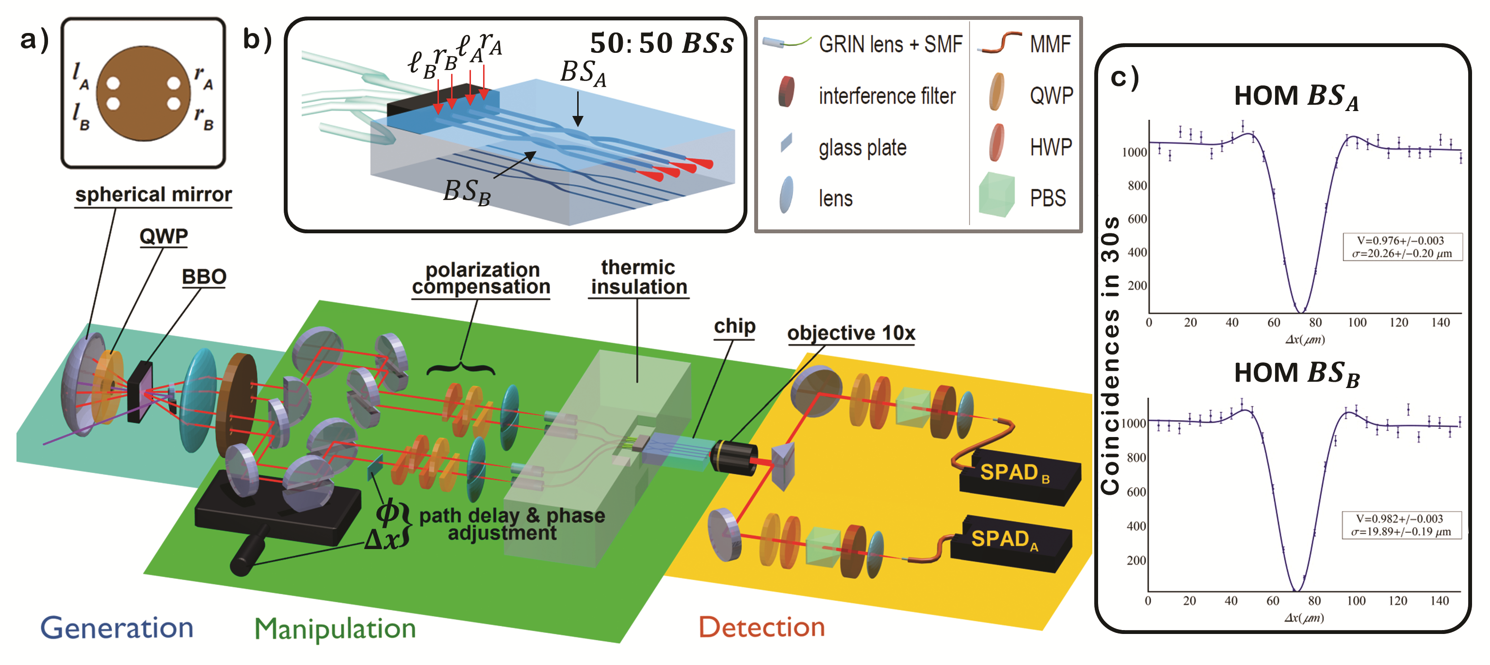
The chip consists of two waveguide balanced beam splitters ( and ), yielding polarization insensitive behaviourSansoni12 , fabricated by femtosecond laser waveguide writingDellaValle09 using the second harmonic (=515 nm) of a Yb:KYW cavity-dumped laser oscillator (300 fs pulse duration, 1 MHz repetition rate). Femtosecond laser pulses are focused by a 0.6 NA microscope objective into the volume of the glass substrate (EAGLE 2000, Corning), where nonlinear energy absorption creates a permanent and localized refractive index increase. Waveguides are produced by smoothly translating the sample under the laser beam, using Aerotech FiberGLIDE 3D air-bearing stages. Under proper irradiation conditions (100 nJ pulse energy and 10 mm s-1 translation speed) single-mode waveguides at 710 nm are produced, at 170 depth below the glass surface, characterized by a mode diameter of 8 m, propagation loss of 1.5 dB cm-1 and coupling loss to single mode fibers 1 dB per facet. Integrated beam splitters are realized following a particular three-dimensional directional-coupler designSansoni12 that ensures insensitivity to the polarization. To achieve a balanced splitting ratio the waveguides, initially 127 m far, are brought closer (with a bending radius of 90 mm) down to 10 distance for an interaction length of 1.8 mm. Overall chip length is 34 mm.
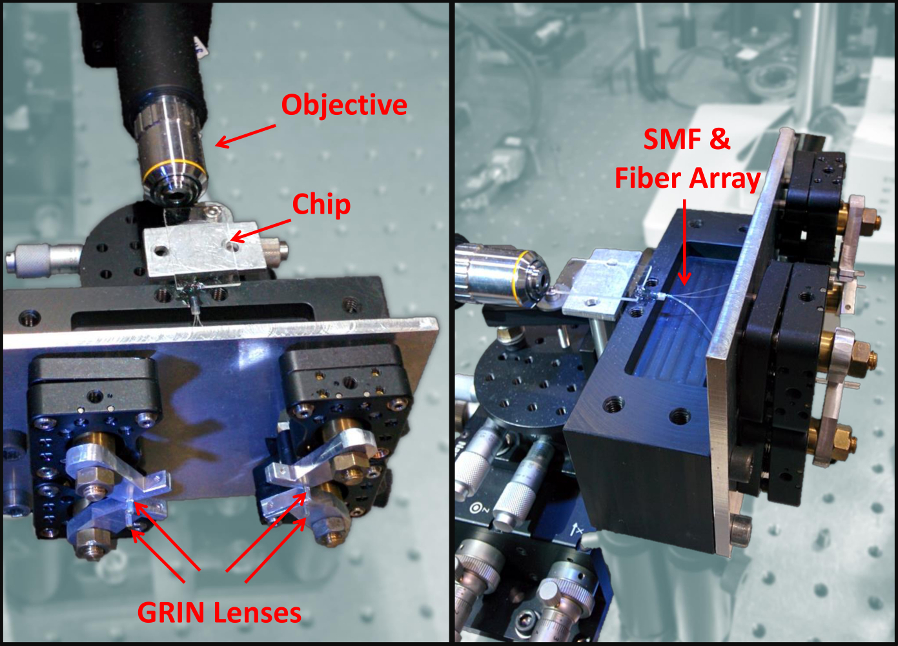
The four modes , and , are coupled to the input ports of and , respectively, through a 8 cm long, single mode fiber array, terminated at the input side by a set of four Gradient Index (GRIN) lenses. One of the main technical issue is given by the independent injection of each mode into the corresponding GRIN lens; this is performed by using for each mode a set of custom made half-mirrors and one half-lens. Besides, polarization compensation is individually performed for each mode through a properly chosen set of half waveplates (HWPs) and quarter waveplates (QWPs). Finally, the fiber array is thermally insulated from the environment in order to guarantee path stability. Output light from the chip is collected by a 10 objective. The coupling ratios of the 4 modes in each optical component and the overall transmission efficiency are provided in the Supplementary Information. Two interference filters centred at 710 nm select 10 nm bandwidth and ensure photon indistinguishability, and two avalanche photodiode (APD) detectors measure coincidences between output modes , that are coupled to the detectors through multi mode fibers (we label , and , the output modes of and respectively).
Figure 1c shows the Hong-Ou-Mandel (HOM) dips obtained when the two photons are injected within and , respectively. We obtained the following visibilities: for and for , thus showing the correct operation of the two systems. After removing accidental coincidences every 30 sec, we obtain and .
III Results and Discussion
In a first experiment, we injected in the chip the path-polarization HE state:
| (2) |
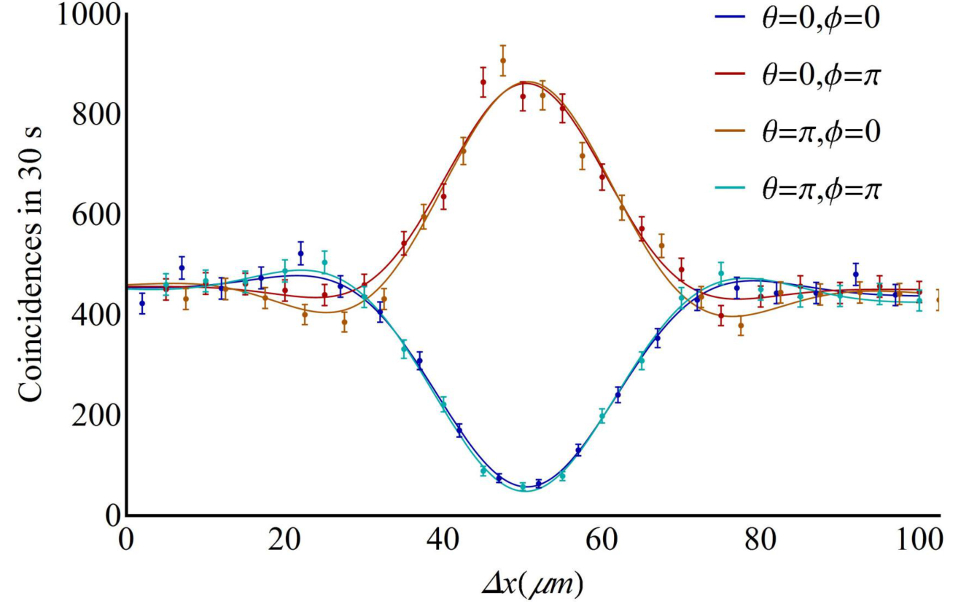
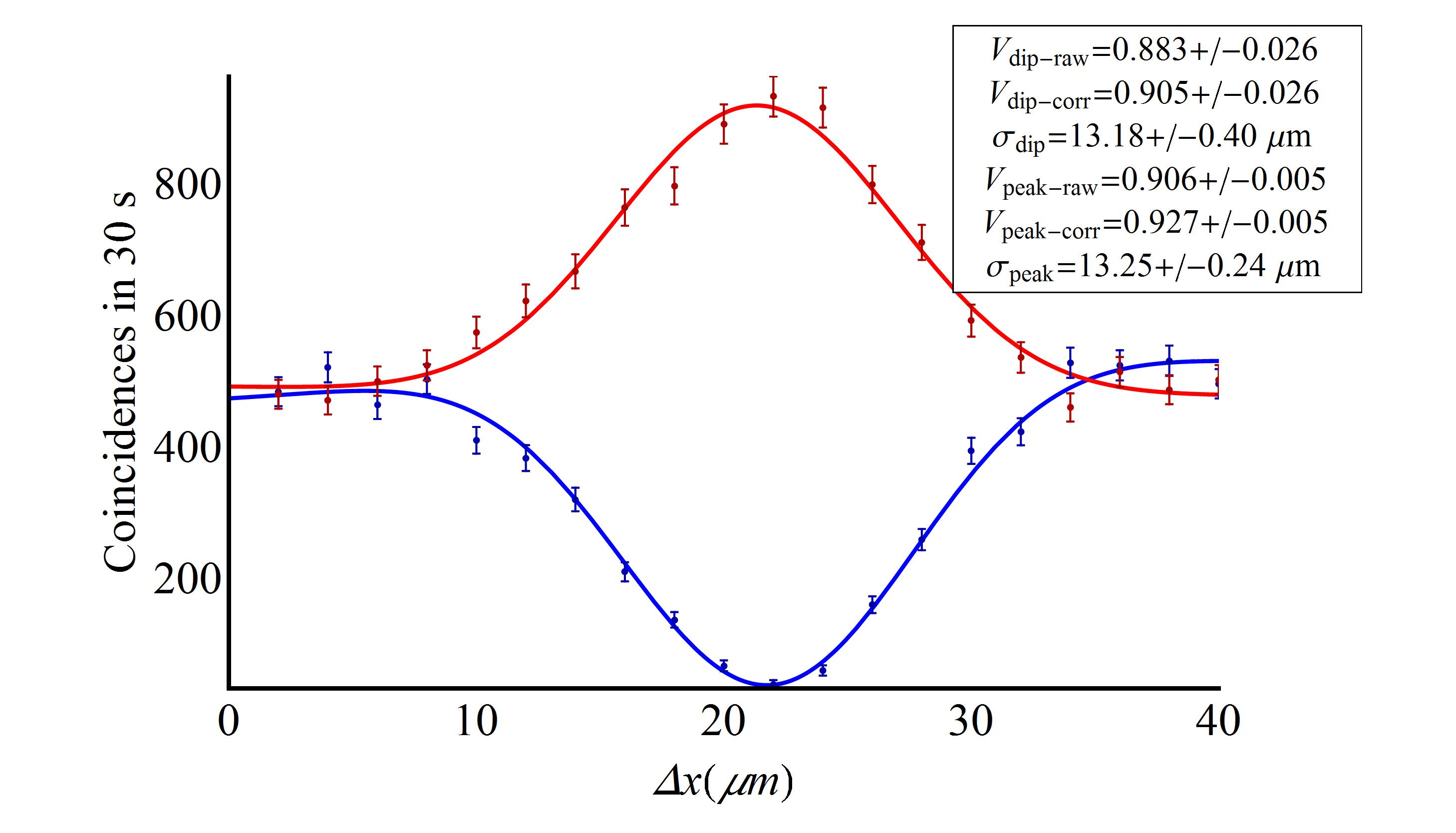
where and . This state was obtained from Eq. (1) by introducing the polarization transformation using the compensation waveplates shown in Fig. 1 such that and on modes and while and on and . In this way, we were able to guarantee the polarization compensation over the entire system, which includes the fiber array and the chip, on the computational polarization basis. In order to compensate the two pairs of correlated modes on the diagonal basis, we introduced before the compensation plates on mode an additional half HWP at zero degrees. As the addition of the plate preserves the compensation in the computational basis, we tilted it along its vertical axis in order to keep constant the phase difference between the two couples of modes. This ensures the simultaneous compensation on the polarization degree of freedom. Arbitrary values for the parameters and in Eq. (1) can be set by translating the spherical mirror within the HE source and by tilting an additional glass plate on mode , respectively. The plus signs appearing in Eq. (2) were achieved by setting and the minus signs are obtained by setting . The overall symmetry of the state determines the behaviour of the two photons: if the wavefunction of the HE state is symmetric they emerge from the same output port of the beam-splitters, corresponding to a coincidence dip, while the expected result in the case of an antisymmetric wavefunction is a coincidence peak. This behaviour can be analysed by recovering the dips and peaks of path entanglement varying both and so that a dip can be obtained with and a peak with .Results are shown in Fig. 3. The average peak/dip visibilities are and . These results are comparable with those of Ref. Barbieri05 and prove the achievement of path-polarization hyperentanglement on chip with good fidelity.
In a second experiment, the same hyperentangled source was used to engineer a four-qubit cluster state encoded in the path and polarization DOFs of the two photons:
where . At variance with standard hyperentangled states, four qubits cluster states are not biseparable and present genuine multipartite entanglement Briegel01 . They can be thought as graphs where the vertices are the physical qubits initially in the state , and each edge represents a controlled-phase gate entangling the two connected nodes. As an example, in this graphical representation a HE state is equivalent, up to single qubit transformations, to the graph formed by two disjointed couples of vertices, as shown in Fig. 4a. A cluster state can then be obtained by connecting these pairs of qubits. In our case this was easily performed by inserting a zero-order HWP in mode oriented along the optical axis, as explained later. In the One-Way Quantum Computation model Raussendorf01 , cluster states provide the entire resource for the computation as the information is written, processed and read out by single-qubit measurements on the physical qubits of the cluster. This approach to quantum computation transfers the main complexity of the process from the ability to implement multi-qubit gates to the capability to create the initial cluster state. It is therefore well-suited for quantum optical schemes where states can be produced with high fidelity while photon-photon interactions are difficult to achieve, thus precluding two-qubits gates from linear optical circuits.
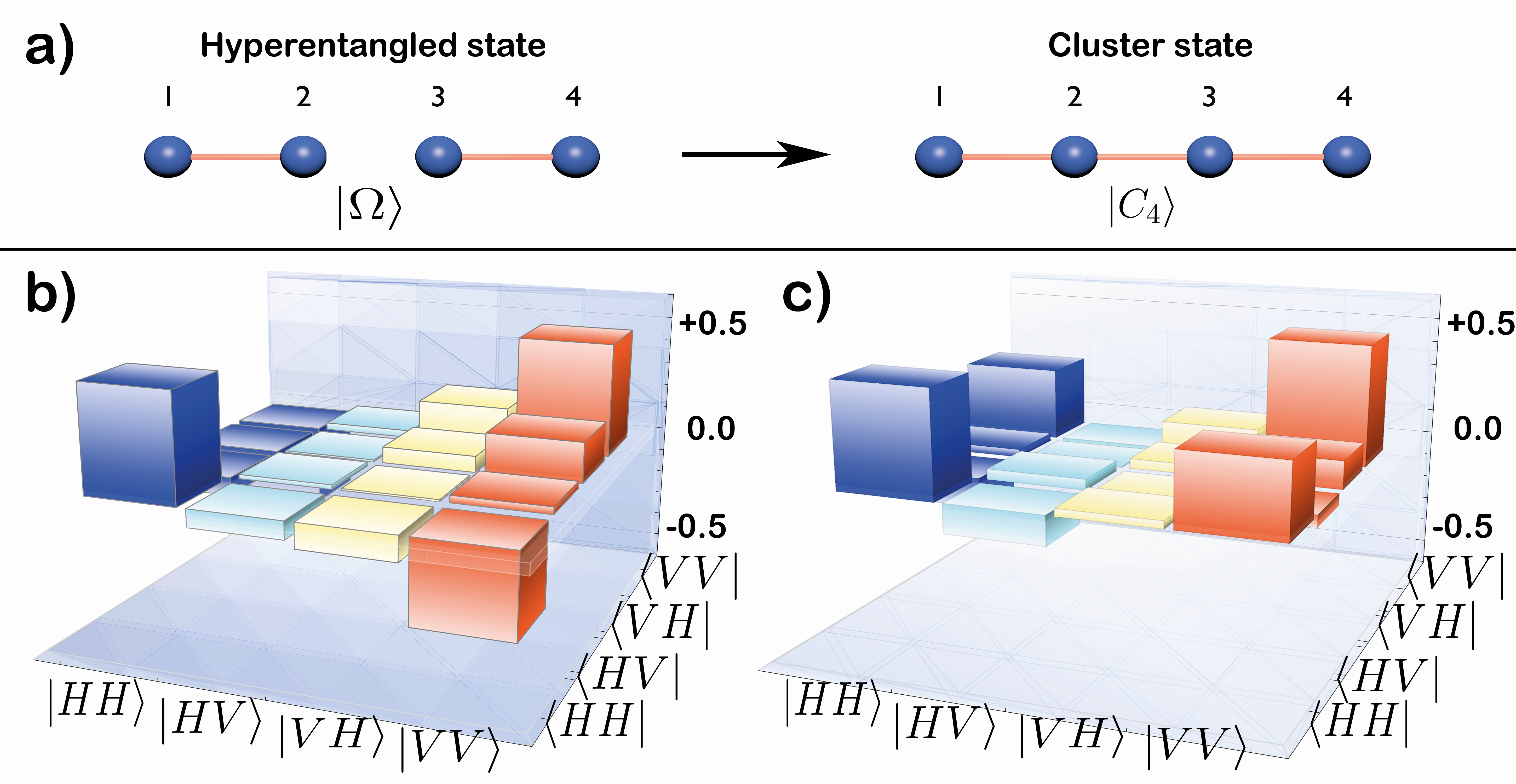
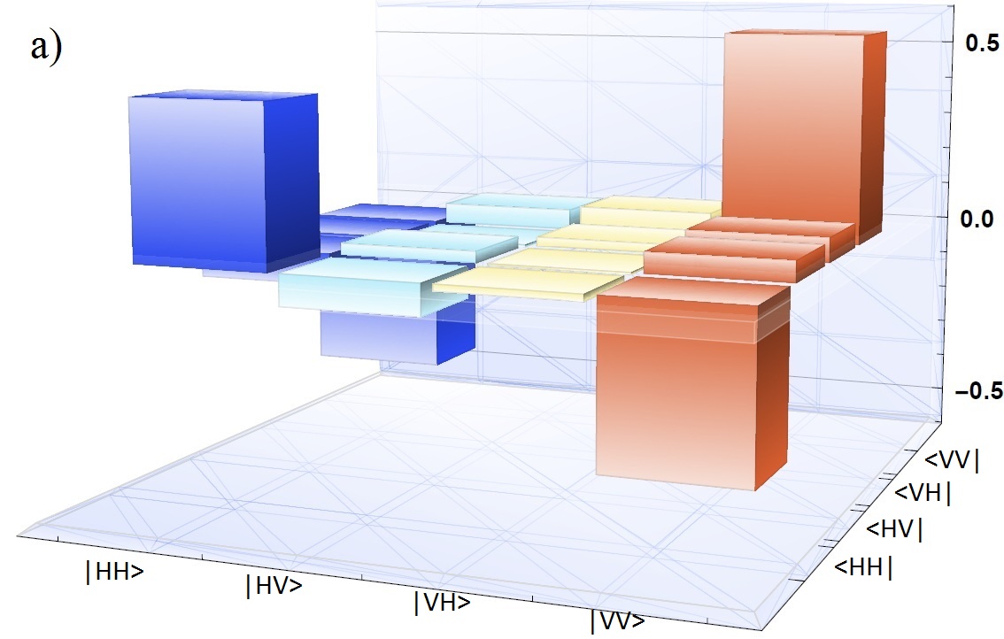
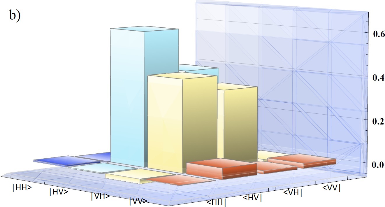
Starting from the HE state and inserting a zero order, zero degrees HWP in mode we were able to change the polarization of from to while keeping unchanged, thus creating the cluster state . The quantum state tomographies corresponding to the two mode pairs are reported in Fig. 4b-c and correspond to the following parameters:
Here is the fidelity and is the concurrence of the experimental state, while errors are calculated from a Monte Carlo analysis of the experimental data. The obtained results are comparable with those of the tomographies of the hyperentanglement source reported in the SI, thus proving that the cluster state is correctly generated. The stabilizer formalism, explained in Ref. Toth05 can be adopted to measure a genuine multipartite entanglement witness:
| (3) |
where upper case , define the Pauli operators for the polarization of the state, lower case , define the Pauli operators for the momentum. The state is entangled when and particularly it is purely entangled for . The polarization dependent stabilizers are measured by rotating the analysis waveplates (Fig. 1). The two beamsplitters perform the transformation in the path of each photon and , where is achieved by changing the phase , i.e. tilting the correspondent glass plate on mode . This manipulation allows us to measure the momentum-dependent stabilizers involving . We report in Tab. 1 the measured outcomes for the stabilizers. The overall value of demonstrates that the state presents genuine multipartite entanglement, and we can derive a lower boundToth05 for the fidelity of the created cluster state . This result is comparable with that of Ref. Vallone07 .
| +0.940 0.028 | |
|---|---|
| -0.860 0.030 | |
| +0.860 0.030 | |
| -0.990 0.007 | |
| +0.8092 0.036 | |
| +0.8081 0.035 |
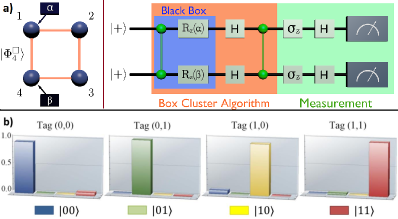
Finally, the quality of the created cluster state was tested by performing the Grover’s search algorithm for a four element database. This is, to the best of our knowledge, the first achievement of a one-way quantum computation basic operation based on multiple DOFs through integrated photonics. The quantum circuit is represented in Fig. 5a. It consists of two qubits initially prepared in the state , a black box tagging one item of the database and an operation which allows us to identify the tagged item in the readout. The algorithm can be implementedRaussendorf01 ; Browne05 using the four qubit box cluster state defined in Refs. Walther05 ; Vallone08A . An approach based on a linear optic implementation of the Grover’s algorithm using multiple DOFs was originally proposed by Kwiat et al.Kwiat00 . Following Fig. 5a, the black box tags the item by choosing the bases and for the measurements on qubits 1 and 4. The information is processed and read on qubits 2 and 3. Labelling the physical qubits in the order , with standing for the path (polarization) qubits, the cluster state is equivalent to up to the single qubit unitaries
| (4) |
can be implemented by simply rotating the measurement basis, as is a single qubit transformation. First, we performed a probabilistic computation where we post-selected the cases with no errors occurring in the one-way computation modelVallone08A ; Vallone08B . The results are reported in Fig. 5b in which we show that the average success rate in identifying the correct item in the database is at an average protocol rate of 17 Hz. This result is probabilistic and depends on the postselection of the measurement outcomes. We may then apply a feed-forward protocol in which the outcomes are relabelled depending on the results of the measurements performed by the black box Walther05 ; Vallone08A . In this case the computation is deterministic with a success rate of and protocol rate of 68 Hz. This procedure of passive feed-forward corresponds to corrections made in the post-selection process by relabelling the outputs.
IV Conclusions
In this work four-qubit hyperentangled states built on the path and polarization of two photons have been adopted to manipulate qubits based on the two degrees of freedom and propagating through an integrated photonic circuit fabricated by the femtosecond laser writing technique. The device was used to test the presence of path and polarization entanglement. We also engineered cluster states and we measured a multipartite genuine entanglement witness to estimate the purity of correlations within the entangled state. For both experiments we achieved fidelities comparable with previous bulk experiments Barbieri05 ; Vallone07 , thus showing the good quality of the experimental results. We exploited the cluster state to perform Grover’s search algorithm as an experimental realization on a chip of the one-way quantum computation on chip using different DOFs. Our experiment provides the first demonstration that it is possible to use simultaneously different degrees of freedom of the photons within an integrated photonic circuit, thus increasing the number of qubits. A future step forward in this approach will include the use of more complex circuits for the active manipulation of both phase and polarization inside the same device.
Note added: During the review process of this work, the experimental realization of an integrated CNOT gate for measurement-based on-chip quantum computation has been reported Carolan15 .
Acknowledgments
This work was supported by the European Union through the project FP7-ICT-2011-9-600838 (QWAD Quantum Waveguides Application and Development; www.qwad-project.eu) and by FIRB, Futuro in Ricerca HYTEQ.
References
- (1) Politi, A, Cryan, MJ, Rarity, JG, Yu, S, and O’Brien, JL. Science 320(5876), 646-649 (2008).
- (2) Barreiro, JT, Wei, TC, and Kwiat, PG. Nature Phys. 4(4), 282-286 (2008).
- (3) Politi, A, Matthews, JCF., and O’Brien, JL. Science 325(5945), 1221 (2009).
- (4) Feynman, RP. Int. J. Theor. Phys. 21, 467-488 (1982).
- (5) Lloyd, S. Science 273(5278), 1073-1078 (1996).
- (6) Crespi, A, Osellame, R, Ramponi, R, Brod, DJ, Galvo, EF, Spagnolo, N et al. Nature Photon. 7, 545-549 (2013).
- (7) Spring, JB, Metcalf, BJ, Humphreys, PC, Kolthammer, WS, Jin, XM, Barbieri, M, et al. Science 339(6121), 798-801 (2013).
- (8) Tillmann, M, Dakić, B, Heilmann, R, Nolte, S, Szameit, A, and Walther, P. Nature Photon. 7, 540-544 (2013).
- (9) Broome, MA, Fedrizzi, A, Rahimi-Keshari, S, Dove, J, Aaronson, S, Ralph, TC et al. Science 339(6121), 794-798 (2013).
- (10) Bentivegna, M, Spagnolo, N, Vitelli, C, Flamini, F, Viggianiello, N et al. Sci. Adv.1, e1400255 (2015).
- (11) Kruse, R, Sansoni, L, Brauner, S, Ricken, R, Hamilton, CS, Jex, I et al. Phys. Rev. A 92 , 053841 (2015).
- (12) Herrmann, H, Yang, X, Thomas, A, Poppe, A, Sohler, W, and Silberhorn, C. Opt. Express 21, 27981-27991 Nov (2013).
- (13) Silverstone, JW, Bonneau, D, Ohira, K, Suzuki, N, Yoshida, H, Iizuka et al. Nature Photon. 8, 104-108 (2014).
- (14) Silverstone, JW, Santagati, R, Bonneau, D, Strain, MJ, Sorel, M. et al. Nature Comm. 6, 7948 (2015).
- (15) Goltsman, GN, Okunev, O, Chulkova, G, Lipatov, A, Semenov, A, Smirnov et al. Appl. Phys. Lett. 79(6), 705-707 (2001).
- (16) Gaggero, A, Nejad, SJ, Marsili, F, Mattioli, F, Leoni, R, Bitauld, D, et al. Appl. Phys. Lett. 97, 151108 (2010).
- (17) Sprengers, JP, Gaggero, A, Sahin, D, Jahanmirinejad, S, Frucci, G, Mattioli, F et al. Appl. Phys. Lett. 99, 181110 (2011).
- (18) Pernice, W, Schuck, C, Minaeva, O, Li, M, Goltsman, G, Sergienko, A et al. Nat. Commun. 3, 1325 (2012).
- (19) Sahin, D, Gaggero, A, Zhou, Z, Jahanmirinejad, S, Mattioli, F, Leoni, R et al. Appl. Phys. Lett. 103, 111116 (2013).
- (20) Marshall, GD, Politi, A, Matthews, JCF, Dekker, P, Ams, M, Withford, MJ. et al. Opt. Express 17(15), 12546-12554 Jul (2009).
- (21) Sansoni, L, Sciarrino, F, Vallone, G, Mataloni, P, Crespi, A, Ramponi, R et al. Phys. Rev. Lett. 105, 200503 Nov (2010).
- (22) Heilmann, R, Gräfe, M, Nolte, S, and Szameit, A. Sci. Rep. 4, 04118, Feb (2014).
- (23) Crespi, A, Ramponi, R, Osellame, R, Sansoni, L, Bongioanni, I, Sciarrino, F, Vallone, G et al. Nat. Commun. 2, 566 (2011).
- (24) Corrielli, G, Crespi, A, Geremia, R, Ramponi, R, Sansoni, L, Santinelli, A et al. Nat. Commun. 5, 4249 (2014).
- (25) Barbieri, M, Cinelli, C, Mataloni, P, and De Martini, F. Phys. Rev. A 72, 052110 Nov (2005).
- (26) Cinelli, C, Barbieri, M, Perris, R, Mataloni, P, and Martini, FD. Phys. Rev. Lett. 95, 240405 Dec (2005).
- (27) Barreiro, JT, Langford, NK, Peters, NA, and Kwiat, PG. Phys. Rev. Lett. 95, 260501 Dec (2005).
- (28) Vallone, G, Pomarico, E, Mataloni, P, De Martini, F, and Berardi, V. Phys. Rev. Lett. 98, 180502 May (2007).
- (29) Chen, K, Li, CM, Zhang, Q, Chen, YA, Goebel, A, Chen, S et al. Phys. Rev. Lett. 99, 120503 Sep (2007).
- (30) Cinelli, C, Di Nepi, G, De Martini, F, Barbieri, M, and Mataloni, P. Phys. Rev. A 70, 022321 Aug (2004).
- (31) Sansoni, L, Sciarrino, F, Vallone, G, Mataloni, P, Crespi, A, Ramponi, R et al. Phys. Rev. Lett. 108, 010502 Jan (2012).
- (32) Della Valle, G, Osellame, R, and Laporta, P. J. Opt. A: Pure Appl. Opt. 11(1), 013001 (2009).
- (33) Briegel, HJ and Raussendorf, R. Phys. Rev. Lett. 86, 910-913 Jan (2001).
- (34) Raussendorf, R and Briegel, HJ. Phys. Rev. Lett. 86, 5188-5191 May (2001).
- (35) Tóth, G and Gühne, O. Phys. Rev. A 72, 022340 Aug (2005).
- (36) Browne, DE and Rudolph, T. Phys. Rev. Lett. 95, 010501 Jun (2005).
- (37) Walther, P, Resch, KJ, Rudolph, T, Schenck, E, Weinfurter, H, Vedral, V et al. Nature 434, 169-176 (2005).
- (38) Vallone, G, Pomarico, E, De Martini, F, and Mataloni, P. Phys. Rev. A 78, 042335 Oct (2008).
- (39) Vallone, G, Pomarico, E, De Martini, F, and Mataloni, P. Phys. Rev. Lett. 100, 160502 Apr (2008).
- (40) Kwiat, PG, Mitchell, JR, Schwindt, PDD, and White, AG. J. Mod. Opt. 47, 257-266 (2000)
- (41) Carolan, J, Harrold, C, Sparrow, C, Martin-Lopez, E, Russel, NJ et al. Science 349, 711-716 (2015).
SUPPLEMENTARY INFORMATION
V Path Entanglement
The presence of path entanglement has been shown by observing interference effects using only one polarization of the light emitted from the source. On this purpose the state was injected in the integrated device. We observed interference effects between the two couples of modes measuring the visibility of the peak (for ) and the dip (for ) in the condition of path indistinguishability. We changed by tilting a glass plate inserted in mode and we obtained path indistinguishability varying the length of paths and using a micrometric translation stage. In Fig. 6 we report as an example the peak and dip as coincidences as function of the delay . We obtained and after a fit with a gaussian curve. We used 10nm gaussian filters centered in nm, the FHWM of the fitted curves have .
VI Polarization Entanglement
We first tested the purity of the source by reconstructing the two qubit-tomography of polarization entangled state (see Fig 7a), obtaining a fidelity of to the entangled state. Similarly the fidelity of the source to the separable state was . By analyzing a single couple at time we could test polarization entanglement without the contribution given by the path entanglement.
| Input mode: | Fiber Array | Chip | Collection | Tot |
|---|---|---|---|---|
| 59% | 42% | 87% | 22% | |
| 65% | 41% | 87% | 23% | |
| 48% | 32% | 87% | 13% | |
| 51% | 40% | 87% | 18% |
In order to test the entanglement in chip we needed to compensate the effect that both the integrated device and the fiber array have on the polarization of the input state. We assumed that these elements perform unitarian transformations to the polarization of the state. As shown in Fig. 1, we used a QWP (quarter wave plate) and a HWP (half wave plate) to compensate them in the H-V basis, while the phases between and () were adjusted tilting on the vertical axis a HWP at in the mode and using the spherical mirror of the source. We firstly compensated the polarization so that modes and behave such that and while modes and behave such that and . Measured fidelity for state is F (see Fig. 7b), thus showing that the integrated devices preserve the polarization entanglement.