Stability of the structure of transition elements
Abstract
Properties of the structure are investigated for 27 transition elements from the viewpoints of thermodynamical and mechanical stability based on first-principles calculations. The thermodynamical stability of the structure is compared with those for the body-centered cubic (BCC), face-centered cubic (FCC), and hexagonal close-packed (HCP) structures. Similarly to the case of those popular crystal structures, the occupation number for orbitals is found to roughly determine relative energy and volume of the nonmagnetic (NM) structure. For the group 4 elements (Ti, Zr, and Hf), the structure is almost the lowest in energy among the investigated crystal structures and is also mechanically stable. The structure of the group 7 elements (Mn, Tc, and Re) is also mechanically stable. The Fe is found to exhibit a complicated magnetic state that is different from the ferromagnetic (FM) and NM ones. This magnetic state is the most favorable among the investigated magnetic states. The Fe in this magnetic state is also mechanically stable. Energies of binary alloys composed of the elements in the group 4 and those in the groups 5 and 6 are estimated by linear interpolation, and most of the alloys show concentration ranges where the structure is the lowest in energy among the investigated crystal structures.
pacs:
71.20.Be, 61.50.-f, 71.15.Mb, 63.20.-e, 63.20.dkI INTRODUCTION
The structure is included in the hexagonal crystal system with the space group of (No. 191). It was first reported for Ti-Cr alloys, and its relation to the brittleness of the alloys was discussed Frost et al. (1954). The structure is observed for elemental Ti Jamieson (1963), Zr Jamieson (1963), and Hf Xia et al. (1990); Pandey et al. (2014) under high pressure. Ti and Zr can hold the structure also after removing the pressure Jamieson (1963). As well as the pure elements, the structure is observed for alloys based on the group 4 elements, namely Ti-Frost et al. (1954); Silcock (1958); Sass (1969); Hickman (1969); Cui and Ping (2009); Wu et al. (2014); Ping et al. (2006), Zr-Hatt et al. (1957); Hatt and Roberts (1960); Sass (1969), and Hf-Jackson et al. (1970) based alloys. In addition, it has been reported that the structure is formed in elemental Ta and Ta-W alloys by applying shock pressure Hsiung and Lassila (2000) and in elemental Mo after high-pressure torsion Cheng et al. (2013). Several experimental reports have recently claimed that the structure can be found also in steels, i.e., Fe-C-based alloys Ping and Geng (2013); Liu et al. (2015). Structures based on the lattice, where constituent elements occupy the same atomic sites as the structure with atomic orderings, have also been observed in experiments for alloys such as Cu-Zn Prasetyo et al. (1976a), Cu-Mn-Al Prasetyo et al. (1976b), Ni-Al Georgopoulos and Cohen (1981), Fe-Ni-Co-Mo Yedneral and Perkas (1972), Fe-Mn-Co-Mo Lecomte et al. (1985), and Fe-Ni-Mo Djega-Mariadassou et al. (1995) alloys.
The structure can be obtained via collective motion of atoms from the body-centered cubic (BCC) Sikka et al. (1982), hexagonal-close packed (HCP) Silcock (1958); Usikov and Zilbershtein (1973); Trinkle et al. (2003), and face-centered cubic (FCC) Togo and Tanaka (2013) structures. It is, therefore, suggested that the structure can be the transition state of a transformation pathway between these popular crystal structures. Togo and Tanaka have actually revealed that the structure for Cu can be the transition state of a BCC-FCC transformation pathway based on a systematic search algorithm for transformation pathways Togo and Tanaka (2013). Ikeda et al. have also pointed out that the structure for Fe acts as the transition state of the pressure-induced phase transition between the high-temperature paramagnetic (PM) BCC and PM FCC structures Ikeda et al. (2014). These results imply that the structure is important not only for the metals and the alloys that form the structure but also for general metallic systems to understand mechanisms of phase transitions. However, systematic knowledge of the structure for metallic systems is still missing.
It is interesting that the elements in the groups 5 and 6 such as V, Cr, Nb, and Mo are included in most of the alloys based on the group 4 elements that form the structure. For these alloys, the structure is observed in a concentration range where the group 4 elements are rich. These experimental facts imply that interactions between the group 4 elements and those in the groups 5 and 6 have essential roles to form the structure. To our best knowledge, however, no detailed and systematic investigations have been accomplished into this issue.
In this study, properties of the structure are systematically investigated for 27 transition elements from the viewpoints of thermodynamical and mechanical stability based on first-principles calculations. The thermodynamical stability of the structure is compared with those of the BCC, FCC, and HCP structures. The mechanical stability of the structure is investigated in terms of phonon frequencies. We also investigate thermodynamical stability of the structure for binary alloys composed of the transition elements.
II COMPUTATIONAL DETAILS
II.1 structure
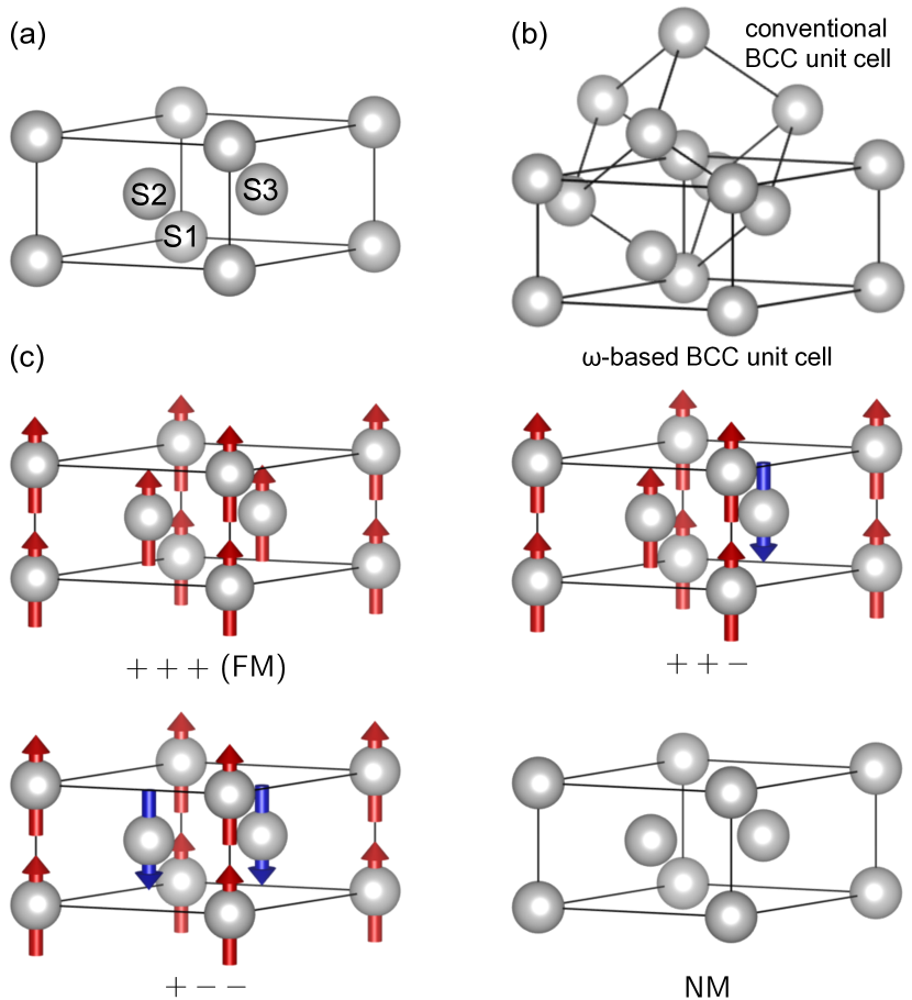
Figure 1(a) shows the primitive unit cell of the structure without considering magnetic configurations. The basis of lattice vectors for the structure , , and can be written as,
| (1) |
where and are lattice constants of the structure. The structure has three atoms, referred to as S1, S2, and S3 hereafter, inside the primitive unit cell. The atomic positions of S1, S2, and S3 are , , and in fractional coordinates, respectively. The sites S2 and S3 are crystallographycally equivalent without considering magnetic configurations. The Wyckoff positions are for the atom S1 and for the atoms S2 and S3.
The BCC structure is related to the structure by the orientation relation of and . The BCC structure can be obtained from the primitive unit cell by moving the atoms S2 and S3 to and in fractional coordinates, respectively, and by modifying the lattice constants of the structure as,
| (2) | ||||
| (3) |
where is the lattice constant of the BCC structure. Figure 1(b) shows the geometrical relation between the conventional and the “-based” unit cell of the BCC structure. From the viewpoint of the structure, it is “coherent” with the BCC when the structure has the lattice constants that satisfy Eqs. (2) and (3). In other words, if the lattice constants of the and the BCC structures exactly satisfy Eqs. (2) and (3), the structure can be obtained from the BCC by moving atoms without lattice deformation.
As well as the structure, the BCC, FCC, and HCP structures were also investigated for comparison. Four possible magnetic states, including the ferromagnetic (FM) and the nonmagnetic (NM) states, were considered for the structure. Figure 1(c) shows the considered magnetic states for the structure. For the BCC, FCC, and HCP structures, only the FM and the NM states were considered.
II.2 Electronic structures and phonons
| Number of atoms per unit cell | Mesh | |
|---|---|---|
| BCC | 2 | |
| FCC | 4 | |
| HCP | 2 | |
| 3 |
The plane-wave basis projector augmented wave method Blöchl (1994) was employed in the framework of density-functional theory Hohenberg and Kohn (1964); Kohn and Sham (1965) within the generalized gradient approximation (GGA) in the Perdew-Burke-Ernzerhof (PBE) form Perdew et al. (1996) as implemented in the VASP code Kresse (1995); Kresse and Furthmüller (1996); Kresse and Joubert (1999). A plane-wave energy cutoff of 400 eV was used. The Brillouin zones were sampled by centered meshes according to crystal structures as shown in Table 1, and the Methfessel-Paxton scheme Methfessel and Paxton (1989) with a smearing width of 0.4 eV was employed. Total energies were minimized until the energy convergences to be less than 10-8 eV. Lattice parameters were optimized under zero external stress. Magnetic moments on atoms were determined from the electron density in corresponding Voronoi cells.
Phonon frequencies of the structures were calculated based on the harmonic approximation for a lattice Hamiltonian using the finite-displacement method. Atomic displacements of 0.01 Å for the supercell of the unit cell (including 48 atoms) were used to calculate the second-order force constants. The PHONOPY code Togo and Tanaka (2015); Togo et al. (2008) was used for these phonon calculations.
III RESULTS AND DISCUSSION
III.1 Energetics for the structure of transition elements
| Magnetic state | Element | |
|---|---|---|
| BCC | FM | Mn, Fe, Co, Ni, Rh, Ir |
| FCC | FM | Fe, Co, Ni |
| HCP | FM | Co, Ni |
| FM | Fe, Co, Ni | |
| Fe | ||
| Fe |
Table 2 summarizes the magnetic states with nonzero magnetic moments found in the present calculations. Most of the nonzero magnetic moments are found for the transition elements. The FM structure is obtained for Fe, Co, and Ni. The Fe has also the and the magnetic states, which are described in Fig. 1(c). Magnetic moments converge to zero for the rest of the elements even for spin-unrestricted calculations.
| Relative energy | Volume | |||
|---|---|---|---|---|
| (meV/atom) | (Å) | (Å) | (Å3/atom) | |
| Sc | ||||
| Ti | ||||
| V | ||||
| Cr | ||||
| Mn | ||||
| Fe | ||||
| Co | ||||
| Ni | ||||
| Cu | ||||
| Y | ||||
| Zr | ||||
| Nb | ||||
| Mo | ||||
| Tc | ||||
| Ru | ||||
| Rh | ||||
| Pd | ||||
| Ag | ||||
| Lu | ||||
| Hf | ||||
| Ta | ||||
| W | ||||
| Re | ||||
| Os | ||||
| Ir | ||||
| Pt | ||||
| Au |
| Relative energy | Volume | ||||
|---|---|---|---|---|---|
| (meV/atom) | (Å) | (Å) | (Å3/atom) | ||
| Fe | FM | ||||
| NM | |||||
| Co | FM | ||||
| NM | |||||
| Ni | FM | ||||
| NM |
| Magnetic moment () | ||||
|---|---|---|---|---|
| S1 | S2 | S3 | ||
| Fe | FM | |||
| Co | FM | |||
| Ni | FM | |||
Table 3 shows calculated energies, lattice constants, and volumes of the NM structure for 27 transition elements, and Table 4 shows the values for the other magnetic states. Table 5 gives calculated magnetic moments on atoms. Volumes of the magnetic states with nonzero magnetic moments are larger than that in the NM state. The FM structure for Co and Ni are 285 and 39 meV/atom lower in energy than the NM state, respectively. For Fe, the magnetic state is the lowest in energy among the obtained magnetic states. The FM Fe is 32 meV/atom higher in energy than the magnetic state and hence is thermodynamically less favorable. The NM Fe, which is 90 meV/atom higher in energy than the state, has the highest energy among the obtained magnetic states.
| BCC | FCC | HCP | ||||||||
|---|---|---|---|---|---|---|---|---|---|---|
| NM | FM | NM | FM | NM | FM | NM | FM | |||
| Sc | ||||||||||
| Ti | ||||||||||
| V | ||||||||||
| Cr | ||||||||||
| Mn | ||||||||||
| Fe | ||||||||||
| Co | ||||||||||
| Ni | ||||||||||
| Cu | ||||||||||
| Y | ||||||||||
| Zr | ||||||||||
| Nb | ||||||||||
| Mo | ||||||||||
| Tc | ||||||||||
| Ru | ||||||||||
| Rh | ||||||||||
| Pd | ||||||||||
| Ag | ||||||||||
| Lu | ||||||||||
| Hf | ||||||||||
| Ta | ||||||||||
| W | ||||||||||
| Re | ||||||||||
| Os | ||||||||||
| Ir | ||||||||||
| Pt | ||||||||||
| Au | ||||||||||
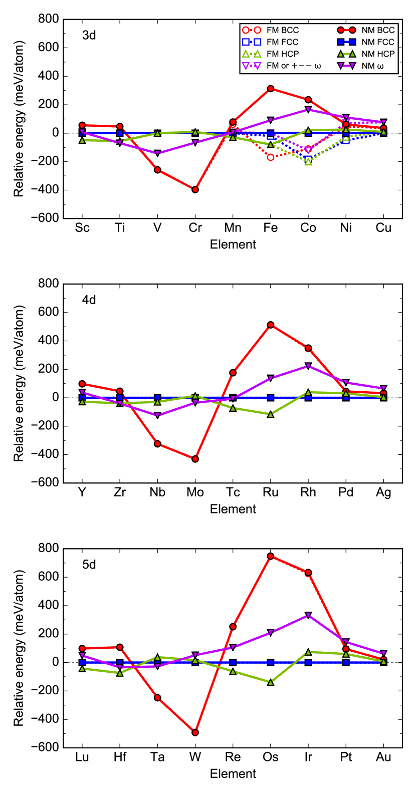
Table 6 summarizes the energies relative to that of the NM FCC structure, and Fig. 2 visualizes the result. For the NM state, most of the elements in the same groups show the same energy sequences for the investigated crystal structures. For example, the sequence for the group 8 elements (Fe, Ru, and Os) in the NM state is HCP FCC BCC in order of increasing energy. This result indicates that relative energies are roughly determined from the occupation number for orbitals for these crystal structures. This tendency has already been pointed out for the BCC, FCC, and HCP structures Skriver (1985). The present calculations reveal that the structure also follows this rule. The NM structure tends to be lower in energy than the NM FCC structure for early transition elements except for those in the group 3 (Sc, Y, and Lu) and to be higher for late transition elements. This tendency is similar to that for the NM BCC structure. The NM structure is also lower in energy than the NM BCC for the elements in the groups 3, 4, 7, 8, and 9 and higher for the elements in the other groups. For the elements in the groups 5 and 6 except for W, the NM structure is the second lowest in energy among the investigated crystal structures.
For the group 4 elements, the relative energies of the structure are low compared with the elements in the other groups. The energies of the structure relative to those of the HCP, which is observed in experiments at ambient temperature and pressure, are , 0, and 39 meV/atom for Ti, Zr, and Hf, respectively. These small energy differences indicate that the structure is thermodynamically favorable for the group 4 elements. The structure of the group 4 elements is actually observed in experiments Jamieson (1963); Xia et al. (1990); Pandey et al. (2014). Note that for Ti, our computational result shows that the structure is lower in energy than the HCP structure. This result has also been shown in a previous report Togo and Tanaka (2013) and hence is correct at least within DFT calculations using the GGA PBE functional.
The Fe is 170 meV/atom higher in energy than the FM BCC Fe, which is observed in experiments at ambient temperature and pressure. This energy difference between the structure and the state in experiments is much larger than those for the group 4 elements, which implies that the structure of Fe is thermodynamically more difficult to be formed than that of the group 4 elements. In contrast, several experimental reports have claimed that the structure can be formed in Fe-based alloys Ping and Geng (2013); Liu et al. (2015). In these experiments, the structure has been observed at twin boundaries of the BCC or as precipitates in the BCC matrix. Such kinds of structural imperfections and/or coherent stress at the interfaces are maybe required to form the Fe. Effect of solute elements is another possible reason for the formation of the structure in the Fe-based alloys. If the solute elements thermodynamically stabilize the structure more than the BCC, the Fe-based alloys may prefer to form the structure. As mentioned above, the NM structure is lower in energy than the NM BCC for the elements in the groups 3, 4, 7, 8, and 9, and hence these elements are expected to stabilize the structure more than the BCC. In addition, the FM Co is meV/atom lower in energy than the FM BCC Co, and hence Co is also expected to stabilize the structure more than the BCC.
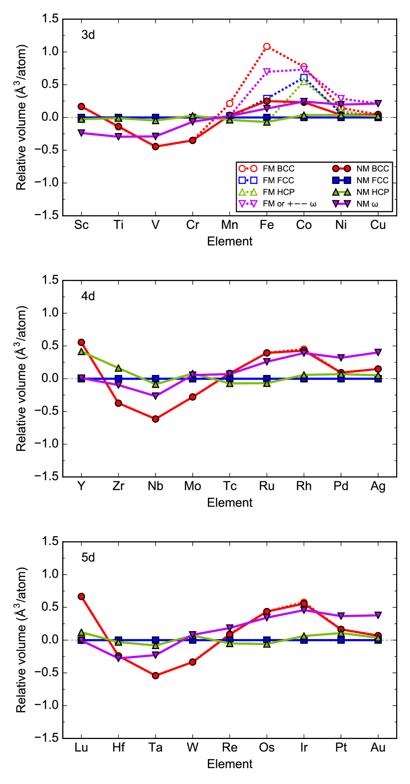
Figure 3 summarizes the calculated volumes relative to those of the NM FCC structure. For the NM state, most of the elements in the same groups show the same volume sequences for the investigated crystal structure, similarly to the case of the relative energies. The NM structure tends to be smaller in volume than the NM FCC structure for early transition elements and to be larger for late transition elements.
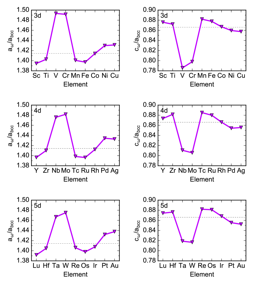
Figure 4 shows the ratios of calculated lattice constants of the NM structure to that of the NM BCC structure. Dashed holizontal lines indicate the values coherent with the BCC structure described in Eqs. (2) and (3). The values for the elements in the groups 5 and 6 are largely deviated from the coherent ones compared with the other transition elements. Therefore, the structure may be largely deformed for the elements in the groups 5 and 6 when it is coherent with the BCC structure.
III.2 Mechanical stability of the structure


Figures 5, 6, and 7 show calculated phonon dispersion relations of the NM structure for the transition elements. The elements in the same groups show similar shapes of the phonon dispersion relations. Heavier elements in the same groups tend to have smaller absolute values of phonon frequencies.
The NM structure of Ti, Mn, Fe, Co, Zr, Tc, Hf, and Re has no imaginary modes and hence is mechanically stable. The structure of Ti and Zr is actually observed at ambient temperature and pressure Jamieson (1963). Although Hf is included in the group 4 as well as Ti and Zr, the Hf has not been observed in experiments at ambient temperature and pressure Xia et al. (1990); Pandey et al. (2014). The present calculations elucidate that this is not because the Hf is mechanically unstable.
To our best knowledge, the structure has not been reported for the group 7 elements (Mn, Tc, and Re), while the structure for these elements is mechanically stable. For the group 7 elements, the energies of the structure relative to the HCP, which is the lowest in energy among the investigated crystal structures, are 35, 65, and 167 meV/atom for Mn, Tc, and Re, respectively. These energy differences are higher than those for the group 4 elements. In experiments, furthermore, Mn forms the antiferromagnetic (AFM) A12 structure as the equilibrium state at 4.2 K and at ambient pressure Shull and Wilkinson (1953). First-principles calculations suggest that the energy of the AFM A12 structure is 60 meV/atom lower in energy than the NM HCP Hafner and Hobbs (2003). As a result, we can estimate that the Mn is 95 meV/atom higher in energy than the experimental equilibrium state. These results indicate that although the structure of the group 7 elements is mechanically stable, they are thermodynamically less favorable than other crystal structures compared with the group 4 elements. Therefore, the structure of the group 7 elements is probably more difficult to be formed in experiments than that of the group 4 elements.
The structure of the elements in the groups 5 and 6 has phonon modes with imaginary frequencies and hence are mechanically unstable. Several experimental reports, however, have claimed that the structure can be formed in Ta and Mo Hsiung and Lassila (2000); Cheng et al. (2013). In these experiments, the structure has been observed in the matrix of the BCC structure, and hence structural imperfections and/or coherent stress at the interfaces between the and the BCC structures may affect the formation of the structure.

Figure 8 shows calculated phonon dispersion relations of the structure in the obtained magnetic states for Fe, Co, and Ni. Fe shows large differences among the magnetic states. The FM and the Fe have phonon modes with imaginary frequencies and hence are mechanically unstable. In contrast, the and the NM Fe have no phonon modes with imaginary frequencies and hence are mechanically stable. It has been well investigated that mechanical stability of the BCC and FCC Fe largely depend on their magnetic states such as NM, FM, and PM ones Hsueh et al. (2002); Körmann et al. (2012); Ikeda et al. (2014). The present result shows that magnetic states also affect the mechanical stability of the Fe. As shown above, the state is also the lowest in energy among the magnetic states for the structure, and hence the Fe is expected to show the state if it is formed.
The FM Co has a phonon mode with an imaginary frequency at the point (see the inset in Fig. 8), while the NM Co has no phonon modes with imaginary frequencies. Since the absolute value of the imaginary phonon frequency is very small for the FM Co, It is difficult to conclude whether the FM Co is actually mechanically unstable or not at the present moment. The Ni does not show qualitative differences between the FM and the NM states.
III.3 Energetics for the structure of binary alloys
The structure is frequently observed in alloys based on the group 4 elements Frost et al. (1954); Silcock (1958); Sass (1969); Hickman (1969); Cui and Ping (2009); Wu et al. (2014); Ping et al. (2006); Hatt et al. (1957); Hatt and Roberts (1960); Sass (1969); Jackson et al. (1970). It should be, therefore, interesting to investigate energetics of such alloys.
Since the occupation number for orbitals roughly determines the relative energies of the crystal structures of our interest, we can approximately estimate the energies of a binary alloy A1-xBx by linear interpolation as,
| (4) |
where represents the energy per atom, the symbols A and B represent the elements in the alloy, represents the concentration of the element B, and the subscript specifies the crystal structure. Note that any kinds of atomic orderings are not considered in this equation. The interpolated energy is actually the same as that of the phase-separation state of the same crystal structure. Nevertheless, this estimation is probably useful to qualitatively discuss thermodynamical stability of crystal structures for alloys with specific compositions.
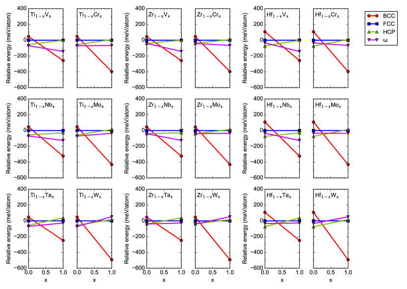
Figure 9 shows estimated energies of binary alloys composed of the elements in the group 4 and those in the groups 5 and 6. Most of the binary alloys shown in the figure have the concentration range where the structure is the lowest in energy among the investigated crystal structures. The group 4 elements are richer in these concentration ranges. In experiments, the structure is observed for the alloys based on the group 4 elements with those in the groups 5 and 6 in the concentration ranges where the group 4 elements are richer Frost et al. (1954); Hatt et al. (1957); Hatt and Roberts (1960); Silcock (1958); Jackson et al. (1970); Ping et al. (2006); Cui and Ping (2009); Hickman (1969). This experimental fact implies that the structure is relatively favorable for these alloys in the concentration ranges with rich group 4 elements. The present computational result corresponds to this experimental fact.
The structure is favorable for these alloys because of the following reason. The HCP and the structures have almost the same energies for the group 4 elements, while the HCP structure is substantially higher in energy than the structure for the elements in the groups 5 and 6 except for W. For the alloys composed of the group 4 elements and those in the groups 5 and 6, therefore, the structure is estimated to be lower in energy than the HCP. The structure is substantially lower in energy than the HCP only for the elements in the groups 5 and 6, and hence this tendency is specific for the alloys composed of the group 4 elements and those in the groups 5 and 6.
Note that even if the structure is the lowest in energy at a specific concentration, this does not mean that the structure is the equilibrium state at this concentration. When we consider a phase-separation state composed of two different crystal structures with different compositions, this phase-separation state can be lower in energy than the structure. For example, the estimated relative energy of the NM Ti0.75V0.25 to the NM FCC is meV/atom, while the mixture of 75 % NM HCP Ti and 25 % NM BCC V has the relative energy of meV/atom. In experiments, the structure in Ti-V alloys is actually thermodynamically metastable and finally decomposes into the HCP and the BCC structures with different concentrations of V atoms after sufficiently long-time aging Hickman (1968).
IV CONCLUSION
Properties of the structure are systematically investigated for 27 transition elements from the viewpoints of thermodynamical and mechanical stability using first-principles calculations. The mechanical stability is investigated in terms of phonon frequencies.
The occupation number for orbitals roughly determines relative energy and volume of the NM structure as well as the other investigated crystal structures (BCC, FCC, and HCP). For the group 4 elements (Ti, Zr, and Hf), the structure is thermodynamically favorable and is mechanically stable. For the group 7 elements (Mn, Tc, and Re), the structure is also mechanically stable, but they are thermodynamically less favorable compared with the group 4 elements. For the elements in the groups 5 and 6, the lattice constants of the structure are largely deviated from the values coherent with the BCC structure.
Several transition elements, namely Fe, Co, and Ni, have the structure with nonzero magnetic moments. For the Fe, the state is the lowest in energy among the magnetic states and is also mechanically stable. Co and Ni show the FM structure, and it is lower in energy than the NM state.
Energies of binary alloys composed of the elements in the group 4 and those in the groups 5 and 6 are estimated by linear interpolation. Most of these alloys have a concentration range where the structure is the lowest in energy among the investigated crystal structures. The group 4 elements are richer in these concentration ranges. This result corresponds to the following experimental fact; for the alloys composed of the group 4 and those in the groups 5 and 6, the structure is observed in concentration ranges where the group 4 elements are richer.
Acknowledgements.
Funding by the Ministry of Education, Culture, Sports, Science and Technology (MEXT), Japan, through Elements Strategy Initiative for Structural Materials (ESISM) of Kyoto University, is gratefully acknowledged.References
- Frost et al. (1954) P. Frost, W. Parris, L. Hirsch, J. Doig, and C. Schwartz, Trans. Am. Soc. Met. 46, 231 (1954).
- Jamieson (1963) J. C. Jamieson, Science 140, 72 (1963).
- Xia et al. (1990) H. Xia, G. Parthasarathy, H. Luo, Y. K. Vohra, and A. L. Ruoff, Phys. Rev. B 42, 6736 (1990).
- Pandey et al. (2014) K. K. Pandey, J. Gyanchandani, M. Somayazulu, G. K. Dey, S. M. Sharma, and S. K. Sikka, J. Appl. Phys. 115, 233513 (2014).
- Silcock (1958) J. Silcock, Acta Metall. 6, 481 (1958).
- Sass (1969) S. L. Sass, Acta Metall. 17, 813 (1969).
- Hickman (1969) B. Hickman, Trans. Metall. Soc. AIME 245, 1329 (1969).
- Cui and Ping (2009) C. Cui and D. Ping, J. Alloys Compd. 471, 248 (2009).
- Wu et al. (2014) S. Wu, D. Ping, Y. Yamabe-Mitarai, W. Xiao, Y. Yang, Q. Hu, G. Li, and R. Yang, Acta Mater. 62, 122 (2014).
- Ping et al. (2006) D. Ping, C. Cui, F. Yin, and Y. Yamabe-Mitarai, Scr. Mater. 54, 1305 (2006).
- Hatt et al. (1957) B. A. Hatt, J. A. Roberts, and G. I. Williams, Nature 180, 1406 (1957).
- Hatt and Roberts (1960) B. Hatt and J. Roberts, Acta Metall. 8, 575 (1960).
- Jackson et al. (1970) W. Jackson, A. Perkins, and R. Hehemann, Metall. Trans. 1, 2014 (1970).
- Hsiung and Lassila (2000) L. Hsiung and D. Lassila, Acta Mater. 48, 4851 (2000).
- Cheng et al. (2013) G. Cheng, H. Yuan, W. Jian, W. Xu, P. Millett, and Y. Zhu, Scr. Mater. 68, 130 (2013).
- Ping and Geng (2013) D. Ping and W. Geng, Mater. Chem. Phys. 139, 830 (2013).
- Liu et al. (2015) T. Liu, D. Zhang, Q. Liu, Y. Zheng, Y. Su, X. Zhao, J. Yin, M. Song, and D. Ping, Sci. Rep. 5, 15331 (2015).
- Prasetyo et al. (1976a) A. Prasetyo, F. Reynaud, and H. Warlimont, Acta Metall. 24, 1009 (1976a).
- Prasetyo et al. (1976b) A. Prasetyo, F. Reynaud, and H. Warlimont, Acta Metall. 24, 651 (1976b).
- Georgopoulos and Cohen (1981) P. Georgopoulos and J. Cohen, Acta Metall. 29, 1535 (1981).
- Yedneral and Perkas (1972) A. Yedneral and M. Perkas, Fiz. Met. Metalloved. 33, 315 (1972).
- Lecomte et al. (1985) J. Lecomte, C. Servant, and G. Cizeron, J. Mater. Sci. 20, 3339 (1985).
- Djega-Mariadassou et al. (1995) C. Djega-Mariadassou, L. Bessais, and C. Servant, Phys. Rev. B 51, 8830 (1995).
- Sikka et al. (1982) S. Sikka, Y. Vohra, and R. Chidambaram, Prog. Mater. Sci. 27, 245 (1982).
- Usikov and Zilbershtein (1973) M. P. Usikov and V. A. Zilbershtein, Phys. Status Solidi A 19, 53 (1973).
- Trinkle et al. (2003) D. R. Trinkle, R. G. Hennig, S. G. Srinivasan, D. M. Hatch, M. D. Jones, H. T. Stokes, R. C. Albers, and J. W. Wilkins, Phys. Rev. Lett. 91, 025701 (2003).
- Togo and Tanaka (2013) A. Togo and I. Tanaka, Phys. Rev. B 87, 184104 (2013).
- Ikeda et al. (2014) Y. Ikeda, A. Seko, A. Togo, and I. Tanaka, Phys. Rev. B 90, 134106 (2014).
- Momma and Izumi (2011) K. Momma and F. Izumi, J. Appl. Crystallogr. 44, 1272 (2011).
- Blöchl (1994) P. E. Blöchl, Phys. Rev. B 50, 17953 (1994).
- Hohenberg and Kohn (1964) P. Hohenberg and W. Kohn, Phys. Rev. 136, B864 (1964).
- Kohn and Sham (1965) W. Kohn and L. J. Sham, Phys. Rev. 140, A1133 (1965).
- Perdew et al. (1996) J. P. Perdew, K. Burke, and M. Ernzerhof, Phys. Rev. Lett. 77, 3865 (1996).
- Kresse (1995) G. Kresse, J. Non-Cryst. Solids 192-193, 222 (1995).
- Kresse and Furthmüller (1996) G. Kresse and J. Furthmüller, Comput. Mater. Sci. 6, 15 (1996).
- Kresse and Joubert (1999) G. Kresse and D. Joubert, Phys. Rev. B 59, 1758 (1999).
- Methfessel and Paxton (1989) M. Methfessel and A. T. Paxton, Phys. Rev. B 40, 3616 (1989).
- Togo and Tanaka (2015) A. Togo and I. Tanaka, Scr. Mater. 108, 1 (2015).
- Togo et al. (2008) A. Togo, F. Oba, and I. Tanaka, Phys. Rev. B 78, 134106 (2008).
- Skriver (1985) H. L. Skriver, Phys. Rev. B 31, 1909 (1985).
- Shull and Wilkinson (1953) C. G. Shull and M. K. Wilkinson, Rev. Mod. Phys. 25, 100 (1953).
- Hafner and Hobbs (2003) J. Hafner and D. Hobbs, Phys. Rev. B 68, 014408 (2003).
- Hsueh et al. (2002) H. C. Hsueh, J. Crain, G. Y. Guo, H. Y. Chen, C. C. Lee, K. P. Chang, and H. L. Shih, Phys. Rev. B 66, 052420 (2002).
- Körmann et al. (2012) F. Körmann, A. Dick, B. Grabowski, T. Hickel, and J. Neugebauer, Phys. Rev. B 85, 125104 (2012).
- Hickman (1968) B. Hickman, J. Inst. Met. 96, 330 (1968).