Observation of an Anisotropic Wigner Crystal
Abstract
We report a new correlated phase of two-dimensional charged carriers in high magnetic fields, manifested by an anisotropic insulating behavior at low temperatures. It appears near Landau level filling factor in hole systems confined to wide GaAs quantum wells when the sample is tilted in magnetic field to an intermediate angle. The parallel field component () leads to a crossing of the lowest two Landau levels, and an elongated hole wavefunction in the direction of . Under these conditions, the in-plane resistance exhibits an insulating behavior, with the resistance along more than 10 times smaller than the resistance perpendicular to . We interpret this anisotropic insulating phase as a two-component, striped Wigner crystal.
Low-disorder, two-dimensional (2D) systems of charged carriers, cooled to low temperatures and subjected to a strong perpendicular magnetic field () are host to a plethora of exotic, quantum many-body states Tsui et al. (1982); Shayegan (2006); Jain (2007). At odd-denominator fractional fillings of the lowest Landau level (LL), they exhibit fractional quantum Hall states (FQHSs), uniform-density, incompressible liquid phases for which the resistance vanishes as temperature approaches absolute zero Tsui et al. (1982); Shayegan (2006); Jain (2007). On the other hand, when the filling factor becomes very small (), the system condenses into an ordered array of electrons, the so-called Wigner crystal, which is insulating because it is pinned by the ubiquitous disorder potential Shayegan (2006); Jain (2007); Andrei et al. (1988); Jiang et al. (1990); Goldman et al. (1990); Shayegan (1998); Liu et al. (2014a). Yet another set of states are the anisotropic phases observed at large even-denominator fillings (e.g., ) which are believed to be nematic liquid states Lilly et al. (1999a); Du et al. (1999); Shayegan et al. (2000); Fradkin et al. (2010). The new correlated phase we report here is distinct from these states as it shows an anisotropic insulating behavior. It is manifest at low fillings (near ) in 2D hole systems (2DHSs) with a bilayer charge distribution and tilted in magnetic field to introduce a field component () parallel to the 2D plane. Curiously, the anisotropic phase forms in a relatively narrow range of tilt angles near when the two lowest energy LLs are very close in energy. Outside this range, the 2DHS is not insulating and exhibits FQHSs at numerous fillings. The conditions under which the new insulating phase appears suggest that it is an anisotropic (striped), two-component, pinned Wigner crystal (Fig. 1(a)).
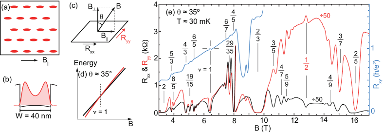
Our 2DHSs are confined to 40- and 50-nm-wide GaAs quantum wells (QWs) flanked by undoped Al0.3Ga0.7As spacer and C -doped layers, and have as grown densities cm-2. The structures were grown by molecular beam epitaxy on GaAs (001) wafers and have very high low-temperature mobilities, 100 m2/Vs. Each sample has a 4 4 mm2 van der Pauw geometry with alloyed In:Zn contacts at its four corners. We then fit it with an evaporated Ti/Au front-gate and an In back-gate to control the 2DHS density () and keep the QW symmetric. The holes in the QW have a bilayer-like charge distribution (Fig. 1(b)). The transport measurements were carried out in a dilution refrigerator with a base temperature of 30 mK, and an in-situ rotatable sample platform to induce . As illustrated in Fig. 1(c), we use to express the angle between the field and the sample plane normal, and denote the longitudinal resistances measured along and perpendicular to the direction of by and , respectively. We used low-frequency ( Hz) lock-in technique to measure the transport coefficients.
Figure 1 (e) highlights our main finding. It shows the longitudinal ( and ) and Hall () magneto-resistance traces, measured for a 2DHS confined to a 40-nm-wide GaAs QW at cm-2 and . Starting at T, both and rapidly increase; note the 50 times change of scale for and above 8 T Note (1); Goldman et al. (1993); Sajoto et al. (1993). Most remarkably, near , is 25 k while and, as we will show shortly, both and exhibit an insulating behavior. To probe the origin of this anisotropic insulating phase (IP), we present several experimental observations.
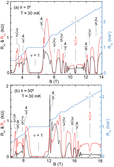
Data of Fig. 2, which were taken at and , demonstrate that the anisotropic IP seen in Fig. 1(e) occurs near a crossing of the lowest two LLs (Fig. 1(d)). The crossing is signaled by a profound weakening of the integer QHS at intermediate Graninger et al. (2011); Liu et al. (2015). As is evident in Fig. 2, traces taken at both and show a strong integer QHS at , with a very wide resistance plateau and large excitation gap K. In contrast, at intermediate angle (Fig. 1(e)), the QHS becomes much weaker ( K) and has a very narrow plateau.
The evolution of the FQHSs in Figs. 1(e) and 2 are also consistent with a LL crossing occurring near when . In Fig. 2 traces there are numerous strong FQHSs at the well-known, “standard” fillings ( is an integer) Jain (2007). In Fig. 1(e) data, however, near there are uncharacteristically strong FQHSs at the even-numerator fillings , 6/5, 6/7, and 4/5. This is similar to what is seen in bilayer 2D electron systems (2DESs) with extremely small energy separation between the lowest two LLs Manoharan et al. (1997), and implies that these are two-component FQHSs, each component having half of the total filling. In Fig. 1(e) we also observe FQHSs at very unusual fillings such as and 29/35. Such states were seen in Ref. Manoharan et al. (1997) when the lowest two LLs are nearly degenerate, and were interpreted as “imbalanced” two-component FQHSs: for example, the FQHS has fillings 2/3 and 3/5 for its two components. In Fig. 2, we also observe strong FQHSs at the even-denominator filling . This FQHS is seen in 2DESs and 2DHSs confined to wide GaAs QWs Suen et al. (1992, 1994); Shabani et al. (2013); Liu et al. (2014b). It is likely the state, a two-component FQHS stabilized by strong and comparable interlayer and intralayer interactions which are prevalent at Note (2).
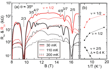
Next we focus on the anisotropic IP seen at . Figure 3 captures the insulating behavior of this phase near . Both and increase as temperature is decreased but, as can be best seen in Fig. 3(b), is about 10 times larger than . Before discussing this anisotropic behavior, it is instructive to first briefly review the IPs seen in 2D systems at low fillings.
It is well established that in very clean 2D systems of charged carriers, at very small ( for electrons and for holes) the FQHSs give way to IPs which are believed to be Wigner crystal (WC) phases that are pinned by the small but ubiquitous disorder Lozovik and Yudson (1975); Andrei et al. (1988); Jiang et al. (1990); Goldman et al. (1990); Santos et al. (1992a, b); Li et al. (1997); Shayegan (1998). For both 2D electron and hole systems in wide, symmetric GaAs QWs, the charge distribution becomes more bilayer-like with increasing density and the IP sets in at progressively larger Manoharan et al. (1996); Liu et al. (2014b); Hatke et al. (2015). These IPs are believed to be bilayer WC states which, thanks to the additional layer/subband degree of freedom, are stabilized at relatively large compared to the single-layer systems. For example, in 2DHSs confined to a 40-nm-wide QW with cm-2 Liu et al. (2014b), an IP is observed near . All the IPs described above are isotropic, and were observed in the absence of Note (3); Hasdemir et al. (2015).
To discuss the likely origin of the anisotropic IP we observe near , we focus on its key attributes:
(i) It is a collective state. There are numerous FQHSs near in Fig. 1(e), e.g., at = 2/5, 3/7, 4/9, 3/5, 4/7, 5/9. These correlated states are much weaker than the FQHSs seen at the same fillings in Fig. 2 traces, but their mere presence in Fig. 1(e) strongly suggests that correlations are prevalent near where the IP reigns. Also worth emphasizing is that in Fig. 2 traces there are very strong FQHSs near and even at . It is very unlikely that at the intermediate tilt angle of Fig. 1(e) interactions would disappear and the ground state become of single-particle origin.
(ii) It is a two-component state. It is clear that the anisotropic IP is observed near a LL crossing, and Fig. 2 traces, which were taken far from the LL crossing, do not show insulating behavior near . This implies that the presence of two nearly degenerate LLs plays a crucial role for its stability. Also, theoretical calculations rule out any single-component WC near Archer et al. (2013). The anisotropic IP we observe at is thus likely to have a two-component origin. In Fig. 3(a), the existence of minima at , 3/7, 3/5, and their deepening (relative to the insulating background resistance) at lower temperatures, signal a close competition between a reentrant two-component WC phase and the FQHSs. We add that, whether isotropic or anisotropic, one-component or two-component, the observation of an IP near the crossing of two LLs is by itself unprecedented.
(iii) It is not a nematic liquid state. One might naively conclude that the anisotropy we report resembles the one observed at higher half-filled LLs, and believed to signal nematic electron phases Lilly et al. (1999a); Du et al. (1999); Shayegan et al. (2000); Fradkin and Kivelson (1999); Fradkin et al. (2010). But this is incorrect, as there are two major, qualitative differences. First, nematic phases are liquid states: while in-plane transport becomes anisotropic, and do not diverge at low temperatures; instead they remain finite and in fact the resistance along the “easy axis” direction decreases as temperature is lowered and attains extremely small values Lilly et al. (1999a); Du et al. (1999). This is very different from the insulating behavior and the large values we measure for both and . Second, in the case of -induced nematic phases, the “hard axis” is typically along Pan et al. (1999); Lilly et al. (1999b). We observe the opposite behavior: the resistance along () is smaller than in the perpendicular direction Note (4).
Based on the above observations, we associate the IP observed in Fig. 1(e) with a pinned, anisotropic WC. We suggest that the anisotropy originates from the strongly distorted shape of the hole charge distribution induced by , as schematically depicted in Fig. 1(a). Because of the finite thickness of the hole layer in our sample, couples to the out-of-plane (orbital) motion of the carriers, and squeezes the charge distribution in the direction perpendicular to (see Fig. 1(a)). Such distortions have been recently documented for carriers near , and also for composite fermions at high Kamburov et al. (2012, 2013, 2014). An elongated charge distribution can lead to anisotropic interaction, and provides a natural explanation for the anisotropic IP we observe in terms of a pinned, striped WC as shown in Fig. 1(a) Note (5, 6); Wan and Bhatt (2002). Moreover, it is consistent with the experimental observation that the transport “easy axis” is along (i.e., ), as intuitively the excited quasi-particles (at finite temperatures) should have a higher hopping rate in the direction of charge distribution elongation.
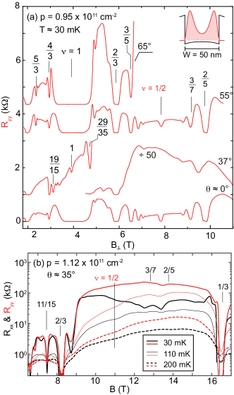
Data taken on the 50-nm-wide QW (Fig. 4) corroborate Figs. 1-3 data and our above conclusions, and reveal new information. In Fig. 4(a) we show traces at density cm-2 at different angles. Qualitatively similar to the data of Figs. 1 and 2, the traces at and appear normal and exhibit a very strong integer QHS and numerous FQHSs at standard fillings as well as at . The trace, however, shows an IP near . The same trace also indicates a weak minimum near and other features, e.g. FQHSs at and 29/35, indicating that the two lowest LLs are near a coincidence. Traces taken at and slightly higher density, presented in Fig. 4(b), reveal that and that both and show insulating behavior near , similar to the 40-nm-wide QW data of Fig. 3.
The smaller density in the 50-nm QW sample allows us to make measurements at higher tilt angles. As seen in the top trace of Fig. 4(a), taken at , an IP reappears at high , past . We believe this IP signals the onset of the 2DHS splitting into a bilayer system, similar to what is seen in 2DESs confined to wide QWs at very large tilt angles Note (7).
The results we report here attest to the extremely rich physics of 2DHSs confined to wide GaAs QWs. In these systems one can cause a crossing of the lowest two LLs by either changing the density Liu et al. (2014c) or titling the sample in magnetic field Graninger et al. (2011); Liu et al. (2014c, 2015). Depending on the sample parameters, the crossing can destroy the ordinary QHSs, both at integer and fractional fillings, and bring to life unusual phases such as a FQHS at Liu et al. (2014c) or, as we have shown here, an anisotropic IP signaling a two-component, striped Wigner crystal.
Acknowledgements.
We acknowledge support by the DOE BES (DE-FG02-00-ER45841) grant for measurements, and the NSF (Grants DMR-1305691 and MRSEC DMR-1420541), the Gordon and Betty Moore Foundation (Grant GBMF4420), and Keck Foundation for sample fabrication and characterization. We thank R.N. Bhatt, E. Fradkin, J.K. Jain, and S.A. Kivelson for illuminating discussions, and R. Winkler for providing the charge distribution and potential calculations shown in Figs. 1(b) and 4(a). A portion of this work was performed at the NHMFL, which is supported by the NSF Cooperative Agreement No. DMR-1157490, the State of Florida, and the DOE. We thank S. Hannahs, G. E. Jones, T. P. Murphy, E. Palm, A. Suslov, and J. H. Park for technical assistance.References
- Tsui et al. (1982) D. C. Tsui, H. L. Stormer, and A. C. Gossard, Phys. Rev. Lett. 48, 1559 (1982).
- Shayegan (2006) M. Shayegan, in High Magnetic Fields: Science and Technology, Vol. 3, edited by F. Herlach and N. Miura (World Scientific, Singapore, 2006) pp. 31–60.
- Jain (2007) J. K. Jain, Composite Fermions (Cambridge University Press, Cambridge, UK, 2007).
- Andrei et al. (1988) E. Y. Andrei, G. Deville, D. C. Glattli, F. I. B. Williams, E. Paris, and B. Etienne, Phys. Rev. Lett. 60, 2765 (1988).
- Jiang et al. (1990) H. W. Jiang, R. L. Willett, H. L. Stormer, D. C. Tsui, L. N. Pfeiffer, and K. W. West, Phys. Rev. Lett. 65, 633 (1990).
- Goldman et al. (1990) V. J. Goldman, M. Santos, M. Shayegan, and J. E. Cunningham, Phys. Rev. Lett. 65, 2189 (1990).
- Shayegan (1998) M. Shayegan, in Perspectives in Quantum Hall Effects, edited by S. D. Sarma and A. Pinczuk (Wiley, New York, 1998) pp. 343–383.
- Liu et al. (2014a) Y. Liu, H. Deng, M. Shayegan, L. N. Pfeiffer, K. W. West, and K. W. Baldwin, arXiv:1410.3435 (2014a).
- Lilly et al. (1999a) M. P. Lilly, K. B. Cooper, J. P. Eisenstein, L. N. Pfeiffer, and K. W. West, Phys. Rev. Lett. 82, 394 (1999a).
- Du et al. (1999) R. R. Du, D. C. Tsui, H. L. Stormer, L. N. Pfeiffer, K. W. Baldwin, and K. W. West, Solid State Communications 109, 389 (1999).
- Shayegan et al. (2000) M. Shayegan, H. C. Manoharan, S. J. Papadakis, and E. P. D. Poortere, Physica E: Low-dimensional Systems and Nanostructures 6, 40 (2000).
- Fradkin et al. (2010) E. Fradkin, S. A. Kivelson, M. J. Lawler, J. P. Eisenstein, and A. P. Mackenzie, Annu. Rev. Condens. Matter Phys. 1, 153 (2010).
- Note (1) In Fig. 1(e), the anomalous drop in for T is an artifact due to the mixing of the longitudinal resistances which attain very high values Goldman et al. (1993); Sajoto et al. (1993).
- Goldman et al. (1993) V. J. Goldman, J. K. Wang, B. Su, and M. Shayegan, Phys. Rev. Lett. 70, 647 (1993).
- Sajoto et al. (1993) T. Sajoto, Y. P. Li, L. W. Engel, D. C. Tsui, and M. Shayegan, Phys. Rev. Lett. 70, 2321 (1993).
- Graninger et al. (2011) A. L. Graninger, D. Kamburov, M. Shayegan, L. N. Pfeiffer, K. W. West, K. W. Baldwin, and R. Winkler, Phys. Rev. Lett. 107, 176810 (2011).
- Liu et al. (2015) Y. Liu, S. Hasdemir, M. Shayegan, L. N. Pfeiffer, K. W. West, and K. W. Baldwin, Phys. Rev. B 92, 195156 (2015).
- Manoharan et al. (1997) H. C. Manoharan, Y. W. Suen, T. S. Lay, M. B. Santos, and M. Shayegan, Phys. Rev. Lett. 79, 2722 (1997).
- Suen et al. (1992) Y. W. Suen, L. W. Engel, M. B. Santos, M. Shayegan, and D. C. Tsui, Phys. Rev. Lett. 68, 1379 (1992).
- Suen et al. (1994) Y. W. Suen, H. C. Manoharan, X. Ying, M. B. Santos, and M. Shayegan, Phys. Rev. Lett. 72, 3405 (1994).
- Shabani et al. (2013) J. Shabani, Y. Liu, M. Shayegan, L. N. Pfeiffer, K. W. West, and K. W. Baldwin, Phys. Rev. B 88, 245413 (2013).
- Liu et al. (2014b) Y. Liu, A. L. Graninger, S. Hasdemir, M. Shayegan, L. N. Pfeiffer, K. W. West, K. W. Baldwin, and R. Winkler, Phys. Rev. Lett. 112, 046804 (2014b).
- Note (2) In Fig. 2(a) we also see a developing FQHS at , which can be interpreted as the particle-hole counterpart of the FQHS. Also, the weak QHS at in Fig. 1(e) is likely the two-component state Liu et al. (2015).
- Lozovik and Yudson (1975) Y. Lozovik and V. Yudson, JETP Lett. 22, 11 (1975).
- Santos et al. (1992a) M. B. Santos, Y. W. Suen, M. Shayegan, Y. P. Li, L. W. Engel, and D. C. Tsui, Phys. Rev. Lett. 68, 1188 (1992a).
- Santos et al. (1992b) M. B. Santos, J. Jo, Y. W. Suen, L. W. Engel, and M. Shayegan, Phys. Rev. B 46, 13639 (1992b).
- Li et al. (1997) C.-C. Li, L. W. Engel, D. Shahar, D. C. Tsui, and M. Shayegan, Phys. Rev. Lett. 79, 1353 (1997).
- Manoharan et al. (1996) H. C. Manoharan, Y. W. Suen, M. B. Santos, and M. Shayegan, Phys. Rev. Lett. 77, 1813 (1996).
- Hatke et al. (2015) A. T. Hatke, Y. Liu, L. W. Engel, M. Shayegan, L. N. Pfeiffer, K. W. West, and K. W. Baldwin, Nature Communications 6, 7071 (2015).
- Note (3) Termination of the FQHSs by IPs at low fillings has also been reported in fixed-density 2DESs confined to wide GaAs QWs when a large is applied Hasdemir et al. (2015). In this case, couples to the orbital (out-of-plane) motion of electrons and renders the system progressively more bilayer-like with increasing Hasdemir et al. (2015).
- Hasdemir et al. (2015) S. Hasdemir, Y. Liu, H. Deng, M. Shayegan, L. N. Pfeiffer, K. W. West, K. W. Baldwin, and R. Winkler, Phys. Rev. B 91, 045113 (2015).
- Archer et al. (2013) A. C. Archer, K. Park, and J. K. Jain, Phys. Rev. Lett. 111, 146804 (2013).
- Fradkin and Kivelson (1999) E. Fradkin and S. A. Kivelson, Phys. Rev. B 59, 8065 (1999).
- Pan et al. (1999) W. Pan, J.-S. Xia, V. Shvarts, D. E. Adams, H. L. Stormer, D. C. Tsui, L. N. Pfeiffer, K. W. Baldwin, and K. W. West, Phys. Rev. Lett. 83, 3530 (1999).
- Lilly et al. (1999b) M. P. Lilly, K. B. Cooper, J. P. Eisenstein, L. N. Pfeiffer, and K. W. West, Phys. Rev. Lett. 83, 824 (1999b).
- Note (4) Some anisotropy is also seen in Fig. 2 traces. The rather small (less than a factor of two) anisotropy observed in Fig. 2(a) () near possibly comes from the sample’s van der Pauw geometry and the contacts’ misalignment. The anisotropy becomes larger, about a factor of four, in Fig. 2(b) (). The origin of this increased anisotropy is likely the deformation (elongation) of the hole charge distribution along (Fig. 1(a)), as we discuss later in the manuscript.
- Kamburov et al. (2012) D. Kamburov, M. Shayegan, R. Winkler, L. N. Pfeiffer, K. W. West, and K. W. Baldwin, Phys. Rev. B 86, 241302 (2012).
- Kamburov et al. (2013) D. Kamburov, Y. Liu, M. Shayegan, L. N. Pfeiffer, K. W. West, and K. W. Baldwin, Phys. Rev. Lett. 110, 206801 (2013).
- Kamburov et al. (2014) D. Kamburov, M. A. Mueed, M. Shayegan, L. N. Pfeiffer, K. W. West, K. W. Baldwin, J. J. D. Lee, and R. Winkler, Phys. Rev. B 89, 085304 (2014).
- Note (5) An “insulating stripe-crystal” phase has indeed been discussed theoretically for an interacting 2D system in the excited () LL Fradkin and Kivelson (1999).
- Note (6) The role of effective mass anisotropy for 2D WC states has also been discussed in Ref. Wan and Bhatt (2002).
- Wan and Bhatt (2002) X. Wan and R. N. Bhatt, Phys. Rev. B 65, 233209 (2002).
- Note (7) See, e.g., the trace in Fig. 1 of Ref. Hasdemir et al. (2015).
- Liu et al. (2014c) Y. Liu, S. Hasdemir, D. Kamburov, A. L. Graninger, M. Shayegan, L. N. Pfeiffer, K. W. West, K. W. Baldwin, and R. Winkler, Phys. Rev. B 89, 165313 (2014c).