Mechanical bound state in the continuum for optomechanical microresonators
Abstract
Clamping loss limits the quality factor of mechanical mode in the optomechanical resonators supported with the supporting stem. Using the mechanical bound state in the continuum, we have found that the mechanical clamping loss can be avoided. The mechanical quality factor of microsphere could be achieved up to for a specific radius of the stem, where the different coupling channels between the resonator and supporting stem are orthogonal to each other. Such mechanism is proved to be universal for different geometries and materials, thus can also be generalized to design the high quality mechanical resonators.
I Introduction
The optomechanical interactions, which have been motivated more than thirty years Ref_1 ; Ref_2 ; Opto_1 ; Opto_2 , take place via either the radiation pressure and gradient forces induced by the optical fields Radiation_1 ; Radiation_3 ; Li2008 or nonlinear processes such as Brillouin scattering Brillouin_1 ; Brillouin_2 . These interactions play a crucial role in the quantum state transfer between light and mechanical motion Hybrid ; Transducer2 ; Transducer1 . The ubiquitous nature of mechanical freedom degrees can enable a macroscopic mechanical oscillator to couple to nearly all types of quantum systems, including charge, spin, atomic, and superconducting qubits, as well as photons at nearly any wavelength Treutlein2014 ; Kurizki2015 . The radiation-pressure-induced coherent mechanical oscillations in whispering gallery mode (WGM) microresonator have been observed in experiment about a decade ago Radiation_3 . Such optomechanical resonators have been used to obtain a variety of coherent optical processes, such as optomechanical induced transparency (OMIT) OMIT_1 ; OMIT_2 ; OMIT_3 , optomechanical light storage Storage , and coherent optical wavelength conversion OMIT_3 ; Conversion_1 . Radiation pressure cooling of mechanical oscillators to their ground states has also been realized experimentally in these optical resonators Cooling_1 ; Cooling_2 . In all these applications, the intrinsic mechanical quality () factor is important, which limits the phonon lifetime and the fidelity of interconversion between phonon and other excitations.
The dominate origins of mechanical energy dissipation can be divided into three categories: fluid-structure interactions, material damping and clamping damping Cleland ; limited_1 . There exists different strategies to reduce the relevant dampings. To eliminate the fluid-structure interactions or air damping, the most effective strategy is to place the device in the low pressure vacuum chamber Limited_2 . For the material damping, controlling the type, distribution, density of defects, the operating temperature, and designing material are usually considered limited_1 . Although the material damping face the fundamental technique challenges, the clamping damping can be eliminated by clever designs, such as supporting the resonator at its nodal points limited_6 ; limited_9 or surrounding the resonator by phononic band-gap structures limited_13 .
Here, we propose the mechanical bound state in the continuum (BIC) to reduce the clamping damping to show the improved mechanical in the silica microsphere. The BIC, which was first proved by Von Neuman and Wigner in 1929 BIC_1 , has been demonstrated in electronic and photonic structures BIC_3 ; BIC_4 ; BIC_5 ; BIC_6 ; Hus ; BIC_2 . Similar to the optical BIC that creates two dissipation channels and controls their phases to cancel each other BIC_2 , the elastic wave dissipation through different polarizations can be eliminated in appropriate structure. By extending the BIC phenomena to the mechanical system, we demonstrate the leakage of spherical vibration to the supporting stem can be canceled. The mechanical Q factor limited by the clamping loss can be as high as (limited by the precision of simulation) for BIC with the appropriate supporting stem. We believe that the BIC is a novel and efficient method for inhibiting the mechanical clamping loss, the mechanism is universal and can be used for the designing of other phononic structures to overcome the phonon dissipation.
II Model
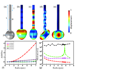
The basic principle of the mechanical BIC is illustrated by the simple microsphere on stem structure (Fig. 1(a)). In the experiment, the silica microsphere is normally fabricated by a laser beam and supported at the end of the fiber tip SphereReview . In past decades, the silica microsphere on fiber stem has been extensively studied in experiment due to its ultrahigh optical factor (up to high_q ; high_Q ) and easy fabrication. Thus, we build the model in the COMSOL multiphysics, as shown in Fig. 1(a). The microsphere with radius of is supported by a stem with radius of . The stem length is with a perfectly matched layer of . The parameters of the model are =. Similarly with the optical modes SphereReview , the acoustic waves in silica microsphere can be identified by radial (), orbital (), and azimuth () numbers. In bulk materials, there are three types of elastic wave for different polarizations, including pressure wave (displacement along propagation direction), flexural wave (out-of-plane transverse displacement) and shear wave (in-plane transverse displacement) Cleland . In spheres, the modes are divided into two categorieslimited_0 : spheroidal and torsional modes, which are hybridized flexural and pressure waves and pure shear waves, respectively. For optomechanical applications, we are mostly interested in those spheroidal modes since the volume change of torsional mode is zero. In addition, it’s also recently demonstrated that the spheroidal mode can couple with magnons efficiently magnon .
Shown in Figs. 1(b)-(e) are the typical spheroidal modes (), (), () and (), respectively. From the simulated distributions of deformation, we find that there are three different clamping conditions: the spherical vibration coupling with the pressure wave in the supporting stem for () and () modes [Figs. 1(b) and (c)], the excited flexural wave in the stem for () [Fig. 1(d)], and almost no elastic wave dissipation in the stem for () mode. The intuitive explanation of the excited pressure wave for the is that the motion of the sphere is at the polar point (antinode), or pure radial motion at the clamping point, which can only compress and stretch the stem in -direction (cylindrical coordinate for stem). In contrast, for () mode with , there is only vibration along the equator of the sphere (we may call this type of mode as mechanical WGMs), so there is no displacement at the polar point, then the loss is zero. When varying the stem size, we can see that the frequencies of () and () modes change a lot while the mechanical factors decrease monotonously. It indicates the coupling between stem and these modes proportional to the area of the cross-section of the stem (). For the mechanical WGMs, both the frequency and mechanical remain constant for different , respectively, and the mechanical is larger than with small fluctuations due to the numerical errors.
The () mode shows very different and interesting behavior from the other two type of modes. From the field distributions, we can see that at the contact point of the sphere and the stem, there is zero mean displacement in -direction but non-zero displacement in transverse direction. The flexural motion (out-of-plane transverse displacement) of stem shows similar displacement in -direction and transverse direction. Shown in Fig. 1(g), there is a singular peak for () mode at . At the peak, the mechanical with the number limited by the precision of numerical simulation.
III Mechanical BIC
For the purpose of optomechanical interaction in the sphere, we would choose the two types of modes, () in Fig. 1(d) and () in Fig. 1(e), in our experiments. The () mode shows zero net displacement in the equator and non-zero orbit angular momentum, thus can only couple with light through the Brillouin scattering process Brillouin_1 ; Brillouin_2 , which requires two optical modes to satisfy the phase matching and energy conservation relations. The mechanical loss of the breath type of modes, () in Fig. 1(b) and () in Fig. 1(c), are very large due to the strongest radiation pressure coupling and the pressure wave leakage to the stem. To achieve high mechanical Q factor for those modes, the supporting stem should be thinner than . However, the system would be very fragile and impractical for thin stems, the () mode is a better choice with much high mechanical Q factor and thick stem size. The singular high-Q peak in the () mode is useful and the details about the mechanism of the phenomena are explained in the following.
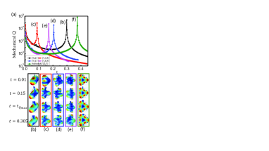
In Fig. 2(a), the mechanical Q of () mode profiles with different stem to sphere radius ratio . At the singular point, the mechanical Q exponentially decays with the deflection of the optimal ratio. This extremum of the mechanical Q means that the propagating flexural wave in the stem can not be excited by the sphere vibration. We notice that there are two polarizations of displacement involved into the coupling between the spheroidal mode of sphere and flexural mode of stem: the radial displacement and tangent displacement (in respect to the sphere). The polarization of the sphere combines the two displacements and it is the same with the stem. Therefore, it is possible that the polarization of the sphere from one channel is orthogonal to the polarization of the stem from the other channel in the joint, which realizes the mechanical BIC and forbids the elastic wave leakage to the continuum waves of stem.
Similar principle should also work for other mechanical modes, such as all the higher order modes. To verify such mechanical BIC mechanism in the spherical mechanical microresonator, the higher order modes with are studied and the results are plotted in Figs. 2(a) and (c)-(e). All these modes show similar singular high mechanical Q factors with specific . At those optimal , the displacement of stem exponentially decreases with the distance to the sphere, which indicates that the propagating elastic wave in the stem is not excited. We should note that the BIC for () is not supported in the silica sphere, since the spheroidal mode couples to the high loss torsional mode by the perturbation of stem. Therefore, we modified the Young’s modulus to 50 GPa and the Poisson ratio to 0.12, and plotted the results in Figs. 2(a).
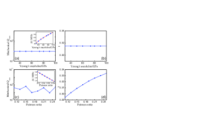
Then, we testify the existence of the BIC for different material properties. As shown in Fig. 3, the mechanical and the eigenfrequency for mode are changed according to Young’s modulus and Poisson ratio of the material. Firstly, for R=12, the eigenfrequency increases with the Young’s modulus rising from to GPa. The mechanical for BIC retains up to . Due to the precision limited by numerical simulation, the fluctuation of the mechanical above is unconspicuous. We find that the optimal ratio is stable as the Young modulus of the structure adds up. As shown in Figs. 3(c) and (d). When varying the Poisson ratio from to , the eigenfrequency decreases, and rises up while the mechanical remains high.
Further generalization of such principle can apply to the quasi-2D structure, such as the microdisk suspended by attaching to an auxiliary beamring resonator . Similar to the microsphere, the 3rd order mode in Figs. 2(f) (similar to spherical coordinator, this mode in disk can be identified as () in respect to the mode order in the radial, azimuthal and thickness direction) shows in-plane standing wave profile along the boundary of the disk. The mode is combined radial and tangential displacements, and the corresponding leaking wave in beam is the in-plane flexural wave. Very similar to the microsphere case, we observe the leakage forbidden by changing the beam width, which leads to the BIC phenomenon in structures on photonic chips.
IV Discussions
All of these results confirm the universality of the mechanism of mechanical BIC, which is applicable to other material and structures. For practical applications of the mechanical BIC, we should also consider the imperfections of the fabricated microstructures. For example, during the fabrication of the silica microsphere, due to the surrounding environment perturbations (such as wind and vibrations) and gravitation force, the sphere may not be perfectly spherical and the stem may not point to the center of sphere.
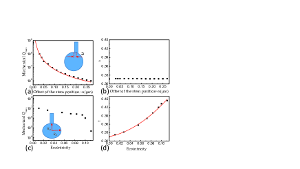
Figs. 4(a) shows that the achievable mechanical for BIC reduces with the increased offset of the stem. When the offset is for , the mechanical value limited by the clamping loss gets down to . Therefore, the symmetry is important for the high mechanical . In Figs. 4(b), the optimal is almost constant for different offsets. For the gravity induced small eccentricity of the microsphere, the achievable mechanical also reduces, as shown in Figs. 4(c). Define the eccentricity as , with and are long and short axes. There is a critical eccentricity around , beyond that the mechanical reduces dramatically to be smaller than . The results in Figs. 4(d) indicate that the optimal rate rises quickly as the eccentricity grows up. In practical experiment, the gravity induced eccentricity is usually around , which still permits be larger than one million.
In previous experiments, the measured mechanical Q of silica microsphere is limited to be in vacuum and cryogenic temperatures Cooling_1 ; Cooling_2 . It is believed that it is the material limitation, due to the absorption of two-level system (TLS) in non-crystal silica. However, such limitation can be resolved by pump the system to saturate the TLS at low temperature TLS . By this technique, the million level of mechanical BIC is possible for silica whispering gallery microresonators and will promote the single photon level optomechanics experiments. For example, the lifetime for mechanical mode with and Hz is , which is one excellent candidate for quantum memory.
V Conclusion
The mechanical bound states in the continuum are studied, whose elastic energy loss through clamping structures is forbidden. The intrinsic mechanism is that the polarization of the vibration on the mechanical resonator is orthogonal to that of the supporting stem, thus cancels the elastic wave radiation through changing the radius of the stem. The detailed studies on different mechanical modes, different mechanical resonator structures and materials confirm the universality of the mechanical bound states in the continuum. Therefore, the mechanism studied in this paper can be used for the design of other mechanical resonators, in the field of optomechanics and electromechanics.
Acknowledgment
CLZ thanks H. Wang for stimulating discussions. The work was supported by the Strategic Priority Research Program (B) of the Chinese Academy of Sciences (Grant No. XDB01030200), National Basic Research Program of China (Grant Nos. 2011CB921200 and 2011CBA00200) and the National Natural Science Foundation of China (Grant Nos. 61308079 and 61505195), Anhui Provincial Natural Science Foundation (Grant No. 1508085QA08), the Fundamental Research Funds for the Central Universities.
References
- (1) T.V. B. Braginsky, Measurement of Weak Forces in Physics Experiments (Univ. of Chicago Press, 1977).
- (2) M. I. Dykman, “Heating and cooling of local and quasilocal vibrations by a nonresonance field,” Soviet Phys. - Solid State 20, 2264-2272 (1978).
- (3) M. Aspelmeyer, P. Meystre, and K. Schwab, “Quantum optomechanics,” Phys. Today 65(7), 29 (2012).
- (4) M. Aspelmeyer, T. J. Kippenberg, and F. Marquard, “Cavity optomechanics,” Rev. Mod. Phys. 86, 1391-1452 (2014).
- (5) A. Dorsel, J. D. Mccullen, P. Meystre, E. Vignes, and H. Walther, “Optical Bistability and Mirror Confinement Induced by Radiation Pressure,” Phys. Rev. Lett. 51, 1550-1553 (1983).
- (6) T. J. Kippenberg, H. Rokhsari, T. Carmon, A. Scherer, and K. J. Vahala, “Analysis of radiation-pressure induced mechanical oscillation of an optical microcavity,” Phys. Rev. Lett. 95, 033901 (2005).
- (7) M. Li, W. H. P. Pernice, C. Xiong, T. Baehr-Jones, M. Hochberg, and H. X. Tang, “Harnessing optical forces in integrated photonic circuits,” Nature 456, 480–484 (2008).
- (8) G. Bahl, M. Tomes, F. Marquardt, and T. Carmon, “Observation of spontaneous Brillouin cooling,” Nature Phys. 8, 203-207 (2012).
- (9) C. H. Dong, Z. Shen, C. L. Zou, Y. L. Zhang, W. Fu, and G. C. Guo, “Brillouin-scattering-induced transparency and non-reciprocal light storage,” Nature Commun. 6, 6193 (2015).
- (10) C.-H. Dong, Y.-D. Wang, and H.-L. Wang, “Optomechanical Interfaces for Hybrid Quantum Networks,” National Science Review 2, 510 (2015).
- (11) K. Stannigel, P. Rabl, A. S. Sorensen, P. Zoller, and M. D. Lukin, “Optomechanical Transducers for Long-Distance Quantum Communication,” Phys. Rev. Lett. 105, 220501 (2010).
- (12) L. Tian, “Optoelectromechanical transducer: Reversible conversion between microwave and optical photons,” Ann. Phys. 527, 1–14 (2015).
- (13) P. Treutlein, C. Genes, K. Hammerer, M. Poggio, and P. Rabl, “Hybrid Mechanical Systems,” in Cavity Optomechanics, M. Aspelmeyer, T. J. Kippenberg, and F. Marquardt, eds. (Springer Berlin Heidelberg, 2014), pp. 327–351.
- (14) G. Kurizki, P. Bertet, Y. Kubo, K. M lmer, D. Petrosyan, P. Rabl, and J. Schmiedmayer, “Quantum technologies with hybrid systems,” Proc. Natl. Acad. Sci. 112, 3866–3873 (2015).
- (15) S. Weis, R. Riviere, S. Deleglise, E. Gavartin, O. Arcizet, A. Schliesser, and T. J. Kippenberg, “Optomechanically induced transparency,” Science 330, 1520 (2010).
- (16) C. H. Dong, V. Fiore, M. C. Kuzyk, and H. Wang, “Optomechanical dark mode,” Science 338, 1609 (2012).
- (17) Y. Liu, M. Davan o, V. Aksyuk, and K. Srinivasan, “Electromagnetically induced transparency and wideband wavelength conversion in silicon nitride microdisk optomechanical resonators,” Phys. Rev. Lett. 110, 223603 (2013).
- (18) V. Fiore, Y. Yang, M. C. Kuzyk, R. Barbour, L. Tian, and H. Wang, “Storing optical information as a mechanical excitation in a silica optomechanical resonator,” Phys. Rev. Lett. 107, 133601 (2011).
- (19) C. H. Dong, V. Fiore, M. C. Kuzyk, L. Tian, and H. L. Wang, “Optical wavelength conversion via optomechanical coupling in a silica resonator,” Annalen Der Physik 527, 100-106 (2015).
- (20) Y. S. Park, and H. Wang, “Resolved-sideband and cryogenic cooling of an optomechanical resonator,” Nature Phys. 5, 489 (2009).
- (21) R. Riviere, S. Deleglise, S. Weis, E. Gavartin, O. Arcizet, A. Schliesser, and T. J. Kippenberg, “Optomechanical sideband cooling of a micromechanical oscillator close to the quantum ground state,” Phys. Rev. A 83, 063835 (2011).
- (22) A. N. Cleland, Foundations of Nanomechanics: From Solid-State Theory to Device Applications, Springer-Verlag, New York (2003).
- (23) S. Joshi, S. Hung, and S. Vengallatore, “Design strategies for controlling damping in micromechanical and nanomechanical resonators,” EPJ Techniques and Instrumentation 1, 5 (2014).
- (24) W. E. Newell, “Miniaturization of tuning forks,” Science 161, 1320 (1968).
- (25) G. Anetsberger, R. Rivi re, A. Schliesser, O. Arcizet, and T. J. Kippenberg, “Ultralow-dissipation optomechanical resonators on a chip,” Nature Photon. 2, 627 (2008).
- (26) G. D. Cole, I. Wilson-Rae, K. Werbach, M. R. Vanner, and M. Aspelmeyer, “Phonon-tunnelling dissipation in mechanical resonators,” Nature Commun. 2, 231 (2011).
- (27) Y. Tsaturyan, A. Barg, A. Simonsen, L. G. Villanueva, S. Schmid, A. Schliesser, and E. S. Polzik, “Demonstration of suppressed phonon tunneling losses in phononic bandgap shielded resonators for high-Q optomechanics,” Opt. Express 22, 6810 (2014).
- (28) J. V. Neumann, and E. Wigner, “On curious discrete eigenvalues,” Phys. Z. 30, 465 (1929).
- (29) F. Capasso, C. Sirtori, J. Faist, D. Sivco, S. Chu, and A. Cho, “Observation of an electronic bound state above a potential well,” Nature 358, 565 (1992).
- (30) D. Marinica, A. Borisov, and S. Shabanov, “Bound States in the Continuum in Photonics,” Phys. Rev. Lett. 100, 183902 (2008).
- (31) S. Diaz-Tendero, A. Borisov, and J. Gauyacq, “Extraordinary Electron Propagation Length in a Metallic Double Chain Supported on a Metal Surface,” Phys. Rev. Lett. 102, 166807 (2009).
- (32) Y. Plotnik, O. Peleg, F. Dreisow, M. Heinrich, S. Nolte, A. Szameit, and M. Segev, “Experimental Observation of Optical Bound States in the Continuum,” Phys. Rev. Lett. 107, 183901 (2011).
- (33) C. W. Hsu, B. Zhen, J. Lee, S.-L. Chua, S. G. Johnson, J. D. Joannopoulos, and M. Soljačić, “Observation of trapped light within the radiation continuum,” Nature 499, 188–191 (2013).
- (34) C.-L. Zou, J.-M. Cui, F.-W. Sun, X. Xiong, X.-B. Zou, Z.-F. Han, G.-C. Guo. “Photonic Bound State in the Continuum for Strong Light-matter Interaction,” Laser Photon. Rev. 9, 114-119 (2015).
- (35) A. Chiasera, Y. Dumeige, P. F ron, M. Ferrari, Y. Jestin, G. Nunzi Conti, S. Pelli, S. Soria, and G. C. Righini, “Spherical whispering-gallery-mode microresonators,” Laser Photon. Rev. 4, 457–482 (2010).
- (36) M. L. Gorodetsky, A. A. Savchenkov, and V. S. Ilchenko, “Ultimate Q of optical microsphere resonators,” Opt. Lett. 21, 453 (1996).
- (37) D. W. Vernooy, V. S. Ilchenko, H. Mabuchi, E. W. Streed, and H. J. Kimble, “High-Q measurements of fused-silica microspheres in the near infrared,” Opt. Lett. 23, 247 (1998).
- (38) B. Sturman and I. Breunig, “Acoustic whispering gallery modes within the theory of elasticity,” J. Appl. Phys. 118, 013102 (2015).
- (39) X. Zhang, C.-L. Zou, L. Jiang, and H. X. Tang, “Cavity magnomechanics,” arXiv: 1511.03680 (2015).
- (40) X. Sun, K. Xu, and H. X. Tang, “Monolithically integrated, ultrahigh-frequency cavity nano-optoelectromechanical system with on-chip germanium waveguide photodetector,” Opt. Lett. 39, 2514(2014)
- (41) R. Behunin, P. Kharel, W. Renninger, H. Shin, F. Carter, E. Kittlaus, and P. T. Rakich, “Long-lived guided phonons by manipulating two-level systems in silica,” arXiv: 1501.04248 (2015).