Coherent Perfect Absorption induced by the nonlinearity of a Helmholtz resonator
Abstract
In this work, we analytically report Coherent Perfect Absorption induced by the acoustic nonlinear response of a Helmholtz Resonator side loaded to a waveguide. In particular, we show that this two-port acoustic system can perfectly absorb two high amplitude symmetric incident waves when the additive nonlinear losses in the HR, induced by the jet flow separation, together with the weak linear viscothermal losses of the HR balance the radiation losses to the waveguide. For the case of the one-sided incidence configuration, this condition leads to an absorption equal to . This result, which is verified experimentally, is in a good agreement with an analytical nonlinear model of the impedance of the HR. The nonlinear control of perfect absorption using resonators will open new possibilities in the design of high amplitude sound attenuators for aero-engine applications.
I Introduction
The inherent viscothermal losses of an acoustic system combined with wave interference can give rise to perfect absorption, a phenomenon which is of great applied interest in many fields like room acoustics Kuttruff ; Cox , duct mufflers Munjal , aeroacoustic liners Munjal and environmental acoustics Kotzen . In the particular case of a two-port, resonator/waveguide system, it has been shown that Coherent Perfect Absorption (CPA) can be obtained under a so-called critical coupling condition when the two-sided incident waves correspond to an eigenmode of the scattering matrix of the system. The critical coupling condition is achieved when the leakage rate of energy out of the resonant system (resonant system-waveguide coupling) is balanced by the resonator losses. This phenomenon has been extensively studied in several fields of wave physics and especially in optics Haus ; PA1 ; PA2 .
In acoustics, the improvement of low frequency sound absorption constitutes a real scientific challenge for the major issue of noise reduction. Resonant structures based on Helmholtz Resonators (HR), bubbles and membranes (sub-wavelength scatterers) provide excellent candidates for the design of efficient, thin and light absorbing structures.
Typically, aforementioned resonators exhibit weak inherent losses. Thus, for a single resonator/waveguide system, critical coupling condition can be fulfilled by using either a highly lossy resonator, for example a poroelastic membrane Romero_Report or viscous metascreens including bubbles bubbles , or by increasing artificially the losses in the resonator by filling part of the cavity of the HR with porous material Romero_JASA . On the other hand, when the system is composed of several resonators, the interaction of two or more resonant modes of moderate Q-factor can be also used to achieve the critical coupling of the structure Merkel . Recently, impedance matched membranes have been also used to turn acoustic reflectors into perfect absorbers Ping .
In this work we propose an alternative way to achieve the critical condition and thus CPA, using nonlinear effects in a HR to increase its weak linear losses and balance the leakage.
In the case of a HR coupled to a 1D waveguide, it is known that sufficiently large amplitude incident waves lead to increased absorption, due to the conversion of acoustical energy into kinetic rotational energy at the edges of the resonators neck sugi1 ; chinese ; singh1 ; boek . Note that other nonlinealirities as for example a cubic Kerr-type nonlinearity, can be employed to control the CPA as a function of the incident field amplitude NCPAO . Control of absorption by the wave amplitude with sub-wavelength structures constitutes a topic of great theoretical interest and can find applications in noise reduction, and in the absorption of high amplitude pressure waves in aircraft engines or rocket launch pads. By means of a simplified nonlinear model of the HR, we obtain the CPA conditions and experimentally validate a maximum absorption equal to 0.5 at the critical coupling, for an one-sided incidence configuration. To further understand the underlying physical mechanisms, experimental results are compared to analytical ones based on a nonlinear impedance model showing a good agreement.
II Theory
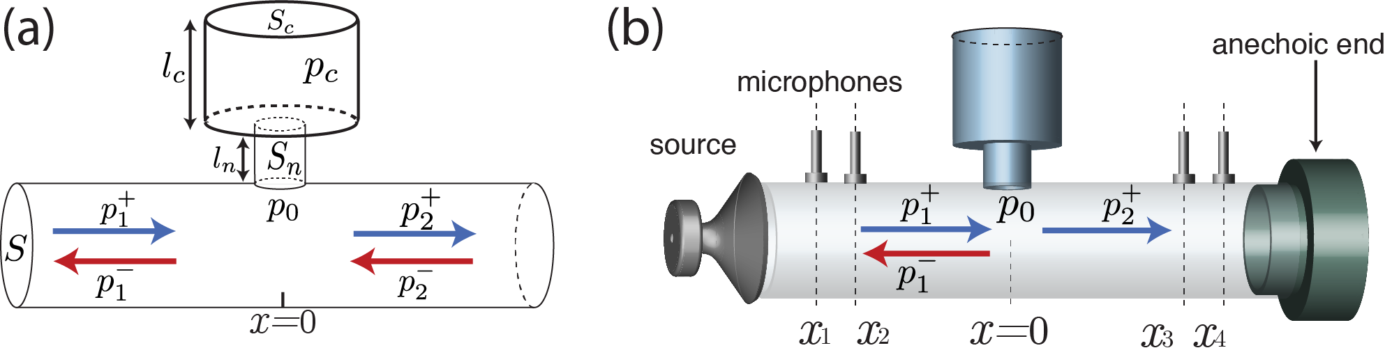
Our system is composed of a HR side-loaded at to a waveguide, see Fig. 1. In this section, we derive simplified equations that describe the dynamics of the system in the general case of two, high pressure incident waves. The HR that we consider is composed by a cylindrical neck, with a cross-section and length , and a cylindrical cavity of cross-section and length . For the low frequency range, the related wavelengths are much larger to the geometric characteristics of the neck, , and of the cavity, . The former leads to the neglection of the compressibility of the fluid in the neck while the later to the assumption that the pressure field inside the cavity is uniformly distributed.
In this case, the dynamics of the pressure in the cavity of the resonator , can be described by the following approximate equation sugi1 ; chinese ; singh1 ; boek :
| (1) |
where () indicates differentiation with respect to time, denotes the pressure at the entrance of the resonator (see Fig. 1), is the resonance frequency of the HR, and is the speed of sound. indicates the corrected neck length Kergomard1 ; Dubos taking into account both the acoustic radiation into the cavity and the waveguide. The resistance factor is a small parameter which quantifies the viscothermal losses in the resonator singh1 ; Melling . The parameter of the nonlinear term in Eq. (1), depicts a characteristic pressure beyond which nonlinear losses become important. It is connected with flow separation and vorticity in the neck and it is approximated by (see sugi1 ; singh1 ; boek ) where is the density of air and is the vena-contracta coefficient having a value of for a neck with hard edges. The nonlinear response of the HR presents different behavior depending on the detailed geometrical characteristics of the edges of the neck Ingard ; Dissel ; yve ; temiz . Different regimes of this behavior can be quantified by the Strouhal number where is the particle velocity in the neck of the resonator. When , particle displacement is smaller than the diameter of the neck and the system is linear. In the opposite, strongly nonlinear limit, and particle velocities are large enough so that vortices are created and are blown away, as a jet, out of the resonator neck. The dynamics, described by Eq. (1), is a good approximation for these limiting cases, and in the strongly nonlinear regime, the term analogous to , quantifies the acoustic energy jetting out of the resonator. On the other hand, for moderate values of and especially for , there is no analytical model to describe the nonlinear behavior of the HR but, for example, correction functions were proposed in Ref. temiz to provide a link between the two limits.
The waveguide, in which the HR is side-loaded, is a cylindrical duct of cross-section . For a frequency range well below the first cut-off frequency of the waveguide, propagation is considered one-dimensional. In addition, for small lengths of the waveguide, to avoid the accumulative nonlinear behavior, it can be considered linear. Thus, the acoustic propagation is described by the following linearized mass and momentum conservation laws:
| (2) |
where and are the pressure and particle velocity in the waveguide. For a HR located at , we can write the acoustic field inside the waveguide as:
| (6) |
where , while + and - denote right- and left-going waves respectively. Considering the HR as a point scatterer, continuity of pressure at yields the relation:
| (7) |
The linearized conservation of mass in the HR cavity is given by
| (8) |
Additionally, using conservation of acoustic flux at in the waveguide, combined with Eqs. (2), (6) and (8) we find the following relation
| (9) |
where the primes denote differentiation with respect to . By integrating Eq. (9) in time, we obtain
| (10) |
where is a coefficient describing the coupling strength between the HR and the waveguide. Finally, using Eqs. (1), (7) and (10), the dynamics of the pressure , inside the HR cavity, is described by the following equation:
| (11) |
The incident waves from the left, , and from the right, , act as drivers. The additional dissipative term proportional to , describes the leakage rate of energy out of the HR (resonator-waveguide coupling). When the “boundary conditions” (i.e. conditions for incident or outgoing waves) are known, the scattering properties of the system are determined by Eqs. (7), (10) and (11). Below we focus on two examples of such conditions i) a case with two-sided incidence and ii) a case of an one-sided incidence combined with an anechoic termination.
II.1 Two-sided incidence and CPA
In the following, we investigate the boundary condition which corresponds to the phenomenon of CPA for monochromatic incoming waves, i.e. , . For the two-sided incident system, CPA boundary condition implies that outgoing waves must vanish, namely . From Eq. (7), this requirement implies which corresponds to a symmetric CPA APL . Moreover, from Eqs. (7) and (10), we obtain that and Eq.(11) can be written as
| (12) |
Note that due to the CPA condition, the coupling term in Eq. (12), appears as an effective gain. Since we are interested in the frequency range close to the resonance, and for sufficiently small pressure amplitudes we consider the nonlinear damping to be of the same order as the linear term . For the HR used in our experiments and for cavity pressures of approximately dB the nonlinear coefficient and the linear damping coefficient are of the same order and take values . Thus, similarly to singh1 , we look for the stationary solution of Eq. (12) applying the Lindstedt-Poincaré perturbation technique Nayfeh up to first order, neglecting the contribution of higher harmonics. The requirement of the annihilation of the secular terms, leads to the conclusion that this particular type of nonlinearity does not introduce a frequency shift, in this order, and imposes the following condition
| (13) |
Thus, CPA occurs at the resonance frequency , under symmetric and in-phase incoming waves, and when the linear and nonlinear decay rates are balanced with the leakage rate . Note that the CPA condition depends on the cross-section of the waveguide, and on the geometry of the HR neck on the cavity. As such, the same condition may apply for different frequencies by tuning the length of the cavity.
II.2 One-sided incidence and critical coupling
Eq. (13) can be seen as an amplitude-dependent extension of the critical coupling condition Haus ; PA1 ; PA2 . It was recently shown that, for the case of an incident wave from the left and an anechoic termination on the right of the waveguide in the linear regime, a critically coupled HR leads to a maximum absorption of Merkel . For the considered setup, we can define the transmittance , reflectance and absorption as
| (14) |
The absorption , when the critical coupling condition Eq. (13) is satisfied, can be calculated from Eqs. (7), (9) and (11), and it is also found to be , for the case of a HR with nonlinear losses.
III Experimental results
We now turn to one-sided incidence experiments to confirm the nonlinear critical coupling. To do so, we measure the absorption for different amplitudes and frequencies of incident waves and verify that nonlinear losses can lead to an absorption of when condition (13) is satisfied.
III.1 Setup
We perform experiments using the apparatus shown in the right panel of Fig. 1. The geometrical characteristics of the setup are: m2, m2, m2, m and m. A compression driver (Beyma CP800TI), tuned to provide high amplitude waves with very low harmonic distortion, connected to a linear amplifier (Devialet D-Premier), is used as a source at one side of the cm long waveguide. An anechoic termination is located at the other side providing reflection below for the considered range of frequencies and amplitudes. Measurements of the pressure are performed at four different positions using a inch B&K free field microphone. Assuming that the propagation is linear in the waveguide, we experimentally determine , and by using the four-microphones method Song ; Muehleisen . This procedure is repeated for several values of the amplitude of the incident wave from approximately dB to dB.
III.2 Nonlinear impedance model
To compare the experimental results with the theory of the previous section, we note that a nonlinear impedance of the resonator can be obtained from Eq. (1), and it can be written as singh1 where , and are the linear reactance, linear resistance and the nonlinear resistance respectively. The linear part of the impedance is found to be while the nonlinear:
| (15) |
We note that the linear part, which is obtained from the simplified model of Eq. (1), is valid for wavelengths sufficiently larger than the geometric characteristics of the neck and of the cavity. The HR used in our experiments is not strictly in this regime. A more accurate expression of the linear HR impedance can be obtained by the transfer matrix method, see appendix of Merkel which predicts a resonance frequency of Hz instead of Hz. The nonlinear resistance in Eq.(15) is linearly dependent on the velocity amplitude, and it is known to be a good approximation in the strongly nonlinear regime () Ingard ; temiz . Nevertheless, as it is mentioned in Section II, the nonlinear response of the resonator highly depends on the detailed geometry of the neck edges, the Strouhal number and other factors such as the shear number. Thus, in order to have a better agreement with the experimental results, we use a nonlinear resistance , where has the following form
| (16) |
while the parameter is a fitting parameter. The function is chosen according to the recent results of Ref. temiz to satisfy the corresponding known limits of linear () and nonlinear () response of the resonator. Using the definitions in Eq. (14) ,we can write the transmittance and reflectance as functions of the impedance
| (17) |
where .
III.3 Results
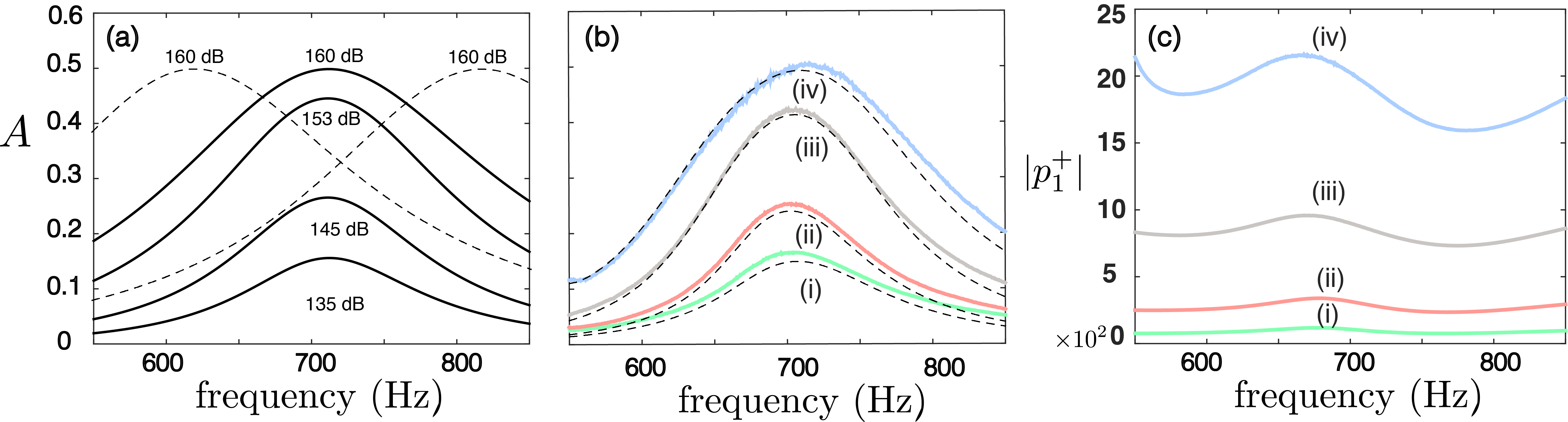
In panel (a) of Fig. 2, we plot the theoretically obtained absorption for different values of the incident amplitude , using the nonlinear impedance model with , for a HR corresponding to our experimental setup. As it is observed, for increasing incident amplitudes the maximum of absorption increases, and reaches the value of for dB at the resonance frequency . The dashed lines correspond to the same amplitude of dB but for different cavity lengths, cm (left shifted line) and cm (right shifted line), verifying that can be reached at the same amplitude, for different frequencies by tuning the length of the cavity. In panel (b) of Fig. 2, the solid lines depict the experimentally obtained absorption with the corresponding experimental incident wave amplitudes shown in panel (c). Note that small variations of the frequency of maximum absorption observed in panel (b), are due to the fact that the incident wave amplitudes are frequency dependent caused by the coupling between the reflected wave and the transducer. The dashed lines in panel (b), show the theoretical prediction as obtained using the nonlinear impedance and the fitting function with , where the velocity of the neck is calculated using the experimental value s of the incident pressure shown in panel (c). The good agreement between theory and experiment demonstrates that the nonlinear response of the HR is adequately described by the nonlinear impedance with the additional fitting.
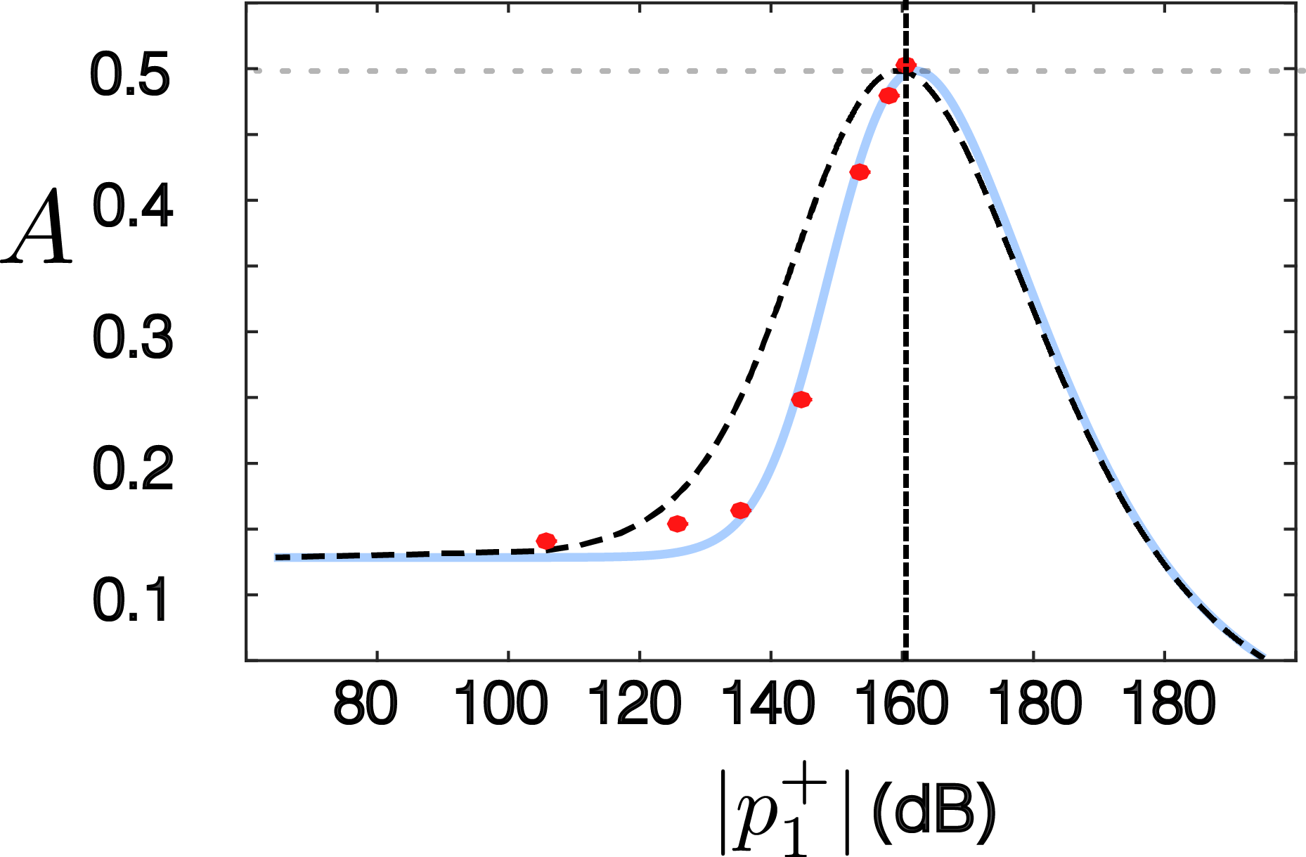
To directly compare the experimental results with the analytical condition for CPA given by Eq. (13), in Fig. 3 we show the absorption for the resonance frequency , as a function of . The (red) dots depict the experimentally obtained values, and is reached for an incident amplitude of dB. More importantly, this is the value predicted by Eq. (13) as indicated by the vertical dashed line, and it verifies that: critical coupling can be induced by nonlinear losses when, in addition with the linear ones, they balance the leakage to the waveguide. The blue solid line is obtained using the theoretical nonlinear HR impedance with , while the dashed line corresponds to the case of and thus to the prediction of the simplified model of Eq. (1). Comparing the two theoretical curves, one observes that indeed at the two limits (linear and strongly nonlinear ), they coincide as expected (see discussion after Eq. 16). However in the intermediate regime (between dB and dB), the impedance with the fitting function describes more accurately the experimental results.
IV Conclusions
In this work we present a simplified model, to study the linear wave propagation in a waveguide, side-loaded with a Helmholtz resonator which exhibits nonlinear losses. Through this model, we extract the suitable conditions depending on the geometrical characteristics and on the amplitude of the incident waves, in order to achieve CPA. These conditions imply that CPA occurs at the resonance of the HR, when the linear and the additive nonlinear losses of the resonator, balance the leakage to the waveguide under symmetric two-sided incidence. For the one-sided incidence case, when the energy leakage criterion is satisfied, the HR is critically coupled giving rise to a maximum of absorption . Extension of this study into more complex configurations could lead to the design of broadband high amplitude acoustic absorbers with applications into aeronautics.
We thank Y. Auregan, V. Pagneux and A. Hirschberg for helpful comments. This work has been funded by the Metaudible project ANR-13-BS09-0003, co-funded by ANR and FRAE.
References
- (1) H. Kuttruff, Room Acoustics, 5th ed. (Elsevier Science Publishers Ltd, London, 2009), pp. 1-349.
- (2) T. J. Cox, P. D’Antonio, Acoustic Absorbers and Diffusers: Theory, Design and Application, 2nd ed. (Taylor & Francis, London, 2004), pp. 1-476.
- (3) M. L. Munjal, Acoustics of ducts and mufflers, 2nd ed. (John Wiley and Sons, New York, 2014), pp. 1-416.
- (4) B. Kotzen and C. English, Environmental Noise Barriers, 2nd ed. (Taylor & Francis, London, 2009), pp. 1-258.
- (5) Hermann A. Haus, Waves and Fields in Optoelectronics, (Prentice Hall, New Jersey, 1984), pp. 197-216.
- (6) Y. Xu, Y. Li, R. K. Lee, and A. Yariv, ”Scattering-theory analysis of waveguide-resonator coupling”, Phys. Rev. E 62, 7389 (2000).
- (7) M. Cai, O. Painter, and K. J. Vahala, ”Observation of critical coupling in a fiber taper to a silica-microsphere whispering-gallery mode system”, Phys. Rev. Lett. 85 (2000).
- (8) V. Romero-Garcia, G. Theocharis, O. Richoux, A. Merkel, V. Tournat, V. Pagneux, ”Perfect and broadband acoustic absorption by critically coupled sub-wavelength resonators”, Sci. Rep. 5, 19519; doi: 10.1038/srep19519 (2015).
- (9) V. Leroy, A. Strybulevych, M. Lanoy, F. Lemoult, A. Tourin, J. H. Page, ”Superabsorption of acoustic waves with bubble metascreens”, Phys. Rev. B 91, 020301 (2015).
- (10) V. Romero-García, G. Theocharis, O. Richoux, V. Pagneux, ”Use of complex frequency plane to design broad and subwavelength absorbers”, J. Acoust. Soc. Am, submitted.
- (11) A. Merkel, G. Theocharis, O. Richoux, V. Romero-Garcia and V. Pagneux, ”Control of acoustic absorption in one-dimensional scattering by resonant scatterers”, Appl. Phys. Lett. 107, 244102 (2015).
- (12) G. Ma, M. Yang, S. Xiao, Z. Yang, and P. Sheng, ”Acoustic metasurface with hybrid resonances”, Nature Mater. 13, 873-878 (2014).
- (13) N. Sugimoto, M. Masuda, and T. Hashiguchi,”Frequency response of nonlinear oscillations of air column in a tube with an array of Helmholtz resonators”, J. Acoust. Soc. Am. 114(4), 1772 (2003).
- (14) G. K., Yu, Y. D. Zhang, and Y. Shen, ”Nonlinear Amplitude-Frequency Response of a Helmholtz Resonator”, J. Sound and Vibration, 133(2), 024502 (2011).
- (15) D. K. Singh, S. W. Rienstra, ”Nonlinear asymptotic impedance model for a Helmholtz resonator liner, J. Sound and Vibration 333 (15), 3536 (2014).
- (16) S.W. Rienstra, A. Hirschberg, An Introduction to Acoustics, Technical Report, Technische Universiteit Eindhoven, Revised and updated version of IWDE 92-06 (2012).
- (17) K. N. Reddy, A. V. Gopal, and S. Dutta Gupta, “Nonlinearity induced critical coupling”’, Optics Lett. 38(14), 2517 (2013).
- (18) T. H. Melling, “The acoustic impedance of perforates at medium and high sound pressure levels”, J. Sound and Vibration, 29(1), 1 (1973).
- (19) J. Kergomard and A. Garcia, ”Simple discontinuities in acoustic waveguides at low frequencies: Critical analysis and formulae”, J. Sound and Vibration114(3), 465 (1987).
- (20) V. Dubos, J. Kergomard, D. Keefe, J.-P. Dalmont, A. Khettabi, and K. Nederveen, ”Theory of Sound Propagation in a Duct with a Branched Tube Using Modal Decomposition”, Acta Acustica united with Acustica85(2), 153 (1999).
- (21) U. Ingard, and H. Ising, ”Acoustic Nonlinearity of an Orifice”, J. Acoust. Soc. Am.42, 6 (1967) .
- (22) J. H. M. Disselhorst, and L. van Wijngaarden, ”Flow in the exit of open pipes during acoustic resonance”, J. Fluids and Structures 90, 293 (1980).
- (23) Y. Auregan and M. Pachebat, ”Measurement of the non-linear behavior of acoustical rigid porous materials”, Physics of Fluids 11, 1342 (1999).
- (24) M. A. Temiz, J. Tournadre, I. L. Arteaga, and A. Hirschberg, ”Non-linear acoustic transfer impedance of micro-perforated plates with circular orifices”, accepted, J. Sound and Vibration; doi:10.1016/j.jsv.2015.12.022 (2015).
- (25) P. Wei, C. Croenne, S. T. Chu, and J. Li, ”Symmetrical and anti-symmetrical coherent perfect absorption for acoustic waves”, Appl. Phys. Lett. 104, 121902 (2014).
- (26) A. H. Nayfeh, Introduction to Perturbation Techniques, (Wiley, New York. 1981), pp. 118-121.
- (27) B. H. Song and J. S. Bolton, ”A transfer-matrix approach for estimating the characteristic impedance and wave numbers of limp and rigid porous materials”, J. Acous. Soc. Am.107, 1131–1152 (2000).
- (28) R. T. Muehleisen and C. W. Beamer IV, ”Comparison of errors in the three- and four-microphone methods used in the measurement of the acoustic properties of porous materials”, ARLO 3(4), 112 (2002).