Functional colloidal micro-sieves assembled and guided above a channel-free magnetic striped film†
Fernando Martinez-Pedrero,a Arthur V. Straube,b Tom H. Johansen,c,d and Pietro Tierno∗a,e
Paper published in Lab on a Chip 15, 1765 (2015). DOI: 10.1039/c5lc00067j
Abstract
Colloidal inclusions in lab-on-a-chip devices can be used to perform analytic operations in a non-invasive fashion. We demonstrate here a novel approach to realize fast and reversible micro-sieving operations by manipulating and transporting colloidal chains via mobile domain walls in a magnetic structured substrate. We show that this technique allows to precisely move and sieve non-magnetic particles, to tweeze microscopic cargos or to mechanically compress highly dense colloidal monolayers.
1 Introduction
††footnotetext: † Electronic Supplementary Information (ESI) – Five movies (.AVI) illustrating the experiments and one file (.pdf) describing details of the theoretical model – is freely available via DOI: 10.1039/c5lc00067j††footnotetext: a Departament de Estructura i Constituents de la Matria, Universitat de Barcelona, Av. Diagonal 647, 08028 Barcelona, Spain. E-mail: ptierno@ub.edu††footnotetext: b Institut für Physik, Humboldt-Universität zu Berlin - Newtonstr. 15, D-12489 Berlin, Germany.††footnotetext: c Department of Physics, The University of Oslo, P.O. Box 1048 Blindern, 0316 Oslo, Norway.††footnotetext: d Institute for Superconducting and Electronic Materials, University of Wollongong, Northfields Avenue, Wollongong, NSW 2522, Australia.††footnotetext: e Institut de Nanocincia i Nanotecnologia IN2UB,Universitat de Barcelona, Barcelona, Spain.Microfluidics, the art of handling nanoliter volume of reagents in lithographically customized channel networks, has direct applications in inorganic 1 and analytical 2 chemistry, biochemistry, 3 and life science. 4, 5 The ability to perform complex operations within a micro-channel often requires the use of “active” components, capable to control and process small volumes of sample. 6, 7 The direct implementation of mechanical units able to stir, 8 pump, 9 or sort 10 streams of fluids in a single chip has been successfully demonstrated, although the efficiency in device performance can be further optimized by combining different strategies. 11, 12 In this context, an alternative approach which recently gained popularity relies on the use of micrometer scale colloidal inclusions, 13 where single particles 14 or small clusters of them 15, 16, 17 can be remotely actuated by an applied field, without direct mechanical contact. Several basic functions can be performed in parallel or in a local fashion, where the actuated particles are used as fluid stirrers, pumps, valves or pistons. 18 Besides their addressability via external fields, another advantage of implementing colloidal inclusions in lab-on-a-chip devices, is that the particles can be used as individual drug delivery vectors once their surface is chemically functionalized. 19 Static or low frequency oscillating magnetic fields are often preferred over other types of actuating forces due to their non-invasive nature, and the fact that biological systems remain practically unaffected. 20
Another important function in microfluidics system and, more in general, in chemical engineering, is particle filtration. In lab-on-a-chip devices this operation can be realized in different ways such as by incorporating solid state membranes, or by creating pores via direct chemical etching or photopolymerization, to cite a few methods. 21, 22, 23, 24, 25 In most of the cases, however, particle sieving has been achieved via static structures, characterized by fixed and immobile reliefs, which could not be externally reconfigured at will in order to stop or release the flow of matter.
Here we show an alternative technique to move, sieve and trap colloidal cargos using reconfigurable colloidal chains. These chains are formed and propelled above a channel-free magnetic platform, allowing for an easy assembly or disassembly by simply varying the applied magnetic field parameters.
2 Materials and Methods
2.1 Colloidal particles
As magnetic colloidal particles we use monodisperse paramagnetic microspheres from Invitrogen (Dynabeads M270), composed of a highly cross-linked polystyrene matrix and evenly doped with nanoscale superparamagnetic grains (Fe2O3 and Fe3O4). These particles are characterized by a radius , a density and a magnetic volume susceptibility . 26
As non-magnetic cargos, we use highly monodisperse micro-particles based on silicon dioxide and having sizes ranging from to , which were purchased from Sigma Aldrich. These particles are diluted in the deionized water and mixed at a proper concentration with the paramagnetic colloidal particles before being deposited above the FGF.
2.2 Magnetic film
As a platform for the particle motion we use a structured magnetic substrate, namely a ferrite garnet film (FGF) of composition Y2.5Bi0.5Fe5-qGaqO12 (). The FGF is grown by dipping liquid phase epitaxy on a gadolinium gallium garnet substrate from melt of the constituent rare earths containing bismuth, iron and gallium, as well as PbO and B2O3.27 After successful growth, the FGF chip is characterized by a regular lattice of parallel ferromagnetic stripe domains with alternating perpendicular magnetization, and a spatial periodicity of in zero applied field. As shown in Fig. 1, separating these domains with opposite magnetization are Bloch walls (BWs), i.e. narrow regions ( width) which generate strong gradients in the surface field. Moreover, their positions can be manipulated by applying moderate magnetic fields. Before the experiments, the FGF film is coated with a positive Photoresist AZ-1512 (Microchem, Newton, MA) which is applied by using spin coating (Spinner Ws-650Sz, Laurell) and photo-crosslinked via UV irradiation (Mask Aligner MJB4, SUSS Microtec). The complete procedure can be found in the Supporting information of another article 28.
2.3 Experimental procedure and system
The magnetic colloidal particles are dispersed in water and are electrostatically stabilized by the negative charges acquired from the dissociation of the surface carboxylic groups (). The original aqueous suspension of the particles ( or, equivalently, ) is diluted with highly deionized water (, MilliQ system) and few droplets are deposited above the FGF.
The motion of particles is recorded by using a CCD camera (Balser Scout scA640-74fc) working at . The camera is mounted on top of a light microscope (Eclipse Ni, Nikon) equipped with a , objective and a TV adapter having a magnification . The optic system allows a total field of view of . The positions of the particles in the plane are obtained from the analysis of .AVI movies recorded via a commercial software (STREAMPIX) and later on analyzed using a MATLAB code based on the Crocker and Grier software 29.
The precessing magnetic field is applied to the FGF by using three custom-made solenoids arranged perpendicular to each other and having the main axes along the directions, see Fig. 1. Two coils are connected to an AC power amplifier (AKIYAMA AMP-1800) which is controlled by a waveform generator (TGA1244, TTI) in order to generate a rotating magnetic field in the plane. The third coil is connected to a DC power supply (TTi El 302) to generate a static field along the direction, .
3 Result and Discussion
3.1 Single particle motion
Our experimental system is illustrated schematically in Fig. 1(a). After being placed on the surface of the FGF chip, the magnetic colloids are attracted by the BWs and become confined in two dimensions due to balance between magnetic attraction and steric repulsion. The periodic arrangement of the BWs in the FGF creates a one-dimensional sinusoidal-like potential along the -direction (see Sec. 1 of the ESI). Particle motion
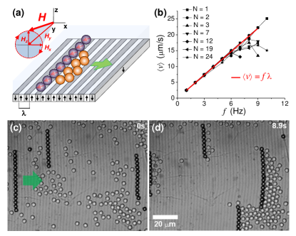
is induced upon application of an external uniform magnetic field rotating in the plane with frequency and amplitude , and with a field ellipticity denoted by ,
| (1) |
The two amplitudes are related to by,
| (2) |
such that and . Unless explicitly stated, we used a circularly polarized magnetic field where and vary the frequencies and the amplitude . For these amplitudes, the applied field modulates the total surface field of the FGF () and generates a traveling wave potential able to transport the particles perpendicular to the stripe pattern as shown in Fig. S1 in the ESI. For low frequencies, the particles follow the magnetic potential, and move at a constant mean speed above the FGF surface. Increasing the driving frequency, the particles reduce their average speed due to the loss of synchronization with the traveling potential. 30, 31
3.2 Magnetic chains and cargo transport
To assemble the moving paramagnetic particles into linear structures, we add to the rotating field a static component of magnitude , which causes the field to perform a conical precession around the -axis, Fig. 1(a). The applied field now reads as, , where continues indicating the amplitude of the rotating field in the plane. For amplitude particles located along the same BW experience attractive dipolar interactions, and rapidly assemble into a one-dimensional chain moving as a compact rod (see Sec. 2 of the ESI for details). For low driving frequency, the average chain speed is constant and proportional to via the relationship , see Fig. 1(b). Under the same field parameters, increasing the chain length decreases the maximum speed achievable due to a corresponding increase in the friction coefficient of the chain.
We used these magnetic chains to transport colloidal cargos with sizes ranging from to to . Indeed, due to the comparable size of magnetic and non-magnetic particles, individual paramagnetic particles are unable to transport microscopic cargos unless the latter are chemically bound to the particle surface. In contrast, chains translating at a prescribed and well controlled speed can be used to translate and accumulate colloidal cargos randomly located above the FGF, as shown in Fig. 1(c,d). Once engaged into directed motion by a propelling chain, the silica particles show negligible thermal fluctuations with a small diffusion coefficient in the transverse () direction, for particles having size. This makes it difficult for them to escape by simply Brownian motion, unless they are located exactly at the edge of the moving chain. Although we demonstrate this concept with colloidal particles, other types of non-magnetic cargos
such as cells, liposomes or emulsion droplets can be equally well propelled.
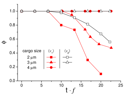
In order to characterize the collection efficiency of our magnetic chains in an open system, we perform a series of experiments by measuring the fraction of non-magnetic cargos which can be transported over a given area by the chain at a constant speed. The area in front of the chain decreases with time as the chain propels. As a consequence, as time proceeds the colloidal cargos start accumulating on one side of the moving chain. The ideal case when all cargos are transported by the moving chain corresponds to . However, the cargos can escape from the moving chain from the top part mainly for two reasons: either due to diffusion in the perpendicular () direction (which takes place only for cargos having very small size), or due to hydrodynamic lift caused by an hydrodynamic perturbation in the solvent generated by a fast translating barrier. Thus in general the quantity . Fig. 2 shows the evolution of versus time for chains propelled by an applied field having amplitudes and and different driving frequencies which correspond to different speeds. The time is normalized by the field frequency as , in order to compare the different experiments done at different frequencies. The tendency of the smaller cargos to cross the moving magnetic chain is reflected by the decreases of starting from for cargos having size and . Particles larger than can be transported along all the area at any density up to their close packing, . For a given size of cargos, reducing the driving frequency increases the collection efficiency since the colloidal cargos have more time to redisperse within the area reduced by the moving chain.
The limitation of our system to collect small particles having size below can become an advantage
for other potential applications. For example, it becomes relevant for sorting bi-disperse particle mixture ( and size), as shown in MoviesS2 in the ESI. With this method, we can capture and transport the larger colloidal cargos, allowing for size separation between fast and slowly diffusing colloidal species deposited over the magnetic film.
3.3 Micro-sieving
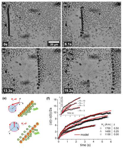
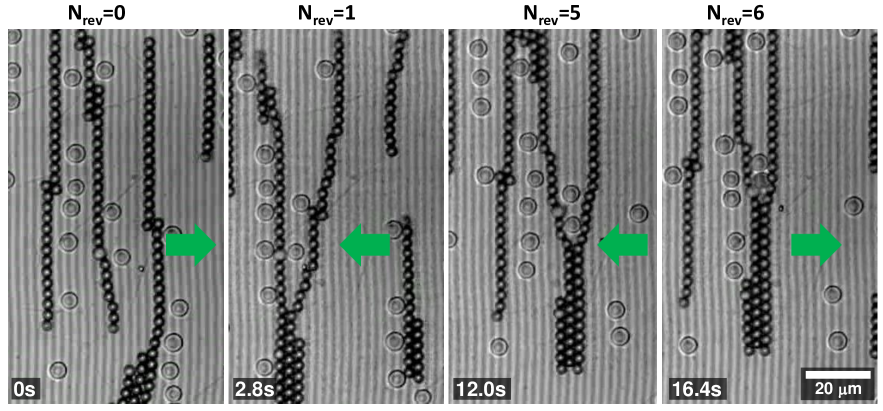
Micro-sieving can be realized by tuning the dipolar interactions which keep the particles in the chain. Fig. 3(a-d) shows a sequence of images where an ensemble of silica particles ( size) are transported by a chain of magnetic particles (chain length ) via a precessing field. After , the -component of the field is switched off, and the chain starts to open up and expand due to repulsive interactions between the magnetic particles. After , the average inter-particle distance, denoted as , exceeds the size of the transported particles, which then start flowing through the orifices driven by the pressure exerted by the moving barrier. At , the expanded chain reaches a length of which corresponds to a mean inter-particle distance of . The flux of silica particles increases by increasing the density of the compressed particles. As shown in MovieS3, the chain can be easily recovered by switching on and the direction of motion reversed by changing the sense of rotation of the field.
The schematics of Fig. 3(e) illustrate the chain expansion mechanism. By switching off , the applied field now rotates in the plane perpendicular to the FGF film, and the magnetic dipoles of the particles forming the chain repel each other since they remain parallel at all times. The transverse kinetics of the chain can be well described by considering the balance between dipolar and friction forces. As derived in Sec. 3 of the ESI, the average end-to-end distance of the chain follows the law:
| (3) |
where the permeability of water is and is a correction factor accounting for the proximity of the FGF surface (see Eq. (10) in the ESI). Since for long chains , being the average inter-particle distance,
we can obtain an estimation of the average sizes of the pores. Fig. 3(f) shows the good agreement between this theoretical prediction and the experimental data for chains driven at different amplitudes of the rotating field . The time in the graph indicates the time when was switched off. The inset shows the results obtained for chains composed of different number of particles. Increasing the amplitude of the rotating field, forces the propelling chain to expand faster, while decreasing the number of particles in the chain increases the expansion process for the same amplitude and frequency of the applied field. In all cases, at longer times, the average distance reaches a plateau where the repulsion reduces significantly. Since we can easily and independently change both and , the chain expansion can be completely controlled by the amplitude of the applied field, allowing only the particles below the pore size to pass through. Note that by setting , the expanding chain can be frozen at any time as soon as it reaches the configuration with a prescribed inter-particle distance.
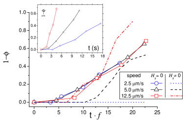
To characterize the efficiency to sieve non-magnetic particles from the expanding pores, we apply the same analysis as in Fig. 2 but now reporting the fraction of silica particles which pass the open chain through the pores created between the magnetic particles when is switched off. Fig. 4 shows this fraction versus the normalized time for three different speeds when compressing size non-magnetic colloids. Together with these data, the corresponding values for moving compact chains in absence of expansion () are shown as dashed and dotted lines. The fact that the scattered points fall all on the same curve rather than disperse, cf. the dotted and dashed lines, shows that the colloidal cargos pass the chain preferentially through the pores rather than circumvent it from the top. The possibility to accurately set the field strength and driving frequency in order to tune the size of the pores between the magnetic particles allows us to speed-up, slow down or even completely stop the sieving process at any time, a feature which is absent in static membranes integrated in microfluidics systems.
3.4 Chain tweezing and compressing operations
Besides sieving operations, a pair of chains can be made attractive until they clamp together performing particle “tweezing”. In particular, the interaction between two moving particles along the direction of motion perpendicular to the stripe pattern can be tuned by varying the ellipticity of the applied field. It was previously shown 32 that when the particles repel each other, while magnetic attraction arises for . We use this feature in Fig. 5 to assemble closely propelling chains into a colloidal ribbon for . The assembly process is induced after moving first forward and later backward the pair of chains, in such a way that the sudden change in the direction of motion causes the deformation of the chains. During this process, one of the particles forming the traveling chain, usually located at one of the two ends, loses the synchronization with the moving magnetic potential. Adjacent particles are forced to follow the retarded colloid, and this delay in the propagation is continuously transmitted along the chain. As a consequence, the lateral distance between the two chains reduces, while the latter approach each other. At a close distance, attractive dipolar interactions assemble the chains into a colloidal ribbon, merging via a zip-like mechanism, and entrapping any particle present between them, as shown in Fig. 5.
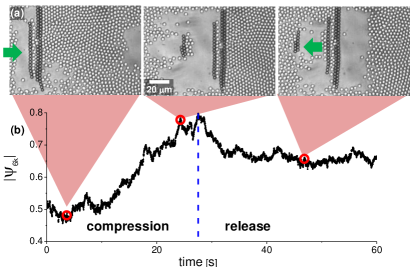
When a pair of chains is stacked into a ribbon, the latter is less prone to be deformed by the colloidal cargo compared to the individual chains. The magnetic ribbon can be thus used as a mobile barrier to compress highly dense monolayer of non-magnetic particles, as shown in Fig. 6(a) and MovieS5. The system turns into an excellent model for studying ordering in two dimensions, where the surface pressure can be simply varied by moving the magnetic barrier along the FGF surface. In order to characterize the solidification (upon compression) and melting (upon release) of the monolayer, we locate the particle positions via tracking routines, and measure the -fold bond-orientational order parameter, given by . 33 Here is the angle formed by a particle at location with its nearest neighbor with respect to a reference direction. For a perfect triangular lattice, . As shown in Fig. 6(b), compression of the silica particles leads to the formation of an ordered aggregate of particles in front of the chain () even in absence of a hard wall confinement. Inverting the direction of rotation of the field, releases the monolayer and the particles start to slowly diffuse towards the empty area. Melting of the lattice here is induced by thermal diffusion, and the orientational order of the lattice starts to slowly decrease.
4 Conclusions
This article introduces a novel technique to remotely manipulate and transport colloidal chains which can be used to perform microscopic sieving and tweezing operations. Permanently linked magnetic chains have been developed by various groups in the past, 34, 35 and used as micromechanical sensors, 36 fluid mixers 37 or stirrers 38, 39 in lab-on-a-chip devices. In all these cases, however, the chains showed a certain degree of flexibility 40 which limited their use in analytic processes. In contrast, in the present case, the magnetic substrate provides the ratchet effect able to drive the particles and, at the same time, strongly pin the chain position reducing its flexibility. One limitation of our system is related to its inherent two-dimensional nature, since the strong confinement of the FGF restricts particle motion to a two-dimensional plane. In order to increase the size of the chain, one could use for example magnetic particles with rectangular shape41. An alternative strategy would be to stack FGFs on top of each other in order to control the particle motion in parallel planes as already proposed by other groups for different systems.42
Also, our approach allows to assemble (and disassemble) magnetic chains via the use of a low-intensity external field, without need of any chemical functionalization in order to link the particles. It should be also emphasized that the FGFs are mechanically robust materials, inert to most chemicals, and transparent to visible light, and can be integrated into any optical microscope system once they are prepared with reduced dimensions (area , thickness ). The FGFs are also compatible with standard soft-lithographic materials like PDMS as shown in the past.43, 44 Finally, the presented technique can be potentially applied to biological systems since, as previously reported,45, 44 the FGF can be used to transport without damaging biological samples, showing thus its promise in becoming a powerful tool for fluid based microscale technology.
5 Acknowledgements
F. M. P. and P. T. and acknowledge support from the ERC starting grant “DynaMO” (No. 335040) and from the MEC via programs No. RYC-2011-07605 and No. FIS2011-15948-E. A.S. and P. T. further acknowledge support from a bilateral German-Spanish program of DAAD (project no. 57049473) via the Bundesministerium für Bildung und Forschung (BMBF).
References
- Abou-Hassan et al. 2010 A. Abou-Hassan, O. Sandre and V. Cabuil, Angew. Chem. Int. Ed., 2010, 49, 6268.
- Kim et al. 1995 E. Kim, Y. Xia and G. M. Whitesides, Nature, 1995, 376, 581.
- Kaigala et al. 2012 G. V. Kaigala, E. Delamarche and R. D. Lovchi, Angew. Chem. Int. Ed., 2012, 51, 11224.
- Cabodi et al. 2005 M. Cabodi, N. W. Choi, J. P. Gleghorn, C. S. D. Lee, L. J. Bonassar and A. D. Stroock, J. Am. Chem. Soc., 2005, 127, 13788.
- Ohno et al. 2008 K. Ohno, K. Tachikawa and A. Manz, Electrophoresis, 2008, 29, 4443–4453.
- Xia and Whitesides 1998 Y. Xia and G. M. Whitesides, Angew. Chem. Int. Ed., 1998, 37, 550.
- Ismagilov 2003 R. F. Ismagilov, Angew. Chem. Int. Ed., 2003, 42, 4130.
- Yuen et al. 2003 P. K. Yuen, G. Li, Y. Bao and U.-R. Müller, Lab. Chip., 2003, 3, 46–50.
- Laser and Santiago 2004 D. J. Laser and J. G. Santiago, J. Micromech. Microeng., 2004, 14, R35–R64.
- Kim et al. 2014 J. Kim, J. Erath, A. Rodriguez and C. Yang, Lab. Chip., 2014, 14, 2480.
- MacDonald et al. 2003 M. P. MacDonald, G. C. Spalding and K. Dholakia, Nature, 2003, 426, 421.
- Psaltis et al. 2006 D. Psaltis, S. R. Quake and C. Yang, Nature, 2006, 442, 381–386.
- Terray et al. 2002 A. Terray, J. Oakey and D. W. M. Marr, Science, 2002, 296, 1841.
- Leach et al. 2006 J. Leach, H. Mushfique, R. Leonardo, M. Padgett and J. Cooper, Lab. Chip., 2006, 6, 735–739.
- Bleil et al. 2006 S. Bleil, D. W. M. Marr and C. Bechinger, Appl. Phys. Lett., 2006, 88, 263515.
- Kavcic et al. 2009 B. Kavcic, D. Babic, N. Osterman, B. Podobnik and I. Poberaj, Appl. Phys. Lett., 2009, 95, 023504.
- Weddemann et al. 2010 A. Weddemann, C. Albon, A. Auge, F. Wittbracht, P. Hedwig, D. Akemeier, K. Rott, D. Meißner, P. Jutzi and A. Hütten, Biosensors and Bioelectronics, 2010, 26, 1152–1163.
- Sawetzki et al. 2008 T. Sawetzki, S. Rahmouni, C. Bechinger and D. M. Marr, Proc. Natl. Acad. Sci. USA, 2008, 105, 20141–20145.
- Mat 2012 Fine Particles in Medicine and Pharmacy, Springer, Ney York, 2012.
- Pamme 2006 N. Pamme, Lab Chip, 2006, 6, 24–38.
- de Jong et al. 2006 J. de Jong, R. G. H. Lammertink and M. Wessling, Lab Chip, 2006, 6, 1125–1139.
- Min et al. 2008 K. S. Min, L. S. Hoon and S. K. Yang, Lab Chip, 2008, 8, 1015 1023.
- Lenshof and Laurell 2010 A. Lenshof and T. Laurell, Chem. Soc. Rev., 2010, 39, 1203 1217.
- Didar and Tabrizian 2010 T. F. Didar and M. Tabrizian, Lab Chip, 2010, 10, 3043 3053.
- Didar et al. 2013 T. F. Didar, K. Li, M. Tabrizian and T. Veres, Lab Chip, 2013, 13, 2615–2622.
- Helseth 2007 L. E. Helseth, J. Phys. D: Appl. Phys., 2007, 40, 3030.
- Tierno et al. 2009 P. Tierno, F. Sagués, T. H. Johansen and T. M. Fischer, Phys. Chem. Chem. Phys., 2009, 11, 9615–9625.
- Tierno 2012 P. Tierno, Soft Matter, 2012, 8, 11443.
- Crocker and Grier 1996 J. C. Crocker and D. G. Grier, J. Colloid Interface Sci., 1996, 179, 298.
- Tierno 2012 P. Tierno, Phys. Rev. Lett., 2012, 109, 198304.
- Straube and Tierno 2013 A. V. Straube and P. Tierno, Europhys. Lett., 2013, 103, 28001.
- Straube and Tierno 2014 A. V. Straube and P. Tierno, Soft Matter, 2014, 10, 3915.
- Helseth et al. 2004 L. E. Helseth, H. Z. Wen, R. W. Hansen, T. H. Johansen, P. Heinig and T. M. Fischer, Langmuir, 2004, 20, 7323–7332.
- Philipyx et al. 1997 J. Philipyx, O. Mondain-Monvalz, F. L. Calderonz and J. Bibette, J. Phys. D: Appl. Phys., 1997, 30, 2798.
- Biswal and Gast 2003 S. L. Biswal and A. P. Gast, Phys. Rev. E, 2003, 68, 021402.
- Goubault et al. 2003 C. Goubault, P. Jop, M. Fermigier, J. Baudry, E. Bertrand and J. Bibette, Phys. Rev. Lett., 2003, 91, 260802.
- Furst et al. 1998 E. M. Furst, C. Suzuki, M. Fermigier and A. P. Gast, Langmuir, 1998, 14, 7334.
- Ranzoni et al. 2010 A. Ranzoni, X. J. A. Janssen, M. Ovsyanko, L. J. van IJzendoorn and M. W. J. Prins, Lab. Chip., 2010, 10, 179–188.
- Weddemann et al. 2011 A. Weddemann, F. Wittbracht, A. Auge and A. Hütten, Microfluid Nanofluid, 2011, 10, 459–463.
- Petousis et al. 2007 I. Petousis, E. Homburg, R. Derks and A. Dietzel, Lab. Chip., 2007, 7, 1746–1751.
- Tavacoli et al. 2013 J. W. Tavacoli, M. Fermigier, D. Bartolo, J. Heuvingh and O. du Roure, Soft Matter, 2013, 9, 9103.
- Chern et al. 2014 G. Chern, C. Reichhardt and C. Nisoli, Appl. Phys. Lett., 2014, 104, 013101.
- Tierno et al. 2007 P. Tierno, S. V. Reddy, J. Yuan, T. H. Johansen and T. M. Fischer, J. Phys. Chem. B, 2007, 111, 13479.
- Issle et al. 2008 J. Issle, M. Pla-Roca, E. Martínez and U. Hartmann, Langmuir, 2008, 24, 888.
- Dhar et al. 2007 P. Dhar, P. Tierno, J. Hare, T. H. Johansen and T. M. Fischer, J. Phys. Chem. B, 2007, 111, 13097.