Dual Position Sensitive MWPC for tracking reaction products at VAMOS++
Abstract
The characteristics and performance of a Dual Position Sensitive Multi-Wire Proportional Counter (DPS-MWPC) used to measure the scattering angle, the interaction position on the target and the velocity of reaction products detected in the VAMOS++ magnetic spectrometer, are reported. The detector consists of a pair of position sensitive low pressure MWPCs and provides both fast timing signals, along with the two-dimensional position coordinates required to define the trajectory of the reaction products. A time-of-flight resolution of ps (FWHM) was measured. The measured resolutions (FWHM) were mrad and m for the scattering angle and the interaction point at the target respectively. The subsequent improvement of the Doppler correction of the energy of the -rays, detected in the -ray tracking array AGATA in coincidence with isotopically identified ions in VAMOS++, is also discussed.
keywords:
Low pressure Multi-Wire Proportional Counter (MWPC), VAMOS++, Tracking of heavy reaction products, Doppler correction, Energies around the Coulomb barrier.PACS:
29.40.Cs , 29.40.Gx , 25.70.z1 Introduction
Nuclear reactions at energies around the Coulomb barrier are a powerful tool to investigate nuclear structure and dynamics. Heavy-ion fusion reactions in conjunction with large -ray detector arrays have been used to understand behaviour of nuclei at the extremes of angular momentum [1]. Isotopically identified fission fragments, from fission induced by heavy-ion fusion or transfer, have been recently used to characterize neutron-rich nuclei at large angular momentum [2, 3] and also to study the multidimensional facets of the fission process [4, 5]. More peripheral collisions, around the Coulomb barrier, have also played a role in understanding the mechanism of nuclear transfer [6] and to populate nuclei far away from stability [7, 8]. Direct reactions, in particular using radioactive ion beams, are a powerful tool to probe nuclear shell-evolution [9, 10].
At beam energies around the Coulomb barrier, the isotopic identification (mass () and atomic () numbers) of the various reaction products is challenging for medium mass and heavy nuclei. This is especially required when the nuclei of interest are produced with small production cross-sections among a large number of different reaction products. Isotopic identification can be efficiently achieved using a large acceptance spectrometer combined with suitable detection system. In the last decade, several large acceptance spectrometers like VAMOS++ [11, 12], PRISMA [13] and MAGNEX [14, 15] were built. The performance of such a spectrometer depends on the ion trajectory reconstruction method and can be further improved with the knowledge of the interaction position on the target. The direct measurement at the entrance of the spectrometer of the scattering angles and the interaction point on the target will result in less stringent conditions on optical properties of the beam.
The PRISMA and VAMOS++ spectrometers have been coupled with a large -ray detector array like CLARA [16] and EXOGAM [17] respectively for probing spectroscopy of neutron-rich nuclei [7, 18, 19, 20]. The advent of new generation of -ray tracking arrays AGATA [21] and GRETINA [22] led to an improved determination of the first interaction point in the detector and also allowed to increase their operating rate with larger -ray multiplicities. The increased granularity results in an improved Doppler correction of -rays emitted in flight, provided that the velocity vector of the recoiling ion is measured with sufficient precision on an event-by-event basis. Typically, resolutions, in scattering angle of the ion and definition of the interaction point at the target, better than and 1 mm respectively are required so that the final Doppler corrected -ray energy resolution is limited only by pulse shape analysis and -ray tracking capabilities.
For measuring the velocity vector at PRISMA, a single Micro-Channel-Plate detector placed at the entrance of the spectrometer [23], provided the two-dimensional position and a timing signal for the reaction products, assuming a point like beam spot on the target. A large area MWPC located in the focal plane provided the two-dimensional position and timing signal for the time-of-flight measurement [13]. At VAMOS++, start and stop detectors were used, at the entrance and focal plane of the spectrometer [12]. The scattering angles at the target were obtained from a reconstruction method which used the trajectory of the ions measured at the focal plane by drift chambers [12, 11]. The resulting angular resolution was sufficient for the Doppler correction given the relatively large angular opening of the electrical segmentation of the EXOGAM clover detectors [17]. However, it is insufficient for the superior angular resolution of the AGATA -ray tracking array.
With the above motivations, a new Dual Position Sensitive Multi-Wire Proportional Counter (DPS-MWPC), providing time information, a measurement of the scattering angle and interaction point on the target, was developed. Here the characteristics and performance of this new detector are reported.
2 Detector description
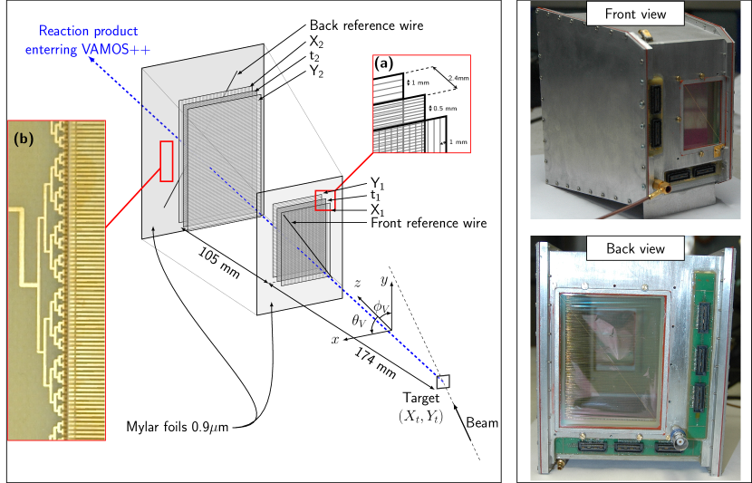
The purpose of the present detector is to detect low energy ions produced in reactions at energies around the Coulomb barrier in the vicinity of magnetic fringe fields and close to target bombarded with intense heavy ion beams. Hence, low pressure Multi-Wire Proportional Counters (MWPC) [24, 25, 26] were chosen. The new detector assembly consists of a pair of two dimensional position sensitive MWPC in a common gas volume placed between the reaction target and the entrance of the VAMOS++ spectrometer. A schematic view of the detector assembly is shown in Fig. 1. The front and back MWPC have active areas of mm2 and mm2 respectively. Each detector is composed of three electrodes: a central cathode that provides a time signal () and two orthogonally oriented anodes wire planes (,) (Fig. 1(a)). The cathodes of the two MWPCs are separated by 105 mm, and the detector assembly is placed 174 mm downstream of the target. Such a geometry allows the detector to cover the full angular acceptance of the VAMOS++ spectrometer ( and in the horizontal and vertical direction respectively). For each of the MWPC, the cathode is composed of gold plated tungsten wires with a diameter of 20 m and separated by 0.5 mm. The and anodes are composed of 20 m gold plated tungsten wires separated by 1.0 mm. The cathode and anode planes are separated by a gap of 2.4 mm (Fig. 1(a)). The different spacing between the wires for the cathode and the anodes was chosen to obtain the required avalanche amplification gain. To avoid a dispersion in the measurement of the time signal due to the propagation of the signal along the different wires, equivalent path lengths of the cathode signal were designed so that it is independent of the position. This is illustrated in Fig. 1(b) for one of the time planes used in the MWPC. The residual time dispersion, arising due to the varying position, can be corrected on through software on an event-by-event basis. Entrance and exit Mylar windows with 0.9 m thickness isolate the gas volume. Two gold plated tungsten wires (100 m diameter) are placed diagonally 1 cm up and downstream of the front and back MWPC respectively. These reference wires are used to align the detector assembly and obtain the position resolution (see Section 3.2). The detector system is operated using isobutane (C4H10), with gas pressure ranging between 2 and 6 mbar. Voltages on the cathode are chosen to optimize the amplitude of the signal (depending on the dynamic ranges for the energy loss and velocity of the detected ions). Typical values ranging between V and V, were used. Permanent magnets, placed outside the reaction chamber, were sufficient to suppress the remaining effect of -electrons originating from the atomic interaction of the heavy-ions with the target.
The MWPC timing signals were amplified by ORTEC FTA820 fast timing amplifiers. The amplified signals were sent to an Enertec 7174 Constant Fraction Discriminator (CFD) using 20% of the original signal, that provided the start signals for the time-of-flight measurements. The stop signal, generated using an analogous electronic chain, was provided by a large area MWPC located in the focal plane of VAMOS++ [12]. The time-of-flight was measured using an ORTEC 566 Time to Amplitude Converter (TAC). The charge collected on each wire was individually integrated and multiplexed using GAS SIlicium multiPLEXing chips (GASSIPLEX) [27]. The readout was ensured by CAEN V551 sequencer and CAEN Readout for Analog Multiplexed Signals (C-RAMS) V550 modules.
The DPS-MWPC at VAMOS++ has the following advantages:
-
1.
Direct and precise two-dimensional measurements of the position of reaction products provide the scattering angle and the interaction point on the target. This also allows the control of the shape and position of the beam spot. The twofold measurement also allows to increase the detection efficiency [28].
-
2.
A pair of fast timing signals are available for the start of the time-of-flight measurements.
-
3.
Individual readout of charges collected on the wire planes allows a uniform signal to noise ratio over the complete detector size as compared to the use of delay lines [13, 28, 29]. Further, the direct measurement of the charge distribution allows a multi-track detection capability [26] and thus the treatment of pile-up events.
-
4.
The use of a common volume of gas, at low gas pressure (2-6 mbar), with thin Mylar windows (0.9m), results in a relatively small energy loss and angular straggling that has a minimum impact on the performance of the magnetic spectrometer and focal plane detection system.
-
5.
A limited sensitivity to the magnetic fringe fields (from large aperture quadrupoles) allows an operation without the constraints of magnetic shielding.
-
6.
A limited sensitivity to -electrons produced in the interaction of heavy ion beams with the target allows an operation at higher beam intensities in the absence of electrostatic mirrors.
3 Detector performance
In this section, the performance of the DPS-MWPC assembly, based on source and in-beam measurements made at GANIL, is presented. The time-of-flight, position and angular resolutions of the new detector reported in this section are summarized in Tab. 1.
3.1 Measurements
Two independent measurements were performed to quantify the position and timing performances of the detector. (a) Measurements were made using a collimated 252Cf fission source placed 10 cm in front of the detector assembly. For these measurements an additional MWPC was placed 2 cm in front of the DPS-MWPC and a silicon detector was placed 4 cm behind. The detector was operated at mbar and a cathode voltage of V. (b) An in-beam measurement was also made using 238U beam at 6.2 MeV/u ( pnA) impinging on a 1.85 mg/cm2 thick 9Be target. The fragments from fusion- and transfer- induced fission were isotopically identified in VAMOS++ placed at . The detector was operated at mbar of isobutane, and V was applied on the cathodes.
3.2 Position resolution
For each MWPC, an event is characterized by a timing signal and a charge distribution in the and wire planes. Charge distributions with a typical wire multiplicity of five were observed. The gain matched charge distributions, with a wire multiplicity of at least three, were used to extract the position. A hyperbolic secant function [30] was fitted to the measured charge distributions to obtain the positions (,), (,) for the front and back MWPC respectively.
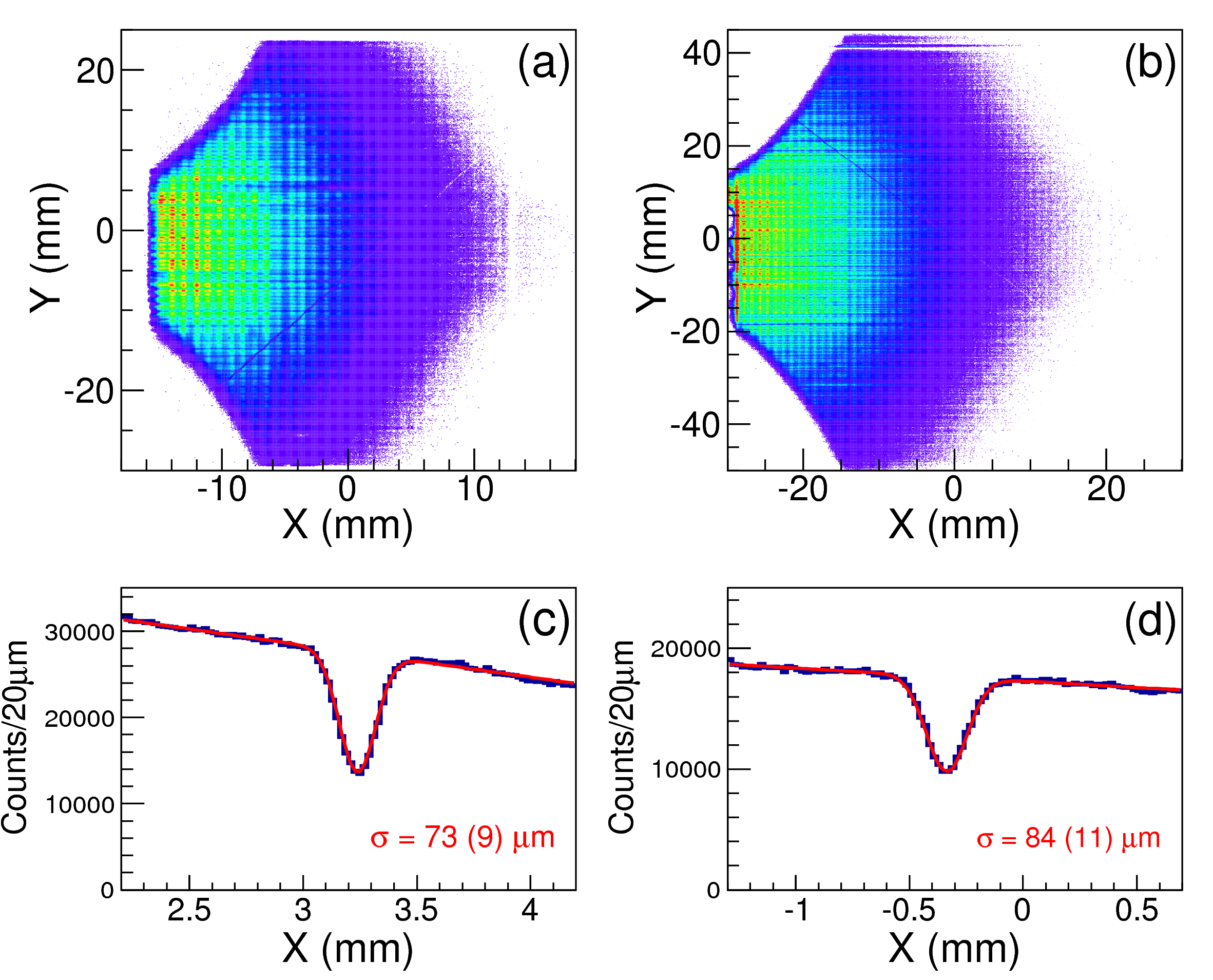
The measurements presented in this section were obtained from the in-beam experiment. The detector was operated in coincidence with ions detected in VAMOS++. The four coordinates (,,,) were used to reconstruct the scattering angles (,) of the detected ion (see Fig. 1). Using these coordinates, the projected position (,) of the ion trajectory on any required plane, and in particular at the target position, could be obtained. Figure 2(a) and (b) show these projections on the plane of the front and back reference wires. The envelope of the distribution of events can be seen to trace the angular acceptance of the spectrometer [11]. The intensity distribution is related to the kinematics of fission (induced by heavy-ion beam in inverse kinematics). The shadows of the reference wires (100 m diameter) can also be seen. The reduction in the number of events at regular intervals (0.5 mm and 1.0 mm along Y and X axis respectively) can be seen in Fig. 2. This arises from the shadowing by the cathode and anode wires. The two-dimensional spectra shown in Fig. 2(a) and (b) can be projected on a plane perpendicular to the corresponding reference wires. Figures 2(c) and (d) show these projections for the front and back reference wires respectively. The profile of the shadow of the wire is used to measure the position resolution of the detector. The above projected spectra were fitted using a function that is a convolution of a slit and a Gaussian function. This describes the shadowing of a wire with given diameter superimposed on linear distribution as a function of position and has the following form:
where: is the convolution of a step and a Gaussian function, is the standard deviation describing the position resolution, is the wire diameter, and parameters are used to locally reproduce the linear behaviour as function of . Using a fixed diameter of the wire (m), an optimization of the measured projection using this function results in resolutions of m and m for the front and back reference wire, respectively. The error on the resolutions arises mainly from the wire deformation (m and m for the front and back MWPC respectively). This was estimated by using the projection for various sub-parts of the reference wire. Additional contributions arise from the uncertainties on the diameter of the wires (m), the position of the projection plane (m) and of statistical nature (m). As the projection involves all the (,,,) coordinates, the quoted resolution can be considered as an upper limit of the intrinsic resolution for a single detector.
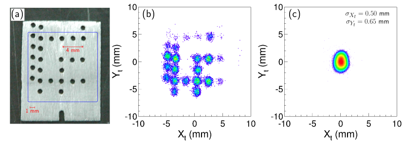
The resulting angular resolution of the scattering angles (,) and position resolution of the interaction point on the target (,) were also investigated. A 1 mm thick aluminum mask, with 1 mm diameter holes, was placed in front of the target (shown in Fig. 3(a)). Figure 3(b) shows the corresponding reconstructed position using the detected fragment. To evaluate the resolution of the projected position and scattering angles, a Monte Carlo simulation for scattered ions, emitted from a 1 mm diameter hole at the target position, was performed. The measured position resolutions included in the simulation reproduced the measured reconstructed image at the target position (Fig. 3(b)). A resulting angular resolution (FWHM) for and was evaluated to be mrad (). Similarly, the position resolution (FWHM) of the interaction point on the target was evaluated to be m. Figure 3(c) shows the profile of the 238U beam measured with the DPS-MWPC, illustrating the tracking capabilities of the detector.
3.3 Time resolution
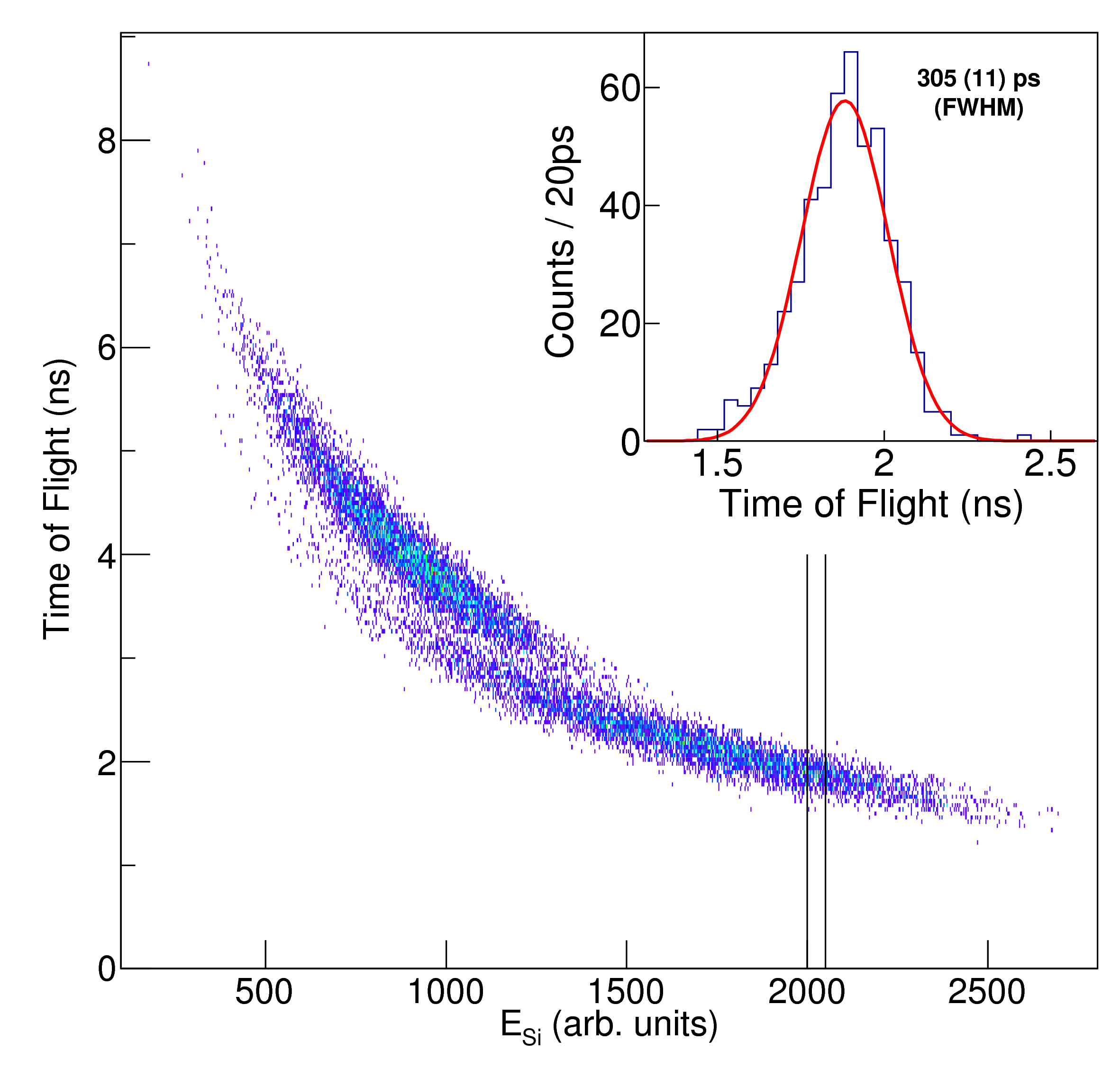
The time-of-flight resolution of the MWPCs was determined using the 252Cf source. The time-of-flight was measured between the additional MWPC and the front MWPC. The residual energy (ESi) was measured in the silicon detector. The two-dimensional spectra shown in Fig. 4 illustrates the correlation between the time-of-flight and the energy. As can be seen in the figure, the light and heavy fission fragments are well separated. The resolution (FWHM) for the time-of-flight, obtained using an energy selection (illustrated in Fig. 4) on a fraction of the light fission fragments, was measured to be ps. Assuming that the start and stop detector have similar time resolutions, the intrinsic time resolution (FWHM) is estimated to be ps.
3.4 Efficiency
The transparency of each MWPC was estimated to be 96% considering the loss of ions due to the stopping by the 20 m wires of the cathode and anode planes. The detection efficiency was obtained from the in-beam measurement for heavy ions with and energies ranging between 2 to 8 MeV/u. The trigger of the acquisition was obtained from VAMOS++ detecting a fission product. Using the correlation of the relevant signals from VAMOS++ and the timing signal and positions (,) from the DPS-MWPC detector, an efficiency % of the reconstructed parameters (, , ) for each MWPC plane was obtained. The efficiency for reconstructing an event (, , , , ) was measured to be %.
| Quantity | Description | Unit | |
|---|---|---|---|
| Time-of-flight | ps | ||
| , | Front MWPC | m | |
| , | Back MWPC | m | |
| , | Scattering angles | mrad | |
| , | Interaction position | m | |
| on the target |
3.5 Doppler correction of -ray energies
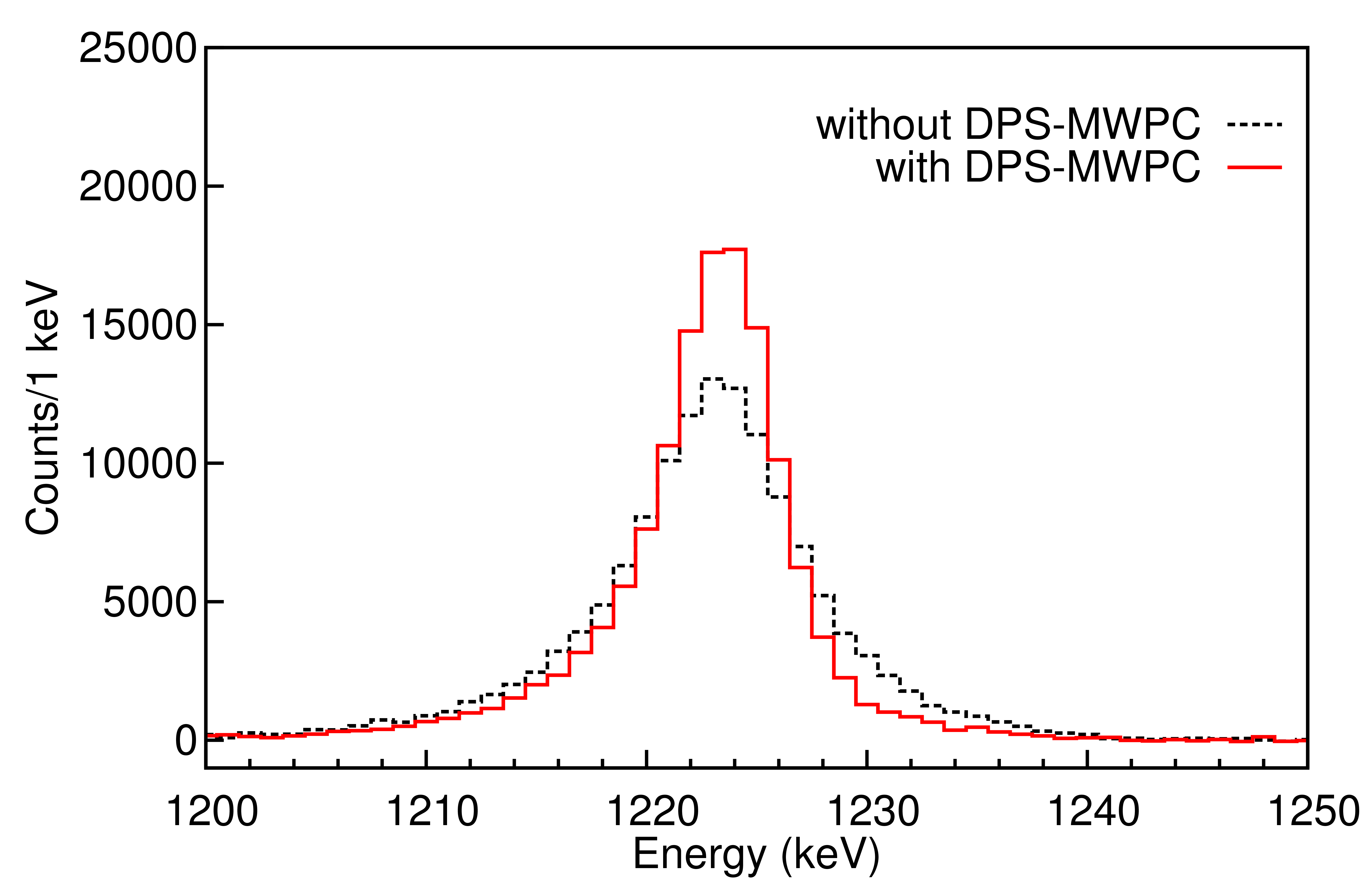
The performance of the event-by-event Doppler correction of -ray energies using the new DPS-MWPC detector is now discussed. Fission fragments from fusion- and transfer-fission produced in the collision of the 238U beam with the 9Be target were detected and isotopically identified in VAMOS++ spectrometer, (see Sect.3.1). Their velocity vectors were measured using the DPS-MWPC detector as described in Sect. 3. The AGATA [21] detectors covered angles from 100∘ to 170∘. The AGATA array was in a compact configuration (translated by 8.8 cm downstream compared to the nominal configuration, where the detectors are at a distance of 23.5 cm from the target). The -ray emission angle was determined using its first interaction point, obtained from pulse shape analysis and tracking procedures [21]. A typical position resolution of 5 mm (FWHM) [31, 32, 33] has been reported for -ray energies around 1.3 MeV. This corresponds to an angular uncertainty of in a compact configuration. Figure 5 shows part of the Doppler corrected -ray spectra including the known 1222.9 (1) keV transition measured using AGATA, in coincidence with 98Zr fragment isotopically identified in VAMOS++. The solid line corresponds to an event-by-event Doppler correction using the measured velocity vector of the scattered ion, the derived interaction point on the target and the first interaction point of the -ray in AGATA. The dashed line spectra corresponds to the Doppler correction where the DPS-MWPC is not used and the scattering angles were derived using an ion trajectory reconstruction method [12, 11, 34]. The improved resolution resulting from the direct measurement of scattering angle and the derived position of the reaction point at the target is evident from the figure. The resolution is improved by a factor of (5.5 (1) keV compared to 8.6 (1) keV). It should be noted that in the nominal configuration, where the detectors are placed at cm from target, a smaller angular uncertainty of will lead to a superior Doppler correction. The excellent performances of the DPS-MWPC reported here, with a typical angular resolution of (FWHM) and the resolution of the derived position of interaction at the target of m (FWHM), are approximately one order of magnitude better than that required for AGATA and hence is compatible with future improvements in the -ray tracking performances.
4 Summary and perspectives
The characteristics and performance of a new dual position sensitive MWPC detector system are reported. This detector is used at the entrance of the VAMOS++ spectrometer and provides both fast timing signals and two-dimensional position coordinates. These define the trajectory of the reaction products, namely the scattering angle and interaction point on the target. A time-of-flight resolution of ps (FWHM) and a position resolution of m (FWHM) have been measured. Angular resolution of mrad and resolution of the interaction point at the target of m were obtained. An overall efficiency of was measured for fission fragments over a wide range of velocities. The above tracking performances were applied to the Doppler correction of -ray energies with the -ray tracking array AGATA. The resolution in the Doppler corrected -ray energy at MeV is improved by a factor of compared to the result obtained using the previous ion trajectory reconstruction method. The angular resolution of the DPS-MWPC is approximately one order of magnitude better than what is required today for a -ray tracking array. It can thus cope with the improvements in the angular resolution of the -ray detection systems.
The DPS-MWPC was routinely used for beam tuning and to optimize the spectrometer performance during the first campaign of AGATA at VAMOS++ in 2015. In the compact configuration of the AGATA, the event-by-event measurement of the interaction point on the target is important to ensure the stability of the beam spot size and position throughout the experiment. For experiments employing direct reactions relying on the kinematical energy-angular correlations [9, 5], the precise determination of the interaction point at the target is essential.
Presently, the performances of the large acceptance spectrometer VAMOS++ rely on an ion trajectory reconstruction method. In such an approach, the measurement of ion trajectories at the focal plane is used to derive the magnetic rigidity, path length in the spectrometer, and the scattering angles at the target, assuming a point like beam spot. It has been shown in the present work that the new detector leads to a large improvement in the determination of scattering angles. This precise determination of the scattering angles and of the interaction point on the target, obtained independently of the spectrometer, coupled to the information from VAMOS++ will result in further improvements of the resolution in the magnetic rigidity and path length and thus provide an improved mass resolution.
Tracking and timing information at the focal plane of VAMOS++ is presently provided by two drift chambers and one large area MWPC respectively. The detector reported in this paper represents a first step towards an implementation of large area dual position sensitive MWPC for both tracking and timing at the focal plane of VAMOS that will result in lower energy losses and improved counting rate capabilities.
Acknowledgements
We would like to thank the AGATA collaboration for the availability of the AGATA -ray tracking array at GANIL. We also thank G. Duchêne and the E680 collaboration for providing the relevant raw data for Fig. 5. We acknowledge the important technical contributions of L. Ménager, J. Ropert and the GANIL accelerator staff.
References
- [1] X. Wang, et al., Evolution of nuclear structure in erbium-158, in: McGRAW-HILL Yearbook of Science and Technology, 2013, p. 119. doi:10.1036/1097-8542.YB130211.
- [2] A. Navin, et al., Phys. Lett. B 728 (2014) 136–140. doi:10.1016/j.physletb.2013.11.024.
- [3] A. Navin, M. Rejmund, Gamma-ray spectroscopy of neutron-rich fission fragments, in: McGRAW-HILL Yearbook of Science and Technology, 2014, p. 137. doi:10.1036/1097-8542.YB140316.
- [4] M. Caamaño, et al., Phys. Rev. C 88 (2) (2013) 024605. doi:10.1103/PhysRevC.88.024605.
- [5] M. Caamaño, et al., Phys. Rev. C 92 (3) (2015) 034606. doi:10.1103/PhysRevC.92.034606.
- [6] L. Corradi, G. Pollarolo, S. Szilner, J. Phys. G Nucl. Part. Phys. 36 (11) (2009) 113101. doi:10.1088/0954-3899/36/11/113101.
- [7] S. Bhattacharyya, et al., Phys. Rev. Lett. 101 (3) (2008) 032501. doi:10.1103/PhysRevLett.101.032501.
- [8] Y. X. Watanabe, et al., Phys. Rev. Lett. 115 (17) (2015) 172503. doi:10.1103/PhysRevLett.115.172503.
- [9] W. N. Catford, et al., Phys. Rev. Lett. 104 (19) (2010) 192501. doi:10.1103/PhysRevLett.104.192501.
- [10] B. Fernández-Domínguez, et al., Phys. Rev. C 84 (1) (2011) 011301. doi:10.1103/PhysRevC.84.011301.
- [11] S. Pullanhiotan, et al., Nucl. Instr. and Meth. A 593 (3) (2008) 343 – 352. doi:10.1016/j.nimA.2008.05.003.
- [12] M. Rejmund, et al., Nucl. Instr. and Meth. A 646 (1) (2011) 184 – 191. doi:10.1016/j.nimA.2011.05.007.
- [13] S. Beghini, et al., Nucl. Instr. Meth. A 551 (2-3) (2005) 364–374. doi:10.1016/j.nimA.2005.06.058.
- [14] A. Cunsolo, et al., Nucl. Instr. and Meth. A 481 (1–3) (2002) 48 – 56. doi:10.1016/S0168-9002(01)01357-2.
- [15] A. Cunsolo, et al., Nucl. Instr. and Meth. A 495 (3) (2002) 216 – 231. doi:10.1016/S0168-9002(02)01610-8.
- [16] A. Gadea, et al., Eur. Phys. J. A 20 (1) (2003) 193–197. doi:10.1140/epja/i2002-10352-9.
- [17] J. Simpson, et al., Acta Phys. Hung. New Seri. Heavy Ion Phys. 11 (2000) 159 – 188. doi:1219-7580.
- [18] J. J. Valiente-Dobón, et al., Phys. Rev. Lett. 102 (24) (2009) 242502. doi:10.1103/PhysRevLett.102.242502.
- [19] J. Ljungvall, et al., Phys. Rev. C 81 (6) (2010) 061301. doi:10.1103/PhysRevC.81.061301.
- [20] D. Montanari, et al., Phys. Lett. B 697 (4) (2011) 288–293. doi:10.1016/j.physletb.2011.01.046.
- [21] S. Akkoyun, et al., Nucl. Instr. and Meth. A 668 (2012) 26–58. doi:10.1016/j.nimA.2011.11.081.
- [22] S. Paschalis, et al., Nucl. Instr. Meth. A 709 (2013) 44–55. doi:10.1016/j.nimA.2013.01.009.
- [23] G. Montagnoli, et al., Nucl. Instr. Meth. A 547 (2-3) (2005) 455–463. doi:10.1016/j.nimA.2005.03.158.
- [24] A. Breskin, et al., Nucl. Instr. and Meth. 143 (1) (1977) 29–39. doi:10.1016/0029-554X(77)90327-5.
- [25] A. Breskin, R. Chechik, N. Zwang, Nucl. Instr. and Meth. 165 (1) (1979) 125–127. doi:10.1016/0029-554X(79)90316-1.
- [26] A. Breskin, Nucl. Instr. and Meth. 196 (1) (1982) 11–21. doi:10.1016/0029-554X(82)90609-7.
- [27] J. C. Santiard, et al., CERN-ECP (1994) 94–17.
- [28] H. Kumagai, et al., Nucl. Instr. and Meth. B 317 (2013) 717–727. doi:10.1016/j.nimb.2013.08.050.
- [29] A. Jhingan, et al., Nucl. Instr. and Meth. A 745 (0) (2014) 106 – 113. doi:10.1016/j.nimA.2013.12.039.
- [30] K. Lau, J. Pyrlik, Nucl. Instr. and Meth. A 366 (2-3) (1995) 298–309. doi:10.1016/0168-9002(95)00604-4.
- [31] F. Recchia, In-beam test and imaging capabilities of the AGATA prototype detector, Ph.D. thesis, Universita degli Studi di Padova (2008).
- [32] F. Recchia, et al., Nucl. Instr. and Meth. A 604 (3) (2009) 555–562. doi:10.1016/j.nimA.2009.02.042.
- [33] P.-A. Söderström, et al., Nucl. Instr. and Meth. A (2011) 1–14doi:10.1016/j.nimA.2011.02.089.
- [34] S. Pullanhiotan, et al., Nucl. Instr. Meth. B 266 (19-20) (2008) 4148–4152. doi:10.1016/j.nimb.2008.05.024.