Single- and double-slit collimating effects on fast-atom diffraction spectra.
Abstract
Diffraction patterns produced by fast He atoms grazingly impinging on a LiF(001) surface are investigated focusing on the influence of the beam collimation. Single- and double- slit collimating devices situated in front of the beam source are considered. To describe the scattering process we use the Surface Initial Value Representation (SIVR) approximation, which is a semi-quantum approach that incorporates a realistic description of the initial wave packet in terms of the collimating parameters. Our initial wave-packet model is based on the Van Cittert-Zernike theorem. For a single- slit collimation the width of the collimating aperture controls the shape of the azimuthal angle distribution, making different interference mechanisms visible, while the length of the slit affects the polar angle distribution. Additionally, we found that by means of a double-slit collimation it might be possible to obtain a wide polar angle distribution, which is associated with a large spread of the initial momentum perpendicular to the surface, derived from the uncertainty principle. It might be used as a simple way to probe the surface potential for different normal distances.
pacs:
34.35.+a,79.20.Rf, 37.25.+kI Introduction
In the last time grazing-incidence fast atom diffraction (GIFAD or FAD) Schuller07 ; Rousseau07 has emerged as a powerful surface analysis technique that allows one to inspect ordered surfaces, providing detailed information on their morphological and electronic characteristics Winter11 ; Debiossac14 ; Zugarramurdi15 . The extreme sensitivity of FAD patterns to the projectile-surface interaction relies on the preservation of quantum coherence Aigner08 ; Lienemann11 ; Bundaleski11 ; Rubiano14 , and in this aspect the collimating conditions of the incident beam play an important role. In particular, recent experimental Winter15 and theoretical Gravielle15 works have shown that FAD patterns are strongly affected by the width of the collimating aperture, which determines that two different mechanisms - Bragg diffraction or supernumerary rainbows - can be alternatively observed.
In this article we theoretically investigate the influence of beam collimation on FAD spectra by considering not only a single-slit but also a double-slit collimating device. In the model, the transversal coherence size of the initial wave packet associated with the incident particle is determined from the collimating conditions by means of the Van Cittert-Zernike theorem BornWolf , while the elastic atom-surface scattering is described within a recently developed semi-quantum approach, named Surface-Initial Value Representation (SIVR) approximation Gravielle14 . The SIVR method offers a clear representation of the main mechanisms of the process in terms of classical trajectories through the Feynman path integral formulation of quantum mechanics Miller01 . It includes an approximate description of classically forbidden transitions on the dark side of the rainbow angle, giving a successful representation of the experimental FAD patterns over the whole angular range Gravielle14 ; Gravielle15 , without requiring the use of convolutions to smooth the theoretical curves Rubiano13 .
The SIVR approximation is here applied to evaluate FAD patterns for He atoms grazingly impinging on a LiF(001) surface after going through a collimating aperture formed by one or two parallel slits. The size and separation of such slits, which limit the effective size of the extended incoherent beam source, determine the aspect of FAD patterns, making different interference mechanisms visible. The paper is organized as follows. The theoretical formalism is summarized in Sec. II. Results for different sizes of the collimating apertures are presented and discussed in Sec. III, while in Sec. IV we outline our conclusions. Atomic units (a.u.) are used unless otherwise stated.
II Theoretical model
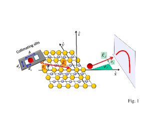
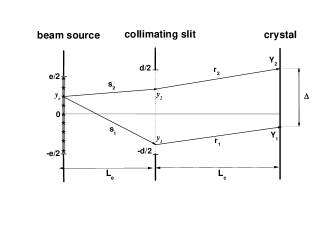
We consider an atomic projectile (), with initial momentum , which is elastically scattered from a crystal surface (), ending in a final state with momentum and total energy , being the projectile mass. The frame of reference is located on the first atomic layer, with the surface contained in the plane, the versor along the incidence direction and the versor oriented perpendicular to the surface, aiming towards the vacuum region (see Fig. 1).
Within the SIVR approximation Gravielle14 , the amplitude per unit of surface area for the transition reads
| (1) | |||||
where is the partial transition amplitude associated with the classical projectile path , with and being the starting position and momentum, respectively, at the time . The functions and describe the profiles of the position and momentum distributions of the initial wave packet, which depend on the beam collimation.
In Eq. (1) the starting position can be expressed as , where is the component parallel to the surface plane and is a fixed distance, here chosen as equal to the lattice constant, for which the projectile is hardly affected by the surface interaction. The partial transition amplitude reads
| (2) | |||||
where represents the surface-projectile interaction, is the projectile momentum transfer, and
| (3) |
is the SIVR phase at the time , with the classical projectile momentum. In Eq. (2) the Maslov function Guantes04
| (4) |
is a Jacobian factor (a determinant) evaluated along the classical trajectory , with the modulus of and an integer number that accounts for the sign of at a given time , satisfying that every time that changes its sign along the trajectory, increases by .
In this work we consider a collimating device formed by equivalent rectangular apertures (with or ) placed in front of an extended incoherent beam source. Each of the rectangular openings is oriented in such a way that the corresponding transversal width, , is parallel to the surface (i.e. parallel to the versor), while the side of length forms an angle with the surface (i.e. with the versor), with being the glancing incidence angle, as depicted in Fig. 1. We assume that the spatial profile of the coherent initial wave packet at a distance from the surface is determined by the complex degree of coherence BornWolf ; Schaff14 . Extending the Van Cittert-Zernike theorem BornWolf to deal with an atomic beam passing through the collimating opening, can be expressed as
where , represents the number of collimating slits, is the collimator-surface distance, is the distance between the centers of the slits, and is the spherical Bessel function. The de Broglie wavelengths and are defined as
| (6) |
respectively, this last one being associated with the initial motion normal to the surface plane. At this point it should be mentioned that Eq. (II) represents a limit case of a more rigorous expression, given by Eq. (21), whose calculation involves a numerical integration. Details of its derivation are given in the Appendix.
For small and values, the spatial profile of the initial wave packet can be approximated as a product of Gaussian functions, , as
| (7) |
where the parameters and determine the transversal coherence size of the initial wave packet Tonomura86 . Such parameters were obtained from a numerical fitting, reading
| (8) |
with for a single-slit collimator and for a double-slit one.
Concerning the starting momentum , since we are dealing with an incident beam with a well defined energy, i.e., Winter15 , it satisfies energy conservation, with . Therefore, the momentum profile of the initial wave packet, , can be replaced by the angular profile
| (9) |
where is the solid angle corresponding to the direction. The angular widths of the - and - distributions are derived from Eq. (7) by applying the Heisenberg uncertainty relation Cohen , reading
| (10) |
respectively.
Finally, by replacing Eqs. (7) and (9) in Eq. (1), the SIVR transition amplitude can be expressed as
| (11) | |||||
where is given by Eq. (2). Details of the derivation of the SIVR method are given in Refs. Gravielle14 ; Gravielle15 .
III Results
With the aim of studying the dependence of FAD patterns on the collimation conditions we apply the SIVR method to 1 keV 4He atoms impinging on a LiF(001) surface along the channel, with the incidence angle deg. For this collision system, experimental results obtained by using a single collimating aperture with different widths were reported in Ref. Winter15 .
In this section, results for single-slit and double-slit collimating devices situated in front of an extended incoherent beam source, at a distance cm from the surface Winter15 , will be separately analyzed. The size of the beam source and its distance to the collimator were chosen as cm and cm, respectively, falling within the range where Eq. (II) is valid, as given by Eq. (23) nota . We emphasize that different collimation conditions can modify the coherence lengths defined by Eqs. (8) and (10), affecting our results. In a more general case, the transversal coherence size should be derived from the rigorous calculation of Eq. (21).
The SIVR differential probability for elastic scattering with final momentum in the direction of the solid angle was derived from Eq. (11) as Gravielle14
| (12) |
with being the final polar angle, measured with respect to the surface, and being the azimuthal angle, measured with respect to the axis (Fig. 1). The transition amplitude was obtained from Eq. (11) by employing the MonteCarlo technique with more than points in the and integrations. Like in Refs. Gravielle14 ; Gravielle15 , the projectile-surface interaction was evaluated with a pairwise additive potential that includes no local terms of the electronic density in the kinetic and exchange contributions, as well as projectile polarization and rumpling effects.
III.1 Single collimating slit
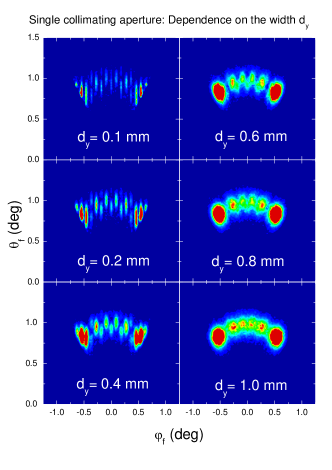
We start analyzing the influence of the width of a single collimating aperture, , which determines the effective length of the extended beam source in the direction transversal to the incidence channel. In Fig. 2 we show two-dimensional projectile distributions, as a function of and , derived within the SIVR approximation by considering single collimating slits with the same length - mm - but different . For the narrowest aperture - mm - the final angular distribution presents thin peaks associated with Bragg diffraction, which are situated at azimuthal angles that verify Schuller09
| (13) |
where is an integer number that determines the Bragg order and is the length of the reduced unit cell along the direction. From Fig. 2 we observe that the width of these Bragg peaks notoriously increases as augments. In particular, for mm, Bragg interference is almost completely blurred out and intense rainbow maxima at the outermost azimuthal angles of the angular spectrum arise Gravielle08 . For wider collimating apertures, i.e., mm, Bragg peaks fade out, giving way to supernumerary rainbow structures in the final projectile distribution. As discussed in Refs. Winter15 ; Gravielle15 , this behavior is associated with the transversal length of the area of the surface plane that is coherently illuminated by the incident beam. The transversal length of the coherently illuminated region can be estimated from Eq. (II) as Gravielle15 , being inversely proportional to , as given by Eq. (8). Hence, for the narrower collimating apertures of Fig. 2 several reduced unit cells in the direction transversal to the incidence channel become coherently illuminated by the initial wave packet, giving rise to sharp Bragg maxima. But when the width of the collimating opening augments, the number of reduced unit cells that are coherently lighted decreases, and for mm only one reduced unit cell is coherently illuminated along the direction. Consequently, interferences coming from different parallel channels, which are associated with the Bragg mechanism Schuller09 ; SchullerGrav09 , disappear and the unit-cell form factor corresponding to the interference inside one channel governs the projectile distribution SchullerGrav09 , causing supernumerary rainbow structures to be visible instead Schuller08 .
Such an effect of the width of the collimating aperture on FAD patterns was also experimentally observed Winter15 . As shown in Figs. 2 and 3 of Ref. Gravielle15 , SIVR diffraction spectra for two different collimating widths - mm and mm - compare very well with the corresponding experimental data extracted from Ref. Winter15 . For the narrowest aperture (Fig. 2 of Ref. Gravielle15 ), the experimental and theoretical distributions present well-defined Bragg peaks laying on a thick annulus, whose mean radius is approximately equal to . However, these interference structures completely vanish when the width of the opening increases, as it happens in Fig. 3 of Ref. Gravielle15 , where only maxima at the rainbow deflection angles are clearly observed.
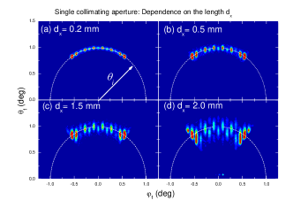
In the case of a single collimating slit, the thickness of the annulus corresponding to the distribution of scattered projectiles is controlled by the length of the collimating aperture, increasing as augments. In Fig. 3 we show angular projectile distributions derived from the SIVR approach by considering single collimating slits with the same width - mm - and different lengths. For the small square aperture of Fig. 3 (a), with mm, the Bragg peaks look like circular spots lying on a thin ring whose radius is equal to . But the thickness of this ring augments as increases, and for mm (Fig. 3 (b)) the spots become slightly elongated strips. For longer collimating apertures, with mm, not only the length of the interference fringes augments but also the different Bragg orders are situated at different radius, sampling additional interference structures along the - axis. This effect is related to the - spread of the initial wave packet, which is determined by , being proportional to as given by Eqs. (10) and (8). Large values produce a wide spread of the impact momentum normal to the surface plane, , revealing interference structures similar to those observed in the diffraction charts for different normal energies . Then, the intensity oscillations along the - axis observed for long collimating openings are exploring the surface potential for different distances to the topmost atomic plane.
III.2 Double collimating slit
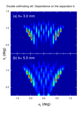
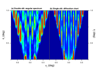
Within the limits where Eq. (II) holds, for double collimating slits the length of the coherently illuminated region along the incidence channel is governed by , instead of . Therefore, under similar collimating conditions a double-slit collimating device produces a larger - dispersion than the one corresponding to a single slit. Since a wide - spread leads to a large dispersion of the perpendicular momentum , the angular projectile distributions derived by using a double aperture with a separation of a few millimeters display interference structures in the final polar angle axis, as observed in Fig. 4. At the point that mm, the corresponding angular distribution resembles the usual diffraction chart, which is obtained with a single-slit collimator by varying the incidence angle , or what is the same, the normal energy , to cover the whole perpendicular energy spectrum. In Fig. 5 we compare the SIVR angular spectrum derived by using a double-slit collimating device with mm with the diffraction chart obtained from the SIVR approach with a single slit, both collimating apertures with the same size: mm. The similarities between the projectile distributions of Figs. 5 (a) and 5 (b) are evident, reinforcing the idea that double collimating slits might be employed to probe potential energy surfaces corresponding to different normal energies, instead of the commonly used diffraction charts. Similar angular distributions can be also obtained by employing a single slit with a sufficiently large height.
Lastly, notice that any change in the present collimation setups might affect our results and it should be specifically investigated by using a generalization of Eq. (21). Moreover, we have considered fixed incidence conditions, i.e., constant de Broglie wavelengths. However, the spatial spread of the initial wave packet depends on and , as given by Eq. (8). Then, a variation of the incidence energy or angle would modify such a spread, affecting the shape of the diffraction patterns. Also, the presence of crystal defects might play a role contributing to additional angular dispersions.
IV Conclusions
We have investigated the effect of the collimation of the incident beam on FAD patterns by considering a single- and a double- slit collimator that limits the effective size of an extended incoherent atom source. Projectile distributions originated by elastic scattering were derived from the SIVR approximation Gravielle14 by incorporating a realistic description of the coherent initial wave packet in terms of the collimating parameters. The profile of the initial wave packet was derived from a model based on the Van Cittert-Zernike theorem, which relates the effective size of the beam source with the complex degree of coherence. The theory was applied to helium atoms grazingly impinging on a LiF(001) surface, considering a fixed incidence condition and different sizes of the rectangular collimating apertures.
In this work we found that the collimating effects on the final polar and azimuthal distributions are decoupled. While the –distribution is affected by the transversal width of the collimating slit, the – distribution is governed by the geometrical characteristics of the collimating device along . For a single-slit collimator, the SIVR interference patterns are strongly affected by the width of the collimating aperture, which makes Bragg peaks (supernumerary rainbows) visible for narrow (wide) apertures. In turn, the length of the collimating opening affects the polar angle distribution of scattered projectiles, making visible additional intensity oscillations in the - axis for long collimating apertures. This effect is related to the dispersion of the normal momentum and it is more evident for a double-slit collimator.
In the case of a double-slit collimating device, the interference patterns along the final polar angle axis are governed by the separation between slits. By using separation distances between slits of several millimeters it would be possible to obtain projectile distributions covering a wide range of final polar angles. Such distributions might be used to probe the projectile-surface interaction for different normal distances. Finally, it should be stressed that actual experimental setups can involve different collimating stages, whose full description is necessary in order to obtain a proper representation of the collimating effects.
Acknowledgements.
The authors acknowledge financial support from CONICET, UBA, and ANPCyT of Argentina.*
Appendix A Complex degree of coherence for an atomic beam passing through a collimating aperture
Here we extend the Van Cittert-Zernike theorem BornWolf to evaluate the complex degree of coherence for two points - and - placed on a plane parallel to the crystal surface at a distance , which is illuminated by an extended incoherent quasi-monochromatic source after passing through a collimating aperture. For simplicity we study the simplest two-dimensional case depicted in Fig. 6, where one-dimensional emitter source and slit, with lengths and respectively, are considered. The generalization for the three-dimensional case or for two-slit collimating devices is straightforward.
As the source is composed by incoherent emitters we resort to the Van Cittert-Zernike theorem BornWolf to calculate the mutual intensity function as
| (14) |
where is the intensity of the extended source, assumed as uniform, is the wave number of the atomic beam, and , with the distances and being indicated in Fig. 6 for . By considering, as usually, that the distances and between the source and the collimator and between the collimating slit and the upon surface plane, respectively, are larger than , , and , the mutual intensity function can be reduced, except a constant factor, to :
| (15) |
where
| (16) | |||||
involves a one-dimensional integral and the asterisk indicates the complex conjugate. In Eq. (16), the function is defined as
| (17) |
for , with and the cosine and sine Fresnel integrals Abramowitz ,
| (18) |
and . The parameters and read
| (19) |
Finally, the complex degree of coherence between and is obtained from Eq. (15) as
where the function is defined by Eq. (16).
In this article, in order to derive the profile of the incident wave packet it is convenient to choose as the center of the wave packet, while represents the coherence distance. Hence, the square modulus of the corresponding complex degree of coherence can be obtained from Eq. (A) as
| (21) |
The calculation of the complex degree of coherence from Eq. (21) requires the numerical evaluation of the integral given by Eq. (16). However, analytical expressions can be obtained by considering two different mathematical limits; that is
| (22) |
where
| (23) |
Then, if the coherence size of the initial wave packet depends on , as found in Ref. Winter15 , from Eq. (23) we expect that the effective size of the source was comparatively large (in our case, 1 cm) and consequently, the distance had to be considered in the definition. For other experimental setups, the numerical calculation of Eq. (21) should be carried out in order to estimate the value of the parameter .
References
- (1) A. Schüller, S. Wethekam, and H. Winter, Phys. Rev. Lett. 98 (2007) 016103.
- (2) P. Rousseau, H. Khemliche, A.G. Borisov, and P. Roncin, Phys. Rev. Lett. 98 (2007) 016104.
- (3) H. Winter and A. Schüller, Prog. Surf. Sci. 86 (2011) 169 and references therein.
- (4) M. Debiossac et al., Phys. Rev. B 90 (2014) 155308.
- (5) A. Zugarramurdi et al., Appl. Phys. Lett. 106 (2015) 101902.
- (6) F. Aigner, N. Simonović, B. Solleder, L. Wirtz, and J. Burgdörfer, Phys. Rev. Lett. 101 (2008) 253201.
- (7) J. Lienemann et al., Phys. Rev. Lett. 106 (2011) 067602.
- (8) N. Bundaleski, P. Soulisse, A. Momeni, H. Khemliche, and P. Roncin, Nucl. Instrum. Meth. Phys. Res. B 269 (2011) 1216.
- (9) C. A. Ríos Rubiano, G.A. Bocan, J.I. Juaristi, and M.S. Gravielle, Phys. Rev. A 89 (2014) 032706.
- (10) J. Seifert, J. Lienemann, A. Schüller, and H. Winter, Nucl. Instrum. Meth. Phys. Res. B 350 (2015) 99.
- (11) M.S. Gravielle and J.E. Miraglia, Phys. Rev. A 92 (2015) 062709.
- (12) M. Born and E. Wolf, Principles of optics (Pergamon Press, Oxford, 1986), chap. 10.
- (13) M.S. Gravielle and J.E. Miraglia, Phys. Rev. A 90 (2014) 052718.
- (14) W.H. Miller, J. Phys. Chem. A 105 (2001) 2942.
- (15) C. A. Ríos Rubiano, G.A. Bocan, M.S. Gravielle, N. Bundaleski, H. Khemliche, and P. Roncin, Phys. Rev. A 87 (2013) 012903.
- (16) R. Guantes, A.S. Sanz, J. Margalef-Roig, S. Miret-Artés, Surf. Sci. Rep. 53 (2004) 199, p. 213.
- (17) J.-F. Schaff, T. Langen, and J. Schmiedmayer, Rivista del Nuovo Cimento 37 (2014) 509.
- (18) A. Tonomura, Progress in Optics 23 (North-Holland, Amsterdam, 1986) 183.
- (19) C. Cohen-Tannoudji , B. Diu , F.Laloë, Quantum Mechanics (Willey-VCH, Paris, 2011), comp GI.
- (20) Although such a large value of may be considered not in accordance with realistic experimental setups, it might be also interpreted as an effective source length due to the different collimation stages that affect actual atomic beams.
- (21) A. Schüller, and H. Winter, Nucl. Instrum. Meth. Phys. Res. B 267 (2009) 628.
- (22) M.S. Gravielle and J.E. Miraglia, Phys. Rev. A 78 (2008) 022901.
- (23) A. Schüller, H. Winter, M.S. Gravielle, J.M Pruneda, and J.E. Miraglia, Phys Rev. A 80 (2009) 062903.
- (24) A. Schüller and H. Winter, Phys. Rev. Lett. 100 (2008) 097602.
- (25) M. Abramowitz and I.A. Stegun, Handbook of Mathematical Functions with Formulas, Graphs, and Mathematical Tables. Applied Mathematics Series 55 (United States Department of Commerce, National Bureau of Standards, Dover Publications, New York, 1972).