Strong interband Faraday rotation in 3D topological insulator Bi2Se3
Abstract
The Faraday effect is a representative magneto-optical phenomenon, resulting from the transfer of angular momentum between interacting light and matter in which time-reversal symmetry has been broken by an externally applied magnetic field. Here we report on the Faraday rotation induced in the prominent 3D topological insulator Bi2Se3 due to bulk interband excitations. The origin of this non-resonant effect, extraordinarily strong among other non-magnetic materials, is traced back to the specific Dirac-type Hamiltonian for Bi2Se3, which implies that electrons and holes in this material closely resemble relativistic particles with a non-zero rest mass.
pacs:
71.70.Di, 76.40.+b, 78.30.-j, 81.05.UwThe recently emerged class of topological insulators (TIs)D. Hsieh et al. (2008); Qi and Zhang (2011); Hasan and Kane (2010) comprises materials with specific Dirac-type surface states, which continuously connect otherwise well-separated conduction and valence bands. The existence of these intriguing surface states is encoded in the specific bulk electronic band structures, which combines band inversion with time-reversal symmetry. The sensitivity to perturbations breaking the time-reversal symmetry makes TIs, and in particular their surface states, natural targets of Faraday rotation experiments Valdés Aguilar et al. (2012); Sushkov et al. (2010); Jenkins et al. (2013); Wu et al. (2015), allowing us, among other things, to trace the crossover from the topological to normal state of matter. Opening the band gap in the TI surface states should be, at subgap photon energies, manifested by a Faraday angle determined only by the fine structure constant Tse and MacDonald (2010a); Maciejko et al. (2010). Other universal Faraday rotation effects have been proposed for Landau-quantized surface states of TIs Tse and MacDonald (2010b, 2011). These become analogous to predictions for other quantum Hall systems, including graphene and electron/hole gases in conventional 2D semiconductor heterostructures Morimoto et al. (2009), which have already been tested in the very first experiments Ikebe et al. (2010); Crassee et al. (2011); Shimano et al. (2013).
In this paper, we report on a strong Faraday rotation in the well-known Bi2Se3 3D topological insulator. We show that the observed effect appears due to interband excitations in bulk, from the valence to the partially filled conduction band. The strength of the rotation, expressed in terms of the Verdet constant, is found to be extraordinary large for a non-magnetic material. This is related to the specific bulk electronic band structure of Bi2Se3, which implies that charge carriers closely resemble massive relativistic particles, with the spin-splitting large and equal for electrons and holes.
Results
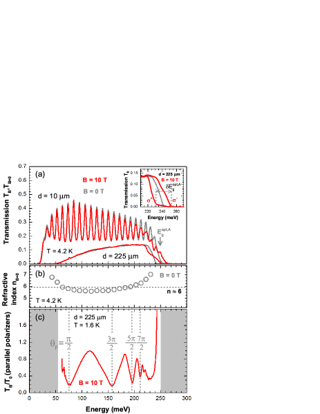
The Faraday rotation measurements have been performed on thin layers of Bi2Se3 sliced from bulk crystals (A, B and C) with various bulk electron densities (, and cm-3). The prepared specimens with various thicknesses were characterized by infrared transmission at . The typical zero-field response observed is illustrated in Fig. 1a, where transmission spectra taken on two free-standing layers prepared from the A crystal (with thicknesses of and 225 m) are plotted. For the 10-m-thick sample, the transmission window approximatively spans from the plasma frequency meV up to the interband absorption edge (optical band gap) meV. The difference between and the energy band gap , typical of doped degenerate semiconductors, is usually referred to as the Burstein-Moss shift Burstein (1954). For sample A, this implies a zero-field Fermi level of meV, assuming the parameters derived in Ref. Orlita et al., 2015 ( and meV).
The pronounced Fabry-Pérot interference pattern observed in the transmission spectrum of the 10-m-thick specimen, see Fig. 1a, allows us to estimate the refractive index of Bi2Se3 at photon energies within the window of high transparency, as shown in Fig. 1b, with the averaged value of . The absolute transmission of the 10-m-thick layer, , is close to the theoretical value for non-absorbing medium characterized by the refractive index . In the thicker sample, the below-gap absorption is no longer negligible, implying significantly lower absolute transmission and also noticeably narrower transmission window. The results obtained in transmission measurements on the other two specimens were analogous, providing us with the optical band gaps of meV and meV. The declared errors here are mostly due to the variation of the electron density across the bulk crystals.
Interestingly, the application of the magnetic field gives rise to a strong modification of the interband absorption edge of Bi2Se3. Namely, a splitting with respect to the circular polarization of the probing radiation appears, as shown in the inset of Fig. 1a. This splitting was found to be linear in and the same for all the three investigated crystals: meV/T. In the transmission spectrum taken with non-polarized (or linearly polarized) radiation, this splitting manifests itself as a characteristic step-like profile of the interband absorption edge, see Fig. 1a. This significant difference in interband absorption for circularly polarized light of the opposite helicity is the origin of the strong interband Faraday rotation discussed in this paper.
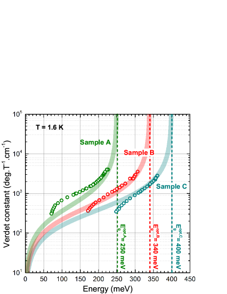
The extraordinarily strong Faraday effect can be probed using a simple configuration with the sample placed in between two co-linearly oriented polarizers. The Faraday effect is then manifested by a characteristic modulation of the relative magneto-transmission spectra , see Fig. 1c. This spectrum has been taken at T on the 225-m-thick layer prepared from the crystal A. The pronounced minima can be easily identified with particular Faraday angles , , and the corresponding Verdet constants (normalized Faraday angles), , can be calculated from curves measured at various values of . The frequency dependence of the Verdet constant, deduced for samples A, B and C, has been plotted in Fig. 2. Notably, no field-dependence of the Verdet constant has been revealed within the range of the magnetic field applied (up to 13 T).
Discussion
To account for the observed magneto-optical response let us recall the band structure of Bi2Se3. Within the past few years, the exact shape of electronic bands in this material has been subject of vast discussions. Nevertheless, Bi2Se3 is most likely a direct band-gap semiconductor, see, e.g., Refs. Yazyev et al., 2012; Aguilera et al., 2013, which can be well-described by Dirac-type models such as the one proposed in Refs. Zhang et al., 2009; Liu et al., 2010. Our recent magneto-optical study Orlita et al. (2015) implies that the conduction and valence bands are nearly parabolic with a high degree of the electron-hole symmetry, see Fig. 3. This electronic band structure can be described using a simplified Dirac-type Hamiltonian for massive particles, which contains only two parameters: the band gap and the velocity parameter . These two parameters provide us with reasonably accurate estimates for the effective masses and factors: and , respectively, where is the Dirac mass.
Large factors in Bi2Se3 give rise to a specific regime at low magnetic fields, when a pronounced spin-splitting of electronic states appears, but Landau levels are still not well resolved (), as schematically sketched in Fig. 3. Within this picture of spin-split bands, the interband absorption edge splits with respect to the circular polarization of light:
| (1) |
where is the Bohr magneton. This formula may be straightforwardly derived, using purely geometrical arguments, see Fig. 3 and its caption.
Notably, due to nearly equal factors of electrons and holes in Bi2Se3 (), a pronounced splitting of the interband absorption edge (1) only appears in this material when the conduction band is partially filled by electrons (or alternatively the valence band by holes). The observed Faraday rotation, even though primarily related to the circular dichroism of the interband absorption, is thus basically induced by the presence of free conduction-band electrons. However, this effect should be clearly distinguished from the intraband Faraday rotation due to free charge carriers, where the circular dichroism originates in cyclotron motion of particles and related resonant absorptionBennett and Stern (1965).

Importantly, the splitting (1) does not explicitly depend on the electron density, in agreement with our experiments. The carrier density only determines the saturation field , at which a full spin-polarization of electrons is achieved, Mukhopadhyay et al. (2015). Above , the formula (1) is no longer valid and the splitting saturates at when . Taking the parameters derived in Ref. Orlita et al., 2015 (, and ) we get meV/T in very good agreement with the experiment. The saturation field for the lowest doped specimen A should reach T, well above the magnetic fields applied in the experiments presented here.
The Verdet constant is proportional to the difference between refractive indices for right “+” and left “-” circularly polarized light: , which can be approximated in a weakly absorbing medium by Boswarva et al. (1962):
| (2) |
where stands for the real part of the dielectric function, and is the speed of light in vacuum.
When we neglect the contribution from all electronic bands other than the conduction and valence bands and assume the interband matrix elements to be independent of the magnetic field and momentum, Liu et al. (2010), the imaginary (dissipative) part of the dielectric function at low magnetic fields and temperatures reads, for a given circular polarization Yu and Cardona (2010):
| (3) |
where is the joint density of states and is the Heaviside step function, which describes the low-energy onset of interband absorption at the photon energy of .
Assuming strictly equal spin splitting for electrons and holes () and neglecting the anisotropy of electronic bands, the joint density of states becomes identical for both circular polarizations, , and the imaginary part of the dielectric function (3) takes the form:
| (4) |
where .
Using the Kramers-Kronig relations applied to together with Eq. 2, the Verdet constant can be expressed as:
| (5) |
Taking assumption of the full electron-hole symmetry (), we finally get, in the limit of low magnetic fields (), an approximative expression: ( is the fine structure constant):
| (6) |
It is worth noting that in the low-field limit, the density of spin-polarized carriers, , can be approximated as the spin-splitting, , multiplied by the zero-field density of states, . The Faraday angle corresponding to Eq. 6, , thus becomes directly proportional to . This may resemble the interband Faraday effect due to the Raman spin-flip of electrons bound to In-donors in CdS, reported by Romestain et al. Romestain et al. (1975), and later on, of free conduction-band electrons in InSb and HgCdTe Yuen et al. (1987); Aggarwal et al. (1988). However, the mechanism of the Faraday rotation reported here is different from that considered in Refs. Romestain et al., 1975; Yuen et al., 1987; Aggarwal et al., 1988 and is uniquely related to dipole-allowed interband absorption. While in the Raman spin-flip induced Faraday rotation, the angle becomes proportional to the spin splitting of electrons (), in our case, the resulting rotation is clearly sensitive to the spin splitting of both electrons and holes (both and factors), as seen from the initial Eq. 1.
Scaling the photon energy with respect to the optical band gap, , we get the characteristic frequency profile of the interband Faraday rotation: , . Interestingly, this profile has a considerably simpler form as compared to the expressions derived for and applied to undoped semiconductors Boswarva et al. (1962); Roth (1964); Balkanski et al. (1966); Bennett and Stern (1965). This is due to the match between the electron and hole spin splitting in Bi2Se3, , which implies the same joint density of states for both circular polarizations, and therefore, only the finite integration range in the Kramers-Kronig transformation, see Eq. 5. Another simplification, which again comes directly from the Dirac-type Hamiltonian valid for Bi2Se3, is rather high degree of electron-hole symmetry (). This allows us to express the optical band gap as .
We should stress that the formula (6) derived for the Verdet constant in Bi2Se3 does not contain any tunable parameters. The bulk band gap meV and the velocity parameter m/s are known from experiments, for instance, from our recent Landau level spectroscopy of thin Bi2Se3 layers Orlita et al. (2015). The refractive index and the optical band gaps are directly read from transmission spectra of thin specimens at , as illustrated for sample A in Figs. 1a and b.
The theoretical curves, calculated using these parameters in Eq. 6, are in good quantitative agreement with the experimentally determined Verdet constant, see Fig. 2. For the crystals B and C, the major deviations appear only at lower energies, where the contribution to the total Faraday rotation arising from the cyclotron resonance absorption Bennett and Stern (1965) (fully intraband process) is no longer negligible. For the lowest-doped sample A, the spin-splitting becomes, for the studied range of magnetic fields, comparable with the Fermi level, which brings the formula (6) close to the limit of its validity.
Let us now compare our results with the Faraday rotation on other materials, the choice of which remains, in the equivalent spectral range, still limited. Taking the reference at the wavelength 10.6 m of the CO2 laser, the highest specific interband Faraday rotation for non-magnetic materials has been reported for InSb, deg/(T.cm) Smith et al. (1962); Jiménez-González et al. (1994). Interestingly, this semiconductor has a band gap nearly identical to Bi2Se3. This rotation is at least one order of magnitude lower compared to the value we have found in Bi2Se3: deg/(T.cm), see the Verdet constant at wavelength of 10.6 m (corresponding to the photon energy of 120 meV) for the lowest doped specimen A in Fig. 2. In fact, the observed Verdet constants become comparable to values known for magnetic semiconductors, see, e.g., Ref. Gaj et al., 1978.
The relatively high Verdet constants of Bi2Se3 invoke the possibility to use it as the active medium in Faraday rotators/insulators although one has to keep in mind the Drude-type absorption on free conduction-band electrons, which lowers the overall transmission. This absorption may be reduced, by decreasing the electron density, nevertheless, this may be a challenging task for the current growth technology of this material. Moreover, this would also lower the saturation field .
It is instructive to discuss the implications of our results on other 3D TIs from the same family, such as Bi2Te3 or Sb2Te3. Most likely, their bands strongly deviate from the parabolic profiles Michiardi et al. (2014), which are characteristic of Bi2Se3, but still they are characterized by similar band gaps, and also, as seen, for instance, from ARPES experiments Hsieh et al. (2009), similar velocity parameters. Since these materials are described by the same expanded 3D Dirac Hamiltonian Liu et al. (2010); Zhang et al. (2009), we may expect the electron and hole factors to roughly follow the simple estimate deduced for Bi2Se3 in Ref. Orlita et al., 2015. This would imply an analogous splitting of the interband absorption edge given by Eq. 1 and equally strong interband Faraday effect in doped TIs.
To conclude, we have probed the Faraday rotation induced by interband excitations in a series of bulk Bi2Se3 specimens. We show that this effect is at least by an order of magnitude stronger than in other non-magnetic materials. We demonstrate that the particular strength of the effect has its origin in the relativistic-like Hamiltonian applicable to Bi2Se3 thanks to which electrons and holes behave as massive Dirac particles. A simple formula based on this two-parameter Dirac-type Hamiltonian is derived to describe this phenomenon quantitatively, requiring no tunable parameters. We also predict that similarly strong interband Faraday effect should be present in other 3D topological insulators, in particular in those from the Bi2Se3 family.
Methods: The studied Bi2Se3 crystals have been prepared using the standard Bridgman method. The starting material for growing the single crystals was prepared from the elements Bi and Se of 5N purity. Polycrystalline material was prepared from a mixture of the elements close to stoichiometry (Bi:Se = 2:3) in silica ampoules evacuated to a pressure of 10-4 Pa. The synthesis was carried out at the temperature of 1073 K. A conical quartz ampoule, containing the synthesized polycrystalline material, was then placed in the upper (warmer) part of the Bridgman furnace, where it was remelted. Then it was lowered into a temperature gradient of 80 K/cm (30 K/cm for the sample C) at a rate of 1.3 mm/h. Three bulk crystals, differing in the concentration of conduction-band electrons in the conduction band, have been chosen for this study. They were characterized by approximate electron densities , and cm-3 and denoted as samples A, B and C, respectively.
The prepared single crystals, easily cleavable along the hexagonal planes (0001), were sliced, using a microtome machine to free-standing layers with various thicknesses. All experiments, magneto-transmission and Faraday-angle measurements, were performed in the Faraday configuration with light propagating along the axis of Bi2Se3. A macroscopic area of the sample (4 mm2) was exposed to the radiation of a globar, which was analysed by a Fourier transform spectrometer and, using light-pipe optics, delivered to the sample placed in a superconducting magnet. The transmitted light was detected by a composite bolometer placed directly below the sample, kept at a temperature of 1.6 or 4.2 K. To measure the Faraday rotation, the specimens were placed in between two co-linearly oriented wire-grid polarizers defined holographically on a KRS-5 substrate. In experiments performed with circularly polarized light, a linear polarizer and a zero-order MgF2 quarter wave plate (centered at m) were used.
Authors contributions: M.O., G.M. and M.P. conceived the study. Experiments were performed by L.O., M.H., G.M., C.F., B.A.P. and M.O. The samples were prepared and characterized by C.D., A.M., G.S., A.H., M.V.Y. and R.W.M. The theoretical model was developed by M.V., M.P. and M.O. The manuscript was written by M.V. and M.O. All authors discussed the results and commented on the manuscript.
Acknowledgments: The work has been supported by the ERC project MOMB. Authors acknowledge discussions with D. M. Basko, S. A. Studenikin, T. Brauner, C. Michel, E. M. Hankiewicz and M. O. Goerbig. The work in ITME-Poland has been supported by the research project NCN UMO, 2011/03/B/ST3/03362 Polska. M.V.Y acknowledges the support from RFBR though projects 14-02-00080, 14-03-00121 and UB RAS 15-20-3-11.
Competing financial interests: The authors declare no competing financial interests.
References
- D. Hsieh et al. (2008) D. Hsieh et al., “A topological dirac insulator in a quantum spin hall phase,” Nature 452, 970–974 (2008).
- Qi and Zhang (2011) Xiao-Liang Qi and Shou-Cheng Zhang, “Topological insulators and superconductors,” Rev. Mod. Phys. 83, 1057–1110 (2011).
- Hasan and Kane (2010) M. Z. Hasan and C. L. Kane, “Colloquium: Topological insulators,” Rev. Mod. Phys. 82, 3045–3067 (2010).
- Valdés Aguilar et al. (2012) R. Valdés Aguilar, A. V. Stier, W. Liu, L. S. Bilbro, D. K. George, N. Bansal, L. Wu, J. Cerne, A. G. Markelz, S. Oh, and N. P. Armitage, “Terahertz response and colossal kerr rotation from the surface states of the topological insulator ,” Phys. Rev. Lett. 108, 087403 (2012).
- Sushkov et al. (2010) A. B. Sushkov, G. S. Jenkins, D. C. Schmadel, N. P. Butch, J. Paglione, and H. D. Drew, “Far-infrared cyclotron resonance and faraday effect in ,” Phys. Rev. B 82, 125110 (2010).
- Jenkins et al. (2013) Gregory S. Jenkins, Don C. Schmadel, Andrei B. Sushkov, H. Dennis Drew, Max Bichler, Gregor Koblmueller, Matthew Brahlek, Namrata Bansal, and Seongshik Oh, “Dirac cone shift of a passivated topological bi2se3 interface state,” Phys. Rev. B 87, 155126 (2013).
- Wu et al. (2015) Liang Wu, Wang-Kong Tse, M. Brahlek, C. M. Morris, R. Vald s Aguilar, N. Koirala, S. Oh, and N. P. Armitage, (2015), arXiv:1502.04577.
- Tse and MacDonald (2010a) Wang-Kong Tse and A. H. MacDonald, “Giant magneto-optical kerr effect and universal faraday effect in thin-film topological insulators,” Phys. Rev. Lett. 105, 057401 (2010a).
- Maciejko et al. (2010) Joseph Maciejko, Xiao-Liang Qi, H. Dennis Drew, and Shou-Cheng Zhang, “Topological quantization in units of the fine structure constant,” Phys. Rev. Lett. 105, 166803 (2010).
- Tse and MacDonald (2010b) Wang-Kong Tse and A. H. MacDonald, “Magneto-optical and magnetoelectric effects of topological insulators in quantizing magnetic fields,” Phys. Rev. B 82, 161104 (2010b).
- Tse and MacDonald (2011) Wang-Kong Tse and A. H. MacDonald, “Magneto-optical faraday and kerr effects in topological insulator films and in other layered quantized hall systems,” Phys. Rev. B 84, 205327 (2011).
- Morimoto et al. (2009) Takahiro Morimoto, Yasuhiro Hatsugai, and Hideo Aoki, “Optical hall conductivity in ordinary and graphene quantum hall systems,” Phys. Rev. Lett. 103, 116803 (2009).
- Ikebe et al. (2010) Y. Ikebe, T. Morimoto, R. Masutomi, T. Okamoto, H. Aoki, and R. Shimano, “Optical hall effect in the integer quantum hall regime,” Phys. Rev. Lett. 104, 256802 (2010).
- Crassee et al. (2011) I. Crassee, J. Levallois, A. L. Walter, M. Ostler, A. Bostwick, E. Rotenberg, T. Seyller, D. van der Marel, and A. B. Kuzmenko, “Giant faraday rotation in single- and multilayer graphene,” Nature Phys. 7, 48 (2011).
- Shimano et al. (2013) R. Shimano, G. Yumoto, J. Y. Yoo, R. Matsunaga, S. Tanabe, H. Hibino, T. Morimoto, and H. Aoki, “Quantum faraday and kerr rotations in graphene,” Nature Comm. 4, 1841 (2013).
- Burstein (1954) Elias Burstein, “Anomalous optical absorption limit in insb,” Phys. Rev. 93, 632–633 (1954).
- Orlita et al. (2015) M. Orlita, B. A. Piot, G. Martinez, N. K. Sampath Kumar, C. Faugeras, M. Potemski, C. Michel, E. M. Hankiewicz, T. Brauner, Č. Drašar, S. Schreyeck, S. Grauer, K. Brunner, C. Gould, C. Brüne, and L. W. Molenkamp, “Magneto-optics of massive dirac fermions in bulk ,” Phys. Rev. Lett. 114, 186401 (2015).
- Yazyev et al. (2012) Oleg V. Yazyev, Emmanouil Kioupakis, Joel E. Moore, and Steven G. Louie, “Quasiparticle effects in the bulk and surface-state bands of bi2se3 and bi2te3 topological insulators,” Phys. Rev. B 85, 161101 (2012).
- Aguilera et al. (2013) Irene Aguilera, Christoph Friedrich, Gustav Bihlmayer, and Stefan Blügel, “ study of topological insulators bi2se3, bi2te3, and sb2te3: Beyond the perturbative one-shot approach,” Phys. Rev. B 88, 045206 (2013).
- Zhang et al. (2009) Haijun Zhang, Chao-Xing Liu, Xiao-Liang Qi, Xi Dai, Zhong Fang, and Shou-Cheng Zhang, “Topological insulators in bi2se3, bi2te3 and sb2te3 with a single dirac cone on the surface,” Nature Phys. 5, 438–442 (2009).
- Liu et al. (2010) Chao-Xing Liu, Xiao-Liang Qi, HaiJun Zhang, Xi Dai, Zhong Fang, and Shou-Cheng Zhang, “Model hamiltonian for topological insulators,” Phys. Rev. B 82, 045122 (2010).
- Bennett and Stern (1965) Herbert S. Bennett and Edward A. Stern, “Faraday effect in solids,” Phys. Rev. 137, A448–A461 (1965).
- Mukhopadhyay et al. (2015) S. Mukhopadhyay, S. Krämer, H. Mayaffre, H. F. Legg, M. Orlita, C. Berthier, M. Horvatić, G. Martinez, M. Potemski, B. A. Piot, A. Materna, G. Strzelecka, and A. Hruban, “Hyperfine coupling and spin polarization in the bulk of the topological insulator ,” Phys. Rev. B 91, 081105 (2015).
- Boswarva et al. (1962) I. M. Boswarva, R. E. Howard, and A. B. Lidiard, “Faraday effect in semiconductors,” Proc. R. Soc. London, Ser. A, Math. 269, 125–141 (1962).
- Yu and Cardona (2010) P. Y. Yu and M. Cardona, Fundamentals of Semiconductors (Springer, Berlin Heidelberg, 2010).
- Romestain et al. (1975) R. Romestain, S. Geschwind, and G. E. Devlin, “Measurement of spin-flip-raman-scattering cross section and exchange effects for donors in cds by faraday rotation,” Phys. Rev. Lett. 35, 803–806 (1975).
- Yuen et al. (1987) S. Y. Yuen, P. A. Wolff, P. Becla, and D. Nelson, “Free-carrier spin-induced faraday rotation in hgcdte and hgmnte,” J. Vac. Sci. Technol. A 5, 3040–3042 (1987).
- Aggarwal et al. (1988) R. L. Aggarwal, R. F. Lucey, and D. P. Ryan-Howard, “Faraday rotation in the 10 m region in insb at liquid-helium temperature,” Applied Physics Letters 53 (1988).
- Roth (1964) Laura M. Roth, “Theory of the faraday effect in solids,” Phys. Rev. 133, A542–A553 (1964).
- Balkanski et al. (1966) M. Balkanski, E. Amzallag, and D. Langer, “Interband faraday rotation of ii vi compounds,” J. Phys. Chem. Solids 27, 299 – 308 (1966).
- Smith et al. (1962) S. D. Smith, C. R. Pidgeon, and V. Prosser, in Proceedings of the International Conference on the Physics of Semiconductors, Exeter, 1962, edited by A. C. Stickland (The Physical Society, London, 1962) p. 301.
- Jiménez-González et al. (1994) H. J. Jiménez-González, R. L. Aggarwal, and G. Favrot, “Infrared faraday rotation of n -type insb,” Phys. Rev. B 49, 4571–4578 (1994).
- Gaj et al. (1978) J.A. Gaj, R.R. Gala zka, and M. Nawrocki, “Giant exciton faraday rotation in cd1-xmnxte mixed crystals,” Solid State Communications 25, 193 – 195 (1978).
- Michiardi et al. (2014) Matteo Michiardi, Irene Aguilera, Marco Bianchi, Vagner Eustáquio de Carvalho, Luiz Orlando Ladeira, Nayara Gomes Teixeira, Edmar Avellar Soares, Christoph Friedrich, Stefan Blügel, and Philip Hofmann, “Bulk band structure of ,” Phys. Rev. B 90, 075105 (2014).
- Hsieh et al. (2009) D. Hsieh, Y. Xia, D. Qian, L. Wray, F. Meier, J. H. Dil, J. Osterwalder, L. Patthey, A. V. Fedorov, H. Lin, A. Bansil, D. Grauer, Y. S. Hor, R. J. Cava, and M. Z. Hasan, “Observation of time-reversal-protected single-dirac-cone topological-insulator states in and ,” Phys. Rev. Lett. 103, 146401 (2009).