Compressive Sensing Based Multi-User Detector for the Large-Scale SM-MIMO Uplink
Abstract
Conventional spatial modulation (SM) is typically considered for transmission in the downlink of small-scale MIMO systems, where a single one of a set of say antenna elements (AEs) is activated for implicitly conveying bits. By contrast, inspired by the compelling benefits of large-scale MIMO (LS-MIMO) systems, here we propose a LS-SM-MIMO scheme for the uplink (UL), where each user having multiple AEs but only a single radio frequency (RF) chain invokes SM for increasing the UL-throughput. At the same time, by relying on hundreds of AEs but a small number of RF chains, the base station (BS) can simultaneously serve multiple users whilst reducing the power consumption. Due to the large number of AEs of the UL-users and the comparably small number of RF chains at the BS, the UL multi-user signal detection becomes a challenging large-scale under-determined problem. To solve this problem, we propose a joint SM transmission scheme and a carefully designed structured compressive sensing (SCS)-based multi-user detector (MUD) to be used at the users and BS, respectively. Additionally, the cyclic-prefix single-carrier (CPSC) is used to combat the multipath channels, and a simple receive AE selection is used for the improved performance over correlated Rayleigh-fading MIMO channels. We demonstrate that the aggregate SM signal consisting of multiple UL-users’ SM signals in one CPSC block appears the distributed sparsity. Moreover, due to the joint SM transmission scheme, aggregate SM signals in the same transmission group exhibit the group sparsity. By exploiting these intrinsically sparse features, the proposed SCS-based MUD can reliably detect the resultant SM signals with low complexity. Simulation results demonstrate that the proposed SCS-based MUD achieves a better signal detection performance than its counterparts even with higher UL-throughtput.
Index Terms:
Large-scale MIMO (LS-MIMO), spatial modulation (SM), multi-user detector, compressive sensing.I Introduction
A widely recognized consensus is that the fifth-generation (5G) systems will be capable of providing significant energy efficiency and system capacity improvements [1, 2]. Promising techniques, such as large-scale MIMO (LS-MIMO) and spatial modulation (SM)-MIMO systems are considered as potent candidates for 5G [1, 2, 3, 4, 5]. LS-MIMO employing hundreds of antenna elements (AEs) at the base station (BS) is capable of improving the spectral efficiency by orders of magnitude, but it suffers from the nonnegligible power consumption and hardware cost due to one specific RF chain usually required by every AE [5]. By using a reduced number of RF chains, the emerging SM-MIMO activates part of available AEs to transmit extra information in the spatial domain, and it has attracted much attention due to its high energy efficiency and reduced hardware cost [5]. However, conventional SM-MIMO is usually considered in the downlink of small-scale MIMO systems, and therefore its achievable capacity is limited. Individually, both technologies have their own advantages and drawbacks. By an effective combination of them together, one can envision the win-win situation. SM-MIMO is attractive for LS-MIMO systems, since the reduced number of required RF chains in SM-MIMO can reduce the power consumption and hardware cost in conventional LS-MIMO systems. Moveover, hundreds of AEs used in LS-MIMO can improve the system throughput of SM-MIMO. Such reciprocity enables LS-MIMO and SM-MIMO to enjoy the apparent compatibility.
In this paper, we propose a LS-SM-MIMO scheme for intrinsically amalgamating the compelling benefits of both LS-MIMO and SM-MIMO for the 5G uplink (UL) over frequency-selective fading channels. In the proposed scheme, each UL-user equipped with multiple AEs but only a single RF chain invokes SM for increasing the UL-throughput, and the cyclic-prefix single-carrier (CPSC) transmission scheme is adopted to combat the multipath channels [6]. At the BS, hundreds of AEs but only dozens of RF chains are employed to simultaneously serve multiple users, and a direct AE selection scheme is used to improve the system performance over correlated Rayleigh-fading MIMO channels at the BS [7]. The proposed scheme can be adopted in conventional LS-MIMO as a specific UL-transmission mode for reducing the power consumption, or altarenatively, for energy- and cost-efficient LS-SM-MIMO, where joint benefits of efficient AE selection [7], transmit precoding [8], and channel estimation [9] can be readily exploited. To sum up, the proposed scheme inherits the advantages of LS-MIMO and SM-MIMO, while reducing the power consumption and hardware cost.
A challenging problem in the proposed UL LS-SM-MIMO scheme is how to realize a reliable multi-user detector (MUD) with low complexity. The optimal maximum likelihood (ML) signal detector suffers from the excessive complexity. Conventional sphere decoding detectors cannot be readily used in multi-user scenarios and may still appear the high complexity for LS-SM-MIMO [10]. Existing low-complexity linear signal detectors, e.g., the minimum mean square error (MMSE)-based signal detector, perform well for conventional LS-MIMO systems [4]. However, they are unsuitable for the proposed LS-SM-MIMO UL-transmission, since the large number of transmit AEs of the UL-users and the reduced number of receive RF chains at the BS make the UL multi-user signal detection be a large-scale under-determined/rank-deficient problem. The authors of [11, 13, 12] proposed compressive sensing (CS)-based signal detectors to solve the under-determined signal detection problem in SM-MIMO systems, but they only considered the single-user small-scale SM-MIMO systems in the downlink.
Against this background, our new contribution is that we exploit the specific signal structure in the proposed multi-user LS-SM-MIMO UL-transmission, where each user only activates a single AE in each time slot. Hence the SM signal of each UL-user is sparse with the sparsity level of one, and the aggregate SM signal consisting of multiple UL-users’ SM signals in one CPSC block exhibits a certain distributed sparsity, which can be beneficially exploited for improving the signal detection performance at the BS. Moreover, we propose a joint SM transmission scheme for the UL-users in conjunction with an appropriately structured compressive sensing (SCS)-based MUD at the BS. The proposed SCS-based MUD is specifically tailored to leverage the inherently distributed sparsity of the aggregate SM signal and the group sparsity of multiple aggregate SM signals owing to the joint SM transmission scheme for reliable signal detection performance. Our simulation results demonstrate that the proposed SCS-based MUD is capable of outperforming the conventional detectors even with higher UL-throughput.
The rest of the paper is organized as follows. Section II introduces the system model of the proposed LS-SM-MIMO scheme. Section III specifies the proposed joint SM transmission and SCS-based MUD. Section IV provides our simulation results. Section V concludes this paper.
Throughout this paper, lower-case and upper-case boldface letters denote vectors and matrices, respectively, while , , and denote the transpose, conjugate transpose, Moore-Penrose matrix inversion, and the integer floor operators, respectively. The and norm operations are given by and , respectively. The support set of the vector is denoted by , and denotes the th entry of the vector . Additionally, denotes the entries of defined in the set , denotes the sub-matrix whose columns comprise the columns of that are defined in , and denotes the sub-matrix whose rows comprise the rows of that are defined in . The expectation operator is given by . if and , while if and .
II System Model
We first introduce the proposed LS-SM-MIMO scheme and then focus our attention on the UL-transmission with an emphasis on the multi-user signal detection.
II-A Proposed Multi-User LS-SM-MIMO Scheme
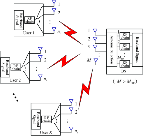
As shown in Fig. 1, we consider the proposed LS-SM-MIMO from both the BS side and the user side. For conventional LS-MIMO, the number of AEs employed by the BS is equal to the number of its RF chains [4]. However, the BS in LS-SM-MIMO, as shown in Fig. 1, is equipped with a much smaller number of RF chains than the total number of AEs , i.e., we have . Conventional LS-MIMO systems typically assume single-antenna users [4]. By contrast, in the proposed scheme, each user is equipped with AEs but only a single RF chain, and SM is adopted for the UL-transmission, where only one of the available AEs is activated for data transmission. It has been shown that the main power consumption and hardware cost of cellular networks comes from the radio access network [1]. Hence, using a reduced number of expensive RF chains compared to the total number of AEs at the BS can substantially reduce both the power consumption and the hardware cost for the operators. Meanwhile, it is feasible to incorporate several AEs and a single RF chain in the handsets. The resultant increased degrees of freedom in the spatial domain may then be exploited for improving the UL-throughput. The proposed scheme can be considered as an optional UL-transmission mode in conventional LS-MIMO systems, where AE selection schemes may be adopted for beneficially selecting the most suitable AEs at the BS to receive UL SM signals [7]. Alternatively, it can also be used for the UL of LS-SM-MIMO, when advantageously combining transmit precoding, receive AE selection, and channel estimation [8, 7, 9].
II-B Uplink Multi-User Transmission
We first consider the generation of SM signals at the users. The SM signal transmitted by the th user in a time slot consists of two parts: the spatial constellation symbol and the signal constellation symbol . is generated by mapping bits to the index of the active AE, and typically the user terminal employs AEs, where is a positive integer. Due to only a single RF chain employed at each user, only one entry of associated with the active AE equals one, and the rest of the entries of are zeros, i.e., we have
| (1) |
where is the spatial constellation symbol set. The signal constellation symbol comes from the -ary modulation, i.e., , where is the signal constellation symbol set (e.g., 64QAM) of size . Hence, each UL-user’s SM signal carries the information of bits per channel use (bpcu), and the overall UL-throughput is bpcu. Users utilize the CPSC scheme to transmit SM signals [6]. Each CPSC block consists of a cyclic-prefix (CP) with the length of and the following data block with the length of . Hence the length of each CPSC block is . CP can be used to combat the multipath channels with the length of . The data block consists of successive SM signals.
At the receiver, due to the reduced number of RF chains at the BS, only receive AEs can be exploited to receive signals, where existing receive AE selection schemes can be adopted to preselect receive AEs for achieving an improved signal detection performance [7]. Since the BS can serve users simultaneously, after the removal of CP, the received signal for in the th time slot for one CPSC block, can be expressed as
| (2) |
where is the th user’s MIMO channel matrix for the th multipath component, , the set is determined by the used AE selection scheme, elements of with the cardinality of are uniquely selected from the set , has one nonzero entry, and is the additive white Gaussian noise (AWGN) vector with entries obeying the independent and identically distributed (i.i.d.) circular symmetric complex Gaussian distribution with zero mean and a variance of per dimension, denoted by . , entries of obey the i.i.d. , with the correlation coefficient and with the correlation coefficient are correlation matrices at the users and BS, respectively. The element of the th row and th column of () is (). For correlated Rayleigh-fading MIMO channels, the specific or receive AE selection scheme has an impact on the system performance. In this paper, the direct AE selection scheme is used to maximize the minimum geometric distance between any pair of the selected AEs [7]. For uniform linear array (ULA), with . (2) can be further expressed as
| (3) |
by defining and . By considering SM signals in one CPSC block, we can further obtain
| (4) |
where , the aggregate SM signal , , and
| (5) |
The SNR at the receiver is defined by .
To detect the aggregate SM signal from (4), the optimal signal detector relies on the ML algorithm:
| (6) |
whose complexity increases exponentially with the number of users, since the size of the search set for the ML detector is . This excessive complexity can be unaffordable in practice. To reduce the complexity, near-optimal sphere decoding detectors have been proposed [10], but their complexity may still remain high, particularly for the systems supporting large , , , and [11]. In conventional LS-MIMO systems, low-complexity linear signal detectors (e.g., the MMSE-based signal detector) have been shown to be near-optimal since and lead the multi-user signal detection to be an over-determined problem [4]. However, in the proposed scheme, we have . Hence the multi-user signal detection problem (6) represents a large-scale under-determined problem. Consequently, the conventional linear signal detectors perform poorly in the proposed LS-SM-MIMO [11]. By exploiting the sparsity of SM signals, the authors of [11, 13, 12] have proposed the concept of CS-based signal detectors for the downlink of small-scale SM-MIMO operating in a single-user scenario. However, these signal detectors are unsuitable for the proposed multi-user scenarios. Observe from (1) that is a sparse signal having a sparsity level of one. Hence the aggregate SM signal which consists of multiple users’ SM signals in time slots exhibits the distributed sparsity with the sparsity level of . This property of inspires us to exploit SCS theory for the multi-user signal detection [14]. To further improve the signal detection performance and to increase the system’s throughput, we propose a joint SM transmission scheme and an SCS-based MUD, which will be detailed in the next section.
III SCS-Based MUD for LS-SM-MIMO UL
To solve the multi-user signal detection of our UL LS-SM-MIMO system, we first propose a joint SM transmission scheme to be employed at the users. Accordingly, an SCS-based low-complexity MUD is developed at the BS, whereby the distributed sparsity of the aggregate SM signal and the group sparsity of multiple aggregate SM signals are exploited. Moreover, the computational complexity of the proposed SCS-based MUD is discussed.
III-A Joint SM Transmission Scheme at the Users
For the th user in the th time slot, every successive CPSC block are considered as a group and share the same spatial constellation symbol, namely,
| (7) |
where we introduce the superscript to denote the th CPSC block, and is typically small, e.g., . In CS theory, the specific signal structure, where share a common support is often referred to as group sparsity. Similarly, the aggregate SM signals also have the group sparsity, i.e.,
| (8) |
Although exhibiting group sparsity may slightly reduce the information carried by the spatial constellation symbols, it is also capable of reducing the number of the RF chains required according to the SCS theory, whilst simultaneously improving the total bit error rate (BER) of the entire system even with higher UL-throughput. This conclusion will be confirmed by our simulation results.
III-B SCS-Based MUD at the BS
According to (4), the received signals at the BS in the same group can be expressed as
| (9) |
where denotes the received signal in the th CPSC block, while and are the effective MIMO channel matrix and the AWGN vector, respectively.
The intrinsically distributed sparsity of and the under-determined nature of (9) inspire us to solve the signal detection problem based on CS theory, which can efficiently acquire the sparse solutions to under-determined linear systems. Moreover, the different aggregate SM signals in (9) can be jointly exploited for improving the signal detection performance due to the group sparsity of . Thus, by considering both the distributed sparsity and the group sparsity of the aggregate SM signals, the multi-user signal detection at the BS can be formulated as the following optimization problem
| (10) |
Our proposed SCS-based MUD solves the optimization problem (10) with the aid of two steps. In the first step, we estimate the spatial constellation symbols, i.e., the indices of users’ active AEs in successive CPSC blocks. In the second step, we infer the legitimate signal constellation symbols of the users in CPSC blocks.
III-B1 Step 1. Estimation of Spatial Constellation Symbols
We propose a group subspace pursuit (GSP) algorithm developed from the classical subspace pursuit (SP) algorithm of [15] to acquire the sparse solution to the large-scale under-determined problem (10), where both the apriori sparse information (i.e., ) and the group sparsity of are exploited for improving the multi-user signal detection performance. The proposed GSP algorithm is described in Algorithm 1, which estimates SM signal . Hence, the estimated spatial constellation symbol is .
Compared to the classical SP algorithm, the proposed GSP algorithm exploits the distributed sparsity and group sparsity of . More explicitly, consists of the low-dimensional sparse vectors , where each has the known sparsity level of one, and the aggregate SM signals appear the group sparsity. Specifically, the differences between the proposed GSP algorithm and the classical SP algorithm lie in the following two aspects: 1) the identification of support set including the steps of preliminary support set and final support set as shown in Algorithm 1; and 2) the joint processing of . First, for the support selection, taking the step of preliminary support set for instance, when selecting the preliminary support set, the classical SP algorithm selects the support set associated with the first largest values of the global correlation result . By contrast, the proposed GSP algorithm selects the support set associated with the largest value from the local correlation result in each . In this way, the distributed sparsity of the aggregate SM signal can be exploited for improved signal detection performance. Second, compared with the classical SP algorithm, the proposed GSP algorithm jointly exploits the correlated signals having the group sparsity, which can bring the further improved signal detection performance.
It should be noted that even for the special case of , i.e., without using the joint SM transmission scheme, the proposed GSP algorithm still achieves a better signal detection performance than the classical SP algorithm when handling the aggregate SM signal, since the inherently distributed sparsity of the aggregate SM signal is leveraged to improve the signal detection performance.
III-B2 Step 2. Acquisition of Signal Constellation Symbols
Following Step 1, we can also acquire a rough estimate of the signal constellation symbol for each user in each time slot. By searching for the minimum Euclidean distance between this rough estimate of the signal constellation symbol and the legitimate constellation symbols of , we can obtain the final estimate of signal constellation symbols.
III-C Computational Complexity
The optimal ML signal detector has a prohibitively high computational complexity of according to (6). The sphere decoding detectors [10] are indeed capable of reducing the computational complexity, but they may still suffer from an unaffordable complexity, particularly for large , , and values. By contrast, the conventional MMSE-based detector for LS-MIMO and CS-based detector [13] for small-scale SM-MIMO enjoy the low complexity of and , respectively. For the proposed SCS-based MUD, most of the computational requirements are imposed by the least squares (LS) operations, which has a complexity of [16]. Consequently, the computational complexity per CPSC block is , since successive aggregate SM signals are jointly processed. Compared with conventional signal detectors, the proposed SCS-based MUD benefits from a substantially lower complexity than the ML signal detector or the sphere decoding detectors, and it has a similar low complexity to the conventional MMSE-based and CS-based signal detectors.
IV Simulation Results
A simulation study was carried out to compare the performance of the proposed SCS-based MUD with that of the MMSE-based signal detector [4] and the CS-based signal detector [13]. In the LS-SM-MIMO system considered, the BS with ULA employed a large number of AEs but a much smaller number of RF chains , while users employing AEs but only a single RF chain simultaneously use CPSC scheme with and to transmit SM signals to the BS. The total BER including the spatial constellation symbol and the signal constellation symbol were investigated.
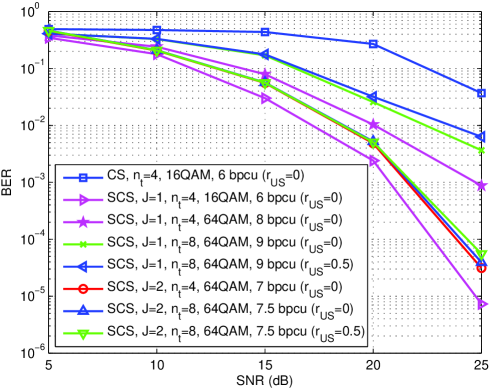
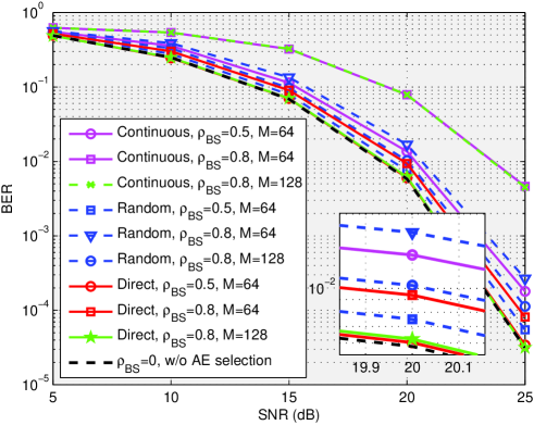
Fig. 2 compares the total BERs achieved by the proposed SCS-based MUD with different AE selection schemes, where , , 64QAM, , , and are considered. The continuous AE selection scheme means to select continuous AEs, i.e., with . The random AE selection scheme means that elements of are uniquely selected from the set randomly. The direct AE selection scheme [7] has been provided in Section II-B. Besides, the BER achieved by the SCS-based MUD with is considered as the performance bound, since and imply the uncorrelated Rayleigh-fading MIMO channels. From Fig. 2, it can be observed that the direct AE selection scheme outperforms two other AE selection schemes. Moreover, for a certain AE selection scheme, the BER performance degrades when or increases. For the direct AE selection scheme, the BER performance with the case of , and the case of , approaches the BER achieved over uncorrelated Rayleigh-fading MIMO channels, which indicates the near-optimal performance of the direct AE selection scheme.
Fig. 3 compares the total BERs achieved by CS-based signal detector and the proposed SCS-based MUD against different SNR’s in LS-SM-MIMO, where , , , , and the direct AE selection scheme is considered. The SCS-based MUD outperforms the CS-based signal detector even for , since the distributed sparsity of the aggregate SM signal is exploited. For the SCS-based MUD, the BER performance improves when increases, at the cost of the reduced UL-throughput. To mitigate this issue, the larger number of AEs can be used at the users to achieve the higher modulation order of the spatial constellation symbol set. Specifically, by increasing from 4 to 8, the UL-throughput of the SCS-based MUD can increase, but more AEs at the user indicates the larger . When increases, the BER performance of the SCS-based MUD with degrades obviously. By contrast, when increases, the BER performance loss of the SCS-based MUD with can be nonnegligible, even when the larger for the larger is considered.
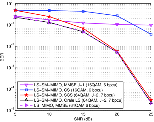
Fig. 4 depicts the total BERs achieved by different signal detectors against different SNR’s in the proposed LS-SM-MIMO, where , , , , , , and the direct AE selection scheme is considered. In Fig. 4, we also provide the oracle LS-based signal detector with the known spatial constellation symbol perfectly known at the BS for the proposed LS-SM-MIMO with , 64QAM and MMSE-based signal detector for LS-MIMO with 64QAM, where both of them only consider the BER of signal constellation symbol. Here we consider LS-MIMO uses the same number of RF chains to serve 8 single-antenna users over uncorrelated Rayleigh-fading channels. The superior performance of our SCS-based MUD to the MMSE-based and CS-based signal detectors is clear. Moreover, the performance gap between the oracle LS-based signal detector with 7 bpcu and the proposed SCS-based MUD with 7 bpcu is less than 0.5 dB. Note that the oracle LS-based signal detector only considers the BER of signal constellation symbol, while the proposed SCS-based MUD considers both the spatial and signal constellation symbols. Finally, compared with the conventional LS-MIMO with MMSE-based signal detector (6 bpcu), our proposed UL LS-SM-MIMO and the associated SCS-based MUD (7bpcu) only suffers from a negligible BER loss, which confirmed the improved UL-throughput of the proposed LS-SM-MIMO scheme.
V Conclusions
We have proposed a LS-SM-MIMO scheme for the UL-transmission. The BS employs a large number of AEs but a much smaller number of RF chains, where a simple receive AE selection scheme is used for the improved performance. Each user equipped with multiple AEs but only a single RF chain uses CPSC to combat multipath channels. SM has been adopted for the UL-transmission to improve the UL-throughput. The proposed scheme is especially suitable for scenarios, where a large number of low-cost AEs can be accommodated, and both the power consumption as well as hardware cost are heavily determined by the number of RF chains. Due to the reduced number of RF chains at the BS and multiple AEs employed by each user, the UL multi-user signal detection is a challenging large-scale under-determined problem. We have proposed a joint SM transmission scheme at the users to introduce the group sparsity of multiple aggregate SM signals, and a matching SCS-based MUD at the BS has been proposed to leverage the inherently distributed sparsity of the aggregate SM signal as well as the group sparsity of multiple aggregate SM signals for reliable multi-user signal detection performance. The proposed SCS-based MUD enjoys the low complexity, and our simulation results have demonstrated that it performs better than its conventional counterparts with even much higher UL-throughput.
References
- [1] M. D. Renzo, H. Haas, A. Ghrayeb, S. Sugiura, and L. Hanzo, “Spatial modulation for generalized MIMO: Challenges, opportunities and implementation,” Proc. IEEE, vol. 102, no. 1, pp. 56–103, Jan. 2014.
- [2] A. Younis, R. Mesleh, M. Di Renzo, and H. Haas, “Generalised spatial modulation for large-scale MIMO,” in Proc. European Signal Process. Conf. 2014 (EUSIPCO’14), pp. 346-350, Sep. 2016.
- [3] S. Ganesan, R. Mesleh, H. Haas, C. Ahn, and S. Yun, “On the performance of spatial modulation OFDM,” in Proc. 40th Asilomar Conf. Signals, Syst. Comput., pp.1825-1829, Oct. 2006.
- [4] F. Rusek, et al. “Scaling up MIMO: Opportunities and challenges with very large arrays,” IEEE Signal Process. Mag., vol. 30, no. 1, pp. 40-60, Jan. 2013.
- [5] N. Serafimovski, A. Younis, R. Mesleh, P. Chambers, M. Di Renzo, C. Wang, P.M. Grant, M.A. Beach, and H. Haas, “Practical implementation of spatial modulation,” IEEE Tran. Vech. Techn., vol. 62, no. 9, pp. 4511-4523, Jan. 2013.
- [6] P. Som and A. Chockalingam, “Spatial modulation and space shift keying in single carrier” in Proc. IEEE Int. Symp. PIMRC, pp. 1062-1067, Sep. 2012.
- [7] X. Wu, M. Di Renzo, and H. Haas, “Adaptive selection of antennas for optimum transmission in spatial modulation,” IEEE Tran. Wireless Commun., vol. 14, no. 7, pp. 36303641, Jul. 2015.
- [8] S. Narayanan, M.J. Chaudhry, A. Stavridis, M. Di Renzo, F. Graziosi, and H. Haas, “Multi-user spatial modulation MIMO” in Proc. IEEE WCNC, pp. 671-676, Apr. 2014.
- [9] X. Wu, H. Claussen, M. D. Renzo, and H. Haas, “Channel estimation for spatial modulation,” IEEE Tran. Commun., vol. 62, no. 12, pp. 4362-4372, Dec. 2014.
- [10] A. Younis, S. Sinanovic, M. Di Renzo, R. Mesleh, and H. Haas, “Generalised sphere decoding for spatial modulation,” IEEE Trans. Commun., vol. 61, no. 7, pp. 2805-2815, Jul. 2013.
- [11] W. Liu, N. Wang, M. Jin, and H. Xu, “Denoising detection for the generalized spatial modulation system using sparse property,” IEEE Commun. Lett., vol. 18, no. 1, pp. 22-25, Jan. 2014.
- [12] B. Shim, S. Kwon, and B. Song, “Sparse detection with integer constraint using multipath matching pursuit,” IEEE Commun. Lett., vol. 18, no. 10, pp. 1851-1854, Oct. 2014.
- [13] C. Yu, S. Hsieh, H. Liang, C. Lu, W. Chung, S. Kuo, and S. Pei, “Compressed sensing detector design for space shift keying in MIMO systems,” IEEE Commun. Lett., vol. 16, no. 10, pp. 1556-1559, Oct. 2012.
- [14] M. F. Duarte and Y. C. Eldar, “Structured compressed sensing: From theory to applications,” IEEE Trans. Signal Process., vol. 59, no. 9, pp. 4053–4085, Sep. 2009.
- [15] W. Dai and O. Milenkovic, “Subspace pursuit for compressive sensing signal reconstruction,” IEEE Trans. Inf. Theory, vol. 55, no. 5, pp. 2230–2249, May 2009.
- [16] A. Björck, Numerical Methods for Matrix Computations. Springer International Publishing AG, 2014.