Writing a skyrmion on multiferroic materials
Abstract
This paper reports on a theoretical proposal for electrical creation of magnetic skyrmions on a thin-film specimen of a multiferroic chiral magnet by local application of an electric field, instead of an electric current, via an electrode tip. This method can be traced back to the mutual coupling between skyrmion spins and the electric polarizations in multiferroics, and represents a unique technique for use in potential skyrmion-based memory devices without Joule-heating losses.
Magnetic skyrmions, vortex-like topological spin textures realized in chiral magnets Bogdanov89 ; Muhlbauer09 ; YuXZ10N , are attracting major research interest because they offer numerous advantages for applications as information carriers in future storage devices, including (1) nanoscale size, (2) topologically protected stability, (3) comparatively high transition temperatures, and (4) ultralow energy consumption when driving their motion. Specifically, it was proved that skyrmions in metals can be driven by a tiny electric current via spin-transfer torques, where the threshold current density is five or six orders of magnitude lower than that required to move other magnetic structures Jonietz10 ; YuXZ12 ; Schulz12 ; Everschor11 ; ZangJ11 ; Iwasaki13a ; Iwasaki13b . This finding stimulated research into novel techniques to manipulate (write, delete, read, and drive) skyrmions Nagaosa13 ; Fert13 ; Sampaio13 .
Metallic B20 alloys have been the only class of materials that have skyrmion phase. However, an insulating skyrmion phase was discovered for the first time in 2012 in Cu2OSeO3 Seki12a ; Adams12 ; Seki12b , in which the noncollinear skyrmion spin structure induces electric polarizations through relativistic spin-orbit interactions, and the system has a multiferroic nature Seki12a ; Seki12c . This multiferroicity offers an opportunity to manipulate skyrmions using electric fields rather than electric currents White12 ; White14 , which allows us to further reduce energy consumption because electric fields in insulators do not produce Joule-heating energy losses.
To use multiferroic skyrmions as information carriers, it is necessary to establish an efficient method to create skyrmions using electric fields. In this paper, taking Cu2OSeO3 as an example of a skyrmion-hosting multiferroic material, we theoretically propose that skyrmions can be created very rapidly (within a few nanoseconds) on a thin film by applying a local electric field via an electrode tip. The applied electric field induces the local magnetization reversal required to form the topological spin textures by modulating the spatial configurations of the electric polarizations. This phenomenon can be traced back to magnetoelectric coupling between the swirling skyrmion spins and electric polarizations of relativistic origin. The microscopic mechanism is thus essentially distinct from the spin-transfer torque, which is the usual channel for electrical control of magnetism in metallic magnets. Our proposal may potentially lead to a unique technique for future skyrmion-based memory devices.
The crystal structure of Cu2OSeO3 belongs to the chiral cubic P213 space group, which is equivalent to B20 compounds but has different atomic coordinates Seki12a . There are two inequivalent Cu2+ sites with a nominal ratio of 3:1; one is surrounded by a square pyramid of oxygen ligands, while the other is surrounded by a trigonal bipyramid. The magnetic structure of Cu2OSeO3 consists of a network of tetrahedra, where each tetrahedron is composed of four Cu2+ (=1/2) ions at the apexes with a three-up and one-down type ferrimagnetic spin arrangement below 58 K Bos08 ; Belesi10 .
A continuum spin model was proposed in 1980 to describe the competition between the ferromagnetic-exchange interaction and the Dzyaloshinskii-Moriya interaction in chiral cubic magnets under an external magnetic field Bak80 . For a numerical treatment of this continuum model, we divide the space into square meshes to obtain a classical Heisenberg model on the two-dimensional lattice YiSD09 . The Hamiltonian of this lattice spin model is given by,
| (1) | |||||
where =(0,0,) is a static magnetic field perpendicular to the plane. We use =3 meV and =0.09 to reproduce the magnetic transition temperature (60 K) and skyrmion size (50 nm) observed in Cu2OSeO3 Seki12a . All spin textures treated in this study have slow spatial variations, and their spins are thus nearly decoupled from the background lattice structure. This justifies our treatment based on a spin model with coarse-grained magnetizations on the simple square lattice although the real Cu2OSeO3 crystal has a rather complicated structure.
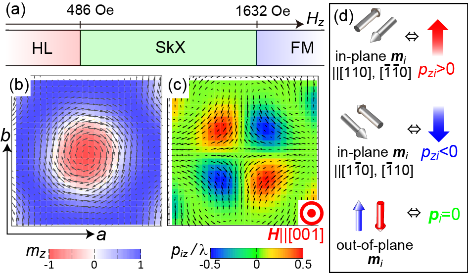
Figure 1(a) shows the ground-state phase diagram of this model as a function of the magnetic field normal to the thin-film plane. We find that the helimagnetic phase, the skyrmion crystal phase, and the field-polarized ferromagnetic phase emerge successively as increases. The critical fields here are 486 Oe and 1632 Oe, respectively. This theoretical phase diagram accurately reproduces successive phase transitions observed in thin-film samples of Cu2OSeO3 at low temperatures Seki12a .
Importantly, skyrmions in chiral magnets emerge not only in crystallized form, as observed in the skyrmion crystal phase Muhlbauer09 ; YuXZ10N ; Seki12a ; Adams12 , but also as individual defects in the ferromagnetic background YuXZ10N . These skyrmion defects are also stable because of their topological protection. In the following, we demonstrate that isolated skyrmions can be created by local application of an electric field to a thin-film sample via an electrode tip.
The noncollinear skyrmion spin texture in insulators is expected to induce electric polarizations via relativistic spin-orbit interactions. The emergence of skyrmion-induced electric polarizations was indeed observed experimentally Seki12a ; Seki12c . When local magnetization is assumed for the th crystallographic unit cell, the cubic crystal symmetry allows the emergence of local polarization in the following form:
| (2) |
Here, the coefficient is evaluated to be = Cm using data from the polarization measurements Seki12a ; Seki12c . Using this formula, one can calculate the spatial distributions of induced by the skyrmion magnetizations [Fig. 1(b)], which depends on the choice of thin-film plane. In Fig. 1(c), calculated local directions of on the [001] plane are visualized. Comparison of Fig. 1(b) with Fig. 1(c) indicates that the in-plane induces a finite out-of-plane , while the out-of-plane does not induce as summarized in Fig. 1(d). We also find that when [110] or [0], while when [10] or [10].
The coupling between magnetism and electricity offers an opportunity to manipulate magnetic skyrmions electrically by modulating the spatial distributions of their electric polarizations. We investigate dynamic processes of skyrmion creation under a local electric field [see Fig. 2(a)] by micromagnetic simulations based on the Landau-Lifshitz-Gilbert equation:
| (3) |
where
| (4) |
Here, is the model Hamiltonian (1), while represents the coupling between the local polarizations and the electric field , which is given by
| (5) |
This equation combined with Eq. (2) describes the coupling between the electric field and the magnetizations . The electric field =(0,0,) is applied for a fixed time to sites within a circular area with diameter of sites [see Fig. 2(b)]. Calculations are performed using a system of sites with an open boundary condition. The Gilbert damping coefficient is fixed at 0.04.
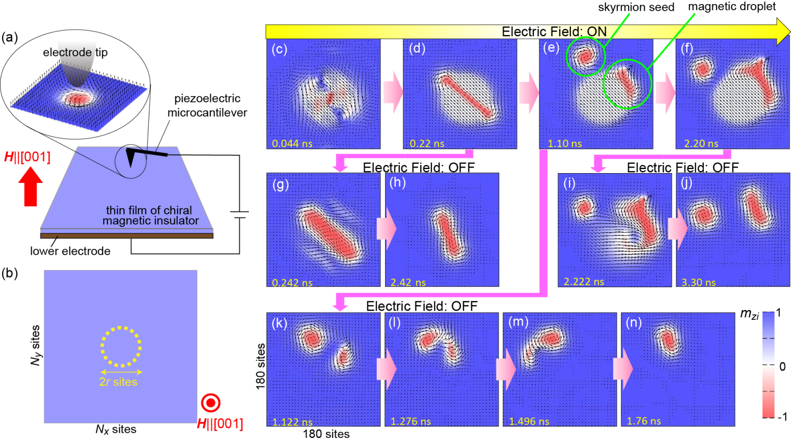
Figures 2(c)-(n) show snapshots of dynamical processes of electrical skyrmion creation simulated for Oe, V/m, (, )=(320, 320) and sites. The relevant area with 180180 sites around the -field area is magnified. The axis is set to be parallel to [001]. Local application of the -field to a uniform ferromagnetic state with causes local reversal of to at a small spot within the -field area [Fig. 2(c)]. This -reversed spot grows into a line-shaped structure [Fig. 2(d)], which has a finite skyrmion number . Therefore, if we switch off the -field at this point, we obtain a single skyrmion after relaxation of the spatial distribution of , as shown in the process of Figs. 2(c)(d)(g)(h).
However, if we continue to apply the -field, this -reversed line becomes kicked out of the -field area because the area of with 0 is energetically unfavorable under the condition of , and breaks into two parts; the first is a skyrmion seed with perfectly reversed , while the other is a magnetic droplet with imperfect reversal Mohseni13 . The skyrmion number is for the skyrmion seed, but it is zero for the magnetic droplet. The total skyrmion number is thus conserved upon collapse of the -reversed line. If we switch off the -field at this point, the skyrmion seed grows into a skyrmion, whereas the magnetic droplet vanishes or is absorbed by the skyrmion seed. Eventually, we obtain a single skyrmion again, as shown in the process of Figs. 2(c)(d)(e)(k)(l)(m)(n). If we continue to apply the -field, the magnetic droplet then grows into a skyrmion seed with perfect reversal [Fig. 2(f)]. In this case, we obtain a pair of skyrmions after the -field is switched off, as shown in the process of Figs. 2(c)(d)(e)(f)(i)(j). We can therefore control the number of skyrmions created by tuning the duration of the -field application.
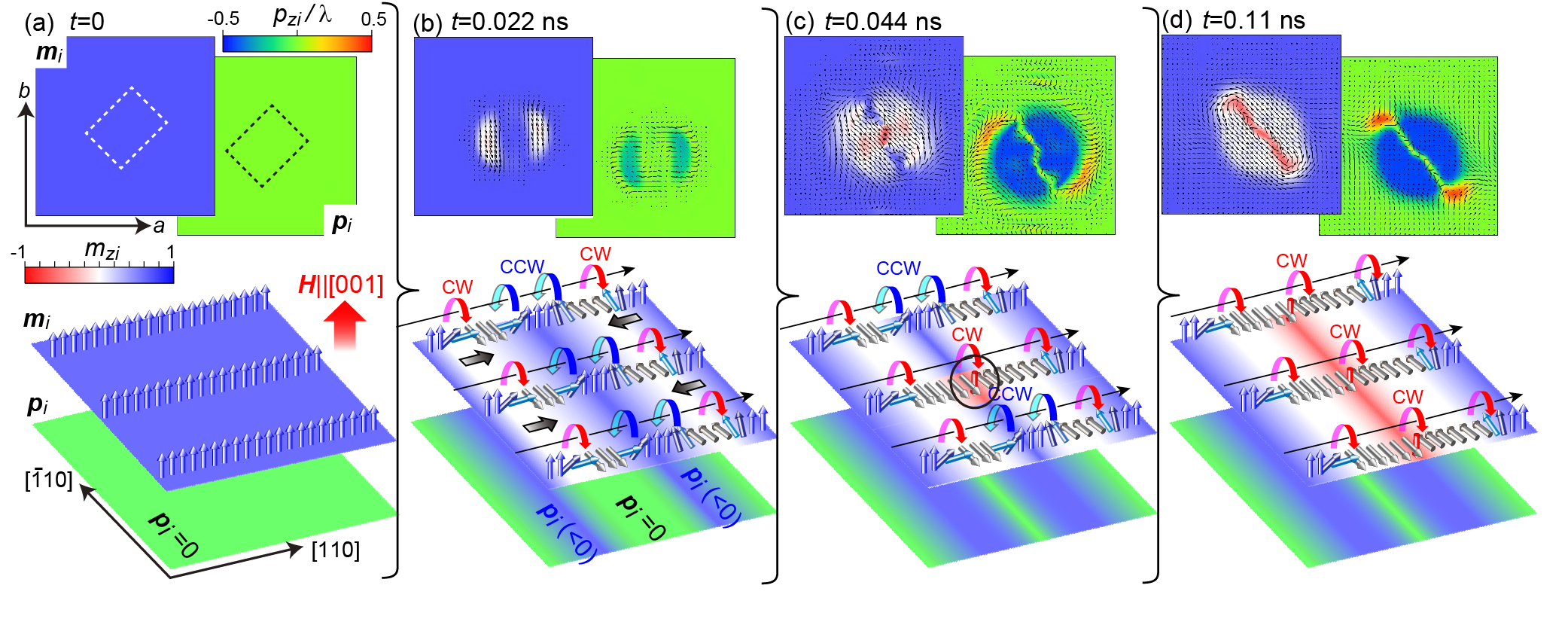
We find that the local reversal of is a key element in the creation of the topological skyrmion texture. Figures 3(a)-(d) show the reversal process induced by the -field; the two upper panels are simulated snapshots of the and distributions, while the two lower panels are schematics of the and alignments in the relevant areas indicated by the dashed lines in Fig. 3(a). Initially, the vectors are uniformly oriented in the [001] direction, and the polarizations are thus uniformly zero [see Fig. 3(a)]. When we apply a negative -field with , the vectors near the periphery of the -field area begin to rotate to point in the in-plane directions ([10] or [10] direction) [see Fig. 3(b)], because the induced by the in-plane-oriented are favorable when . This -rotation occurs in the clockwise (CW) direction around the periphery upon propagation in the [110] direction, indicated by solid arrows, because it is energetically favored by the Dzyaloshinskii-Moriya interactions of Eq. (1) when . This type of reorientation, however, necessarily causes rotating alignments in the counterclockwise (CCW) direction inside the -field area [see Fig. 3(b)], which are energetically unfavorable for the Dzyaloshinskii-Moriya interactions. To resolve this energy cost, the at a specfic site, indicated by the solid circle in Fig. 3(c), flops to be reversed and thus make the rotation sense clockwise. This nucleated -reversed spot immediately grows into a line-shaped area as shown in Fig. 3(d).
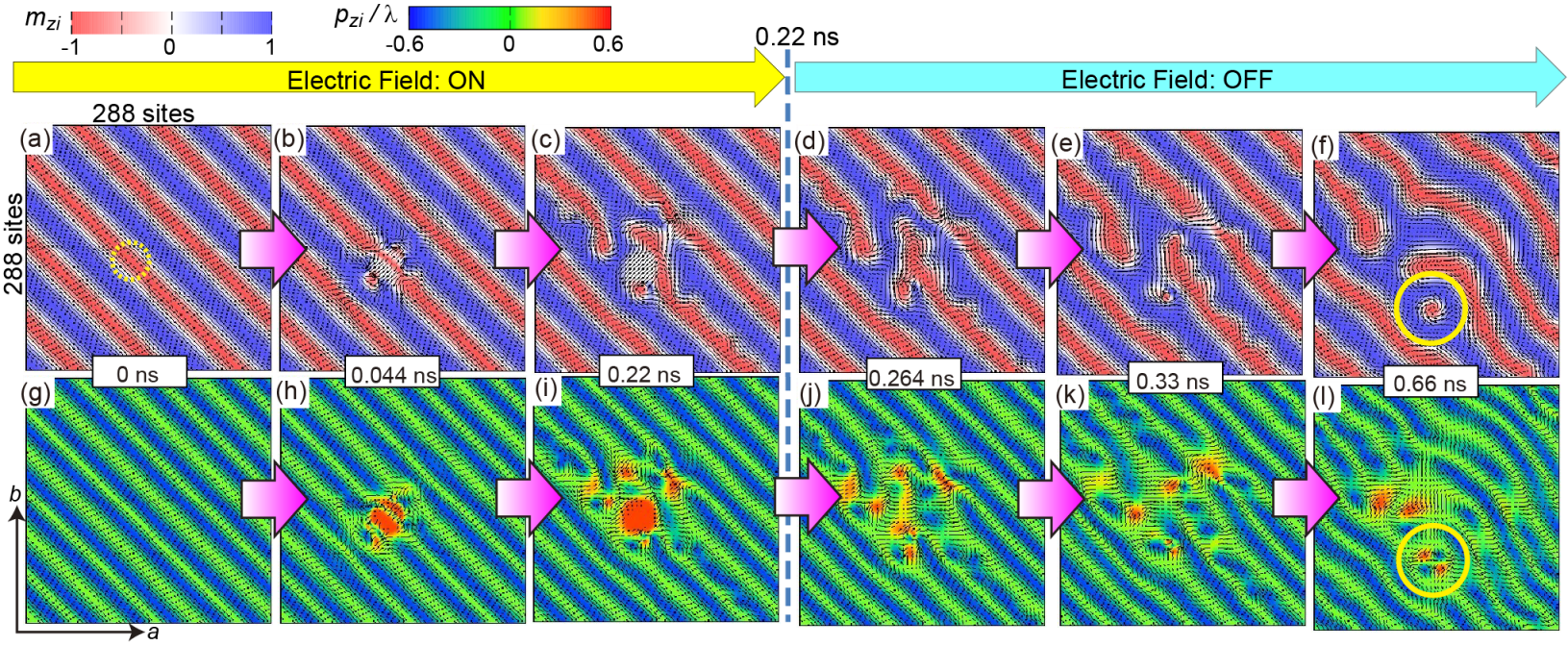
Our simulations demonstrate that an isolated skyrmion can also be created in the helimagnetic state. Figures 4(a)-(l) show snapshots of the and distributions for the simulated dynamical process of electrical skyrmion creation in the helimagnetic state with propagation vector [110]. In this case, we set =486 Oe, V/m, (, )=(288, 288), and sites. We find that the sign of must be chosen appropriately, depending on the vector, to create a skyrmion in the helimagnetic state. The helical vector in a chiral cubic magnet like Cu2OSeO3 tends to be oriented in the [110] or [10] direction on the [001] plane because of the higher-order magnetic anisotropy. We also note that the sign of determines the sign of and subsequently the direction of the in-plane-oriented . A skyrmion can be created when the in-plane-oriented in the -field area is perpendicular to the in-plane components of the helically ordered , or is equivalently parallel to the vector, which efficiently cuts the helimagnetic alignment of to create a skyrmion seed. should therefore be positive (negative) when [110] ([10]).
In summary, we have theoretically demonstrated that by using magnetoelectric coupling in multiferroic chiral magnets, isolated magnetic skyrmions can be created electrically through local electric-field application via an electrode tip on ferromagnetically- or helimagnetically-ordered thin-film samples under [001]. To date the creation of skyrmions in spin-polarized scanning tunneling microscopy has been successfully demonstrated on a metallic sample Romming13 , which indicates that the experimental technique required to realize our proposed method is already established. The proposed method, which is based on an electric field in an insulator, is free from Joule-heating losses and is thus expected to be useful for future spintronics applications of multiferroic skyrmions in high-efficiency magnetic storage devices. While the simulations presented here were all performed at =0, the proposed mechanism is expected to work at finite temperatures below . Also, thermal fluctuations may reduce the threshold -field strength for -reversal by reducing the free-energy barriers. However, of 58 K for Cu2OSeO3 is quite low for real device applications, and further research to identify suitable materials with higher values is needed.
The authors would like to thank A. Rosch and N. Romming for enlightening discussions. This research was in part supported by JSPS KAKENHI (Grant Nos. 25870169 and 25287088).
References
- (1) A. N. Bogdanov and D. A. Yablonskii, Sov. Phys. JETP 68, 101 (1989).
- (2) S. Mühlbauer, B. Binz, F. Jonietz, C. Pfleiderer, A. Rosch, A. Neubauer, R. Georgii, and P. Böni, Science 323, 915 (2009).
- (3) X. Z. Yu, Y. Onose, N. Kanazawa, J. H. Park, J. H. Han, Y. Matsui, N. Nagaosa, and Y. Tokura, Nature (London) 465, 901 (2010).
- (4) F. Jonietz, S. Mühlbauer, C. Pfleiderer, A. Neubauer, W. Munzer, A. Bauer, T. Adams, R. Georgii, P. Böni, R. A. Duine, K. Everschor, M. Garst, and A. Rosch, Science 330, 1648 (2010).
- (5) X. Z. Yu, N. Kanazawa, W. Z. Zhang, T. Nagai, T. Hara, K. Kimoto, Y. Matsui, Y. Onose, and Y. Tokura. Nature Commun. 3, 988 (2012).
- (6) T. Schulz, R. Ritz, A. Bauer, M. Halder, M. Wagner, C. Franz, C. Pfleiderer, K. Everschor, M. Garst, and A. Rosch, Nature Physics 8, 301 (2012).
- (7) K. Everschor, M. Garst, R. A. Duine, and A. Rosch, Phys. Rev. B 84, 064401 (2011).
- (8) J. Zang, M. Mostovoy, J. H. Han, and N. Nagaosa, Phys. Rev. Lett. 107, 136804 (2011).
- (9) J. Iwasaki, M. Mochizuki, and N. Nagaosa, Nature Commun. 4, 1463 (2013).
- (10) J. Iwasaki, M. Mochizuki, and N. Nagaosa, Nature Nanotech. 8, 742 (2013).
- (11) N. Nagaosa, and Y. Tokura, Nature Nanotech. 8, 899 (2013).
- (12) A. Fert, V. Cros, and J. Sampaio, Nature Nanotech. 8, 152 (2013).
- (13) J. Sampaio, V. Cros, S. Rohart, A. Thiaville, and A. Fert, Nature Nanotech. 8, 839 (2013).
- (14) S. Seki, X. Z. Yu, S. Ishiwata, and Y. Tokura, Science 336, 198 (2012).
- (15) T. Adams, A. Chacon, M. Wagner, A. Bauer, G. Brandl, B. Pedersen, H. Berger, P. Lemmens, and C. Pfleiderer, Phys. Rev. Lett. 108, 237204 (2012).
- (16) S. Seki, J.-H. Kim, D. S. Inosov, R. Georgii, B. Keimer, S. Ishiwata, and Y. Tokura, Phys. Rev. B 85, 220406 (2012).
- (17) S. Seki, S. Ishiwata, and Y. Tokura, Phys. Rev. B 86, 060403 (2012).
- (18) J. S. White, I. Levatić, A. A. Omrani, N. Egetenmeyer, K. Prša, I. Živković, J. L. Gavilano, J. Kohlbrecher, M. Bartkowiak, H. Berger, and H. M. Rønnow, J. Phys. Condens. Matter 24, 432201 (2012).
- (19) J. S. White, K. Prša, P. Huang, A. A. Omrani, I. Živković, M. Bartkowiak, H. Berger, A. Magrez, J. L. Gavilano, G. Nagy, J. Zang, and H. M. Rønnow, Phys. Rev. Lett. 113, 107203 (2014).
- (20) Jan-Willem G. Bos, C. V. Colin, and T. T. M. Palstra, Phys. Rev. B 78, 094416 (2008).
- (21) M. Belesi, I. Rousochatzakis, H. C. Wu, H. Berger, I. V. Shvets, F. Mila, and J. P Ansermet, Phys. Rev. B 82, 094422 (2010).
- (22) P. Bak and M. H. Jensen, J. Phys. C 13, L881 (1980).
- (23) S. D. Yi, S. Onoda, N. Nagaosa, and J. H. Han, Phys. Rev. B 80, 054416 (2009).
- (24) S. M. Mohseni, S. R. Sani, J. Persson, T. N. Anh Nguyen, S. Chung, Ye. Pogoryelov, P. K. Muduli, E. Iacocca, A. Eklund, R. K. Dumas, S. Bonetti, A. Deac, M. A. Hoefer, and J. Akerman, Science 339, 1295 (2013).
- (25) N. Romming, C. Hanneken, M. Menzel, J. E. Bickel, B. Wolter, K. von Bergmann, A. Kubetzka, and R. Wiesendanger, Science 341, 636 (2013).