Evolution of the electronic and lattice structure with carrier injection in BiFeO3
Abstract
We report a density functional study on the evolution of the electronic and lattice structure in BiFeO3 with injected electrons and holes. First, the self-trapping of electrons and holes were investigated. We found that the injected electrons tend to be localized on Fe sites due to the local lattice expansion, the on-site Coulomb interaction of Fe electrons, and the antiferromagnetic order in BiFeO3. The injected holes tend to be delocalized if the on-site Coulomb interaction of O is weak (in other words, is small). Single center polarons and multi-center polarons are formed with large and intermediate , respectively. With intermediate , multi-center polarons can be formed. We also studied the lattice distortion with the injection of carriers by assuming the delocalization of these carriers. We found that the ferroelectric off-centering of BiFeO3 increases with the concentration of the electrons injected and decreases with that of the holes injected. It was also found that a structural phase transition from to the non-ferroelectric occurs, with the hole concentration over 8.7. The change of the off-centering is mainly due to the change of the lattice volume. The understanding of the carrier localization mechanism can help to optimize the functionality of ferroelectric diodes and the ferroelectric photovoltage devices, while the understanding of the evolution of the lattice with carriers can help tuning the ferroelectric properties by the carriers in BiFeO3.
pacs:
71.38.Ht, 77.80.-eI Introduction
In transitional metal oxide perovskites, there is strong correlation between the degrees of freedom of charge and lattice. When extra charges are injected into those materials, they interacts with the lattice, causing novel phenomenon. Unlike in the conventional insulators and semiconductors, the change in BiFeO3 (BFO) with injected carriers cannot be seen as a mere rigid shift of the band. The lattice distorts with the carrier injection, and the injected carriers can be trapped due to the lattice distortion. Here we investigate the behaviors of the injected carriers and the lattice in BFO with first principle methods.
BFO has been of great interests for many yearsCatalan and Scott (2009), because its large ferroelectric polarization and relatively small band gapPalai et al. (2008); Gujar et al. (2007); Ihlefeld et al. (2008); Xu and Shen (2008); Clark and Robertson (2007) make it a good choice as semiconductor and optoelectronic materialBasu et al. (2008); Wang et al. (2013) in devices such as ferroelectric diodeChoi et al. (2009); Wang et al. (2011); Ge et al. (2011) and ferroelectric photovoltaic device Yang et al. (2010); Kreisel et al. (2012). In these devices, carriers are injected into BFO either by electric field or optical excitation. A most important issue about the carriers is whether they tend to be localized or delocalized, as this greatly affects the mobility and the lifetime of the carriers and the leakage current in BFO. Therefore, the understanding of the carrier behavior in BFO is crucial for revealing the mechanisms behind its abundant properties, as well as for the development of the devices.
There are a few evidences showing that the carrier has the tendency to be trapped in BFO. The electronic conductivity in non-doped and -type BFO follows the law, implying the polaron hopping mechanismSelbach et al. (2008); Masó and West (2012); Wang and Wang (2009). Hole doping were achieved by substituting Bi or Fe ions with acceptor cations (like Ca2+, Sr2+, Ba2+, Ni2+, and Mg2+) Masó and West (2012); Wang et al. (2006); Yang et al. (2009); Qi et al. (2005).Large concentration of acceptor cations tends to break the symmetry of bulk. For example, by substituting about 10% Bi ions with Ca ions, there is a monoclinic to tetragonal phase transition in BFO thin filmsYang et al. (2009). Whereas it’s difficult to achieve -type doping; substituting Fe ions with Ti4+ or Nb5+ decreases the conductivity in BFO Qi et al. (2005); Jun et al. (2005). In the chemically doped BFO structures, whether the polarons are bounded to dopants or self-trapped is not clear. Schick et al. studied the dynamics of the stress in BFO due to the excited charge carriers with ultrafast X-ray diffraction and found that the carriers tend to be localizedSchick et al. (2014). Yamada et al. found photocarriers can be trapped by means of transient absorption and photocurrent measurementsYamada et al. (2014).The trapping of the carriers can happen because of the defects or the self-trapping effect in BFO. In the latter case, the carriers reduce their energies due to the local lattice distortion and form small polarons. The states of the trapped carriers are in the band gap, thus these carriers need energy to be excited and become conducting. In-gap states were observed in absorption spectra and photoluminescence measurementsXu et al. (2009); Pisarev et al. (2009); Ramirez et al. (2009); Hauser et al. (2008), while whether these states should be attributed to defect states or self-trapped states has not been clear yet. There has been extensive study on the defects states Ederer and Spaldin (2005); Paudel et al. (2012); Zhang et al. (2010), whereas the study into the self-trapped state is lacking. In this work, we firstly investigate the self-trapping of the injected electrons and found that the electrons tend to be localized even when the defects are absent. The localization of injected holes were also studied. We found that the holes tend to be delocalized, to form multi-centered polarons, and to form single centered polarons if the on-site Coulomb interaction of O electrons is weak, intermediate, and strong, respectively. The lattice distortions near the localized electrons/holes were also studied.
Another important issue is that how the lattice deforms if the injection of carriers are delocalized. The injected carriers, which are affected by the lattice, affect the lattice in return, thus can modulate the ferroelectric distortions. In ferroelectrics, the off-centering of ions, which is stabilized by the long-range Coulomb interaction, tend to be unstable with free charge, as the free carriers can screen the Coulomb interaction. However, ferroelectric metal, in which ferroelectric displacement coexists with conducting carriers, was predicted by Anderson and Blount Anderson and Blount (1965) and then identified in LiOsO3Shi et al. (2013). In some ferroelectrics, the ferroelectric displacement can survive within a range of carrier concentration. For example, BaTiO3, another ferroelectric perovskite, undergoes a phase transition from ferroelectric tetragonal phase to cubic with the injection of electrons above a critical concentrationIwazaki et al. (2012); Wang et al. (2012). Can the ferroelectricity of BFO sustain the carrier injection? If it can, how is the ferroelectric displacement tuned by charges? In this work, we also studied the evolution of the lattice structure with the injection of carriers. We found that a structural phase transition from to the non-ferroelectric structure occurs, if the hole concentration is over a criterion of . This indicates that hole injection can be used as an efficient way of depolarization of BFO if holes tend to be delocalized. Whereas the free electrons do not destabilize the ferroelectric distortion, but enhance the structural off-centering of BFO, which supports the idea that long-range ferroelectric order can be driven by short-range interactionsXiang (2014).
II Methods
The density functional theory (DFT) calculations have been performed using the local spin density approximationPerdew and Zunger (1981) (LSDA) and projector augmented wave methodKresse and Joubert (1999) as implement in the Vienna ab initio simulation package (VASP)Kresse and Furthmüller (1996). A plane-wave basis set with the energy cutoff of 450 eV were used to represent the wave functions.
The localization of the carrier depends on whether the localized electronic state can form within the band gap. Therefor a good description of the band gap is needed. Local density approximation (LDA) and generalized gradient approximation (GGA) calculations always underestimate the band gap and tend to fail in predicting the localization of carriers. Our LDA calculation gives a band gap of 0.5 eV while the experimental band gap of BFO is about 2.8 eV. The DFT +U method can improve the description of the electronic properties in BFO Neaton et al. (2005) by adding a Hubbard U Liechtenstein et al. (1995); Dudarev et al. (1998) correction. Goffinet et al. Goffinet et al. (2009) compared the results of DFT+U and hybrid functionals and found that both can describe the structural properties well. The band gap with the hybrid functional B1-WC calculation is 3.0 eV, while the LDA+U calculation with a eV gives a 2.0 eV band gap. We used the more computationally inexpensive LDA+U correction in all our calculations. An effective eV, which can give qualitative and sub-quantitative correct result for the structural, magnetic, and electronic properties in BFO, is used throughout this paper unless otherwise stated. In the calculations of the hole polarons, various ’s ranging from 0 eV to 12 eV were used. Adding Hubbard to O was found to be an effective way for the calculation of the hole polarons in titanite perovskitesErhart et al. (2014), in which the valence band maximum (VBM) is mostly O states.
Bulk BFO adopts the symmetry with space group , which can be viewed as pseudo cubic structure with a ferroelectric polarization along the [111] direction. We constructed , , and pseudo cubic supercells, and by adding/removing one electron from the supercells, the concentration of the electrons/holes in these supercells are 1/4, 1/8, and 1/16 u.c.-1, respectively. The and supercells are constructed from the structure in phase. The structures in phase and phase are very close. If the structure of the two phases are both put in supercells, the only difference between them would be that the angles ( and ) of the lattice parameters for the phase are all about 89.9∘, while and are fixed to 90∘ in the phase. The localized electrons/holes break the symmetry of the bulk. Here, a -centered k-point grid were used to integrate the Brillouin Zone. G-type antiferromagnetic structure was assumed in all the calculations. The image charge correctionMakov and Payne (1995) and the potential-alignment correctionLany and Zunger (2008) were utilized in the DFT calculations with the adding and removing of the electrons.
To find whether the electron injected into the BFO is delocalized or localized, we compared the two states with and without the bulk symmetry being broken. By following the recipes of Deskins et al. Deskins et al. (2011),we first elongate the Fe-O bonds around one Fe site to break the transition symmetry. Then we set the initial magnetic moment of the specific Fe site 1 less than those of the other Fe sites, since Fe3+ ion has the high spin electronic configuration, adding one electron will reduce the net magnetic moment. By using this as the initial state and relaxing the structure, the localized polaronic state can be obtained if there is a localized state within the band gap of BFO. Similar method can be applied in the calculation related to the hole localization. The initial structures were constructed by stretching or compressing the bonds near the hole center. In BFO without injected holes, O states are almost fully occupied, thus have 0 spin. An 1 magnetization was set as the initial value for the O ion where the hole is assumed to be localized.
To see how the lattice distorts with the carrier concentration, the symmetries of the lattices are fixed to a few low energy phases, namely the , , , , and , respectively. A -centered k-point mesh was used with these calculations.
III Results and Discussion
III.1 Bulk properties
Here we look into the bulk properties of BFO. The primitive cell of BFO with symmetry is shown in the inset of Fig. 1. There are 10 atoms in the primitive cell, including two 2 Bi atoms, 2 Fe atoms, and 6 O atoms. Each Bi atom has 12 neighboring O atoms; each Fe atom has 6 neighboring O atoms which make an octahedron. The calculated structural parameters with various ’s are given in table 1, which agree well with experimental dataKubel and Schmid (1990) and previous calculations(e.g. in Ref. (38)).
The partial density of states of BFO is in Fig. 1. The states at the conduction band minimum (CBM) are mostly the Fe states. Consequently, the injected electrons mainly stay at the Fe sites. The valence band maximum (VBM) consists of O , Fe , and Bi states. Though the Bi states are deep below the Fermi energy, the strong hybridization between the Bi 6s and O 2p orbitals lead to considerable Bi DOS at the VBM. The electron lone pair, which is the driving force of the ferroelectricity in BFO, is related to the Bi 6s-O antibonding states at the VBM Ravindran et al. (2006). Which site are the injected holes localized (if they tend to be localized) at needs to be investigated.

.
| (, ) | (4, 0)111Result from LDA+U calculation, this work. | (4, 0)222Result from LDA+U calculation, Ref. (38). | (4, 8)1 | (4, 12)1 | Exp333Experimental result, Ref. (46). | |
|---|---|---|---|---|---|---|
| Bi (2a) | 0 | 0 | 0 | 0 | 0 | |
| Fe (2a) | 0.226 | 0.227 | 0.227 | 0.227 | 0.221 | |
| O (6b) | 0.540 | 0.542 | 0.538 | 0.536 | 0.538 | |
| 0.942 | 0.943 | 0.942 | 0.940 | 0.933 | ||
| 0.397 | 0.397 | 0.398 | 0.399 | 0.395 | ||
| (Å) | 5.52 | 5.52 | 5.49 | 5.47 | 5.63 | |
| (deg) | 59.79 | 59.84 | 59.82 | 59.72 | 59.35 |
III.2 Self trapping of electrons
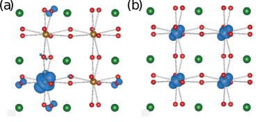
Electrons injected into the BFO lattice can be either delocalized or localized, depending on how they interacts with the lattice. The delocalized electrons stay on the CBM and the symmetry of the lattice is preserved. Whereas the localized electrons break the symmetry of the lattice, and change the local chemical bonds to lower the energy, forming an in-gap state, i.e. forming a small polaron. To understand the behavior of the injected electrons, we compared the two kinds of electron states with the DFT+ calculations. Figures 2 (a) and (b) show the electron density isosurfaces for the localized and the delocalized state, respectively. The localized electron resides mostly on one Fe site and the delocalized electron distributes on all Fe sites.
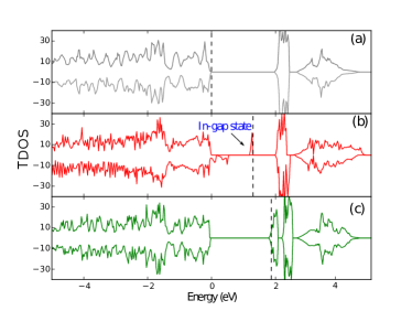
To see whether the in-gap state is stable, we calculated the electronic structures of the BFO with localized and delocalized injected electron. The total density of states (TDOS) of the supercell are shown in Fig. 3. The TDOS of BFO without injected electrons is used as a reference. In the localized case, there is a in-gap state of about 0.6 eV below the CBM, which corresponds to the localized electron state. The in-gap state are 0.5 and 0.7 eV below the CBM in the supercells with electron concentration of 1/4 and 1/16 u.c.-1, respectively. As for the delocalized state, the change is not just a Fermi energy shift within rigid bands, either. A split in the formerly unoccupied Fe band can be clearly seen. The possible reasons are the change in the lattice and the electron-electron interaction, which shift the occupied bands down and unoccupied bands up.
The electron self-trapping energy defined as
where is the total energy of BFO cell with an injected electron at the CBM, is the total energy of the BFO with a localized electron. A positive value means that the small polaronic state is energetically preferable. The of the supercells with electron concentration of 1/4, 1/8, and 1/16 u.c.-1 are 0.66, 0.50, and 0.39 eV, respectively.
We analyzed the possible mechanism for the self-trapping of electrons, and found that the self-trapping is driven by the local lattice expansion and the Coulomb repulsion of the Fe 3 electrons, and is stabilized by the antiferromagnetic structure.

One reason for the self-trapping of electrons is the distortion of the lattice surrounding the electrons. The most obvious change of the lattice is the expansion of the Fe-O octahedra where the injected electrons are localized. In the ferroelectric BFO, the six Fe-O bonds of each Fe ion can be divided into two groups, the group of longer bonds and the group of shorter bonds, as the Fe atoms do not reside at the center of the oxygen octahedra. We found both groups of Fe-O bonds near the injected electrons are elongated as listed in table 2. The elongation of the bonds can be easily understood as the consequences of the Coulomb repulsion between the injected electron and the negatively charged oxygen ions. Because of elongation of the Fe-O bonds, the Coulomb energy of the injected electrons is reduced. Meanwhile, this elongation reduces the Fe -O overlap, suppressing the hopping of the injected electrons and increasing the tendency of localization.
The higher the carrier concentration is, the larger the elongation is, as the elongation of the Fe-O bonds rises the elastic energy of the surrounding lattices. The difference of the energy between the localized state and the CBM is larger in the structure with higher electron concentration, which is consistent with the longer local Fe-O bonds as shown in Table 2. On the other hand, the EEST is smaller in the structure with lower electron concentration because of the increasing of the elastic energy cost.
| electron concentration | ||||
|---|---|---|---|---|
| no injection | - | - | 2.05 | 1.94 |
| 1/16 /u.c. | 2.11 | 2.01 | 2.05 | 1.93 |
| 1/8 /u.c. | 2.12 | 2.01 | 2.07 | 1.94 |
| 1/4 /u.c. | 2.15 | 2.04 | 2.11 | 1.94 |
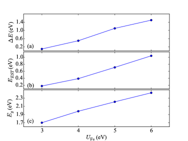
Another reason for the self-trapping of the electrons is the Coulomb repulsion effect of the electrons. To see how this influences the localization of the electrons, we calculated the electronic structure with various effective ’s ranging from 0 to 6 eV. The self-trapping happens only if 2 eV. We found the difference between the energy of the in-gap state and that of the lowest unoccupied state is larger with larger , as shown in Fig. 5 (a). The in-gap state and the lowest unoccupied state are both Fe , thus the former can be seen as the lower Hubbard band (LHB) and the later as the upper Hubbard band (UHB). The on-site Coulomb repulsion of the Fe electrons shift the LHB down and the UHB up, enlarging the difference between them. Because the Coulomb repulsion lowers the energy of the localized electron, the self-trapping of the electrons are stabilized. Therefore, the self-trapping energy is higher with larger , as shown in Fig. 5 (b).
In all the structures, our calculations gave the results of G-type antiferromagnetic order with a total magnetic moment of 1 when one electron is self-trapped. The projected density of states of Fe orbitals are shown in Fig. 4. The in-gap state has the opposite spin with the other occupied states on the same site. Therefore, the electronic configurations of the Fe ions are and with and without the localized electron, respectively (Figs. 4 (a) and (b)). In the Fe sites neighboring to that with localized electron, the five states with the same spin as the in-gap state are fully occupied, which makes the hopping to the nearest neighbors forbidden. Therefore, the antiferromagnetic order stabilize the localization of the injected electron.
III.3 Self trapping of holes
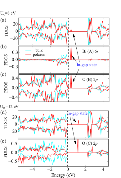
The self-trapping of holes was also investigated. In BFO, the top of the valence band is a mix of O , the Fe and Bi states, as shown in Fig. 1. Therefore, we need to know what sites would the polarons reside on if the holes are self-trapped. We found that Fe-site centered small polaron is energetically unfavorable with a large range of from 0 eV to 8 eV. The largest contribution to the top of valence band is from the O states. We explored the self-trapping of holes by adding Hubbard to the O states Erhart et al. (2014). Using various from 0 to 12 eV, we found that holes tend to be delocalized with 6 eV; small polarons centered on O sites are stabilized for 12 eV; multicenter polarons are formed if is between 6 eV and 12 eV. The delocalized holes, multi-center polaron, and the single-center small polaron are shown in Fig. 6 (a), (b), and (c), respectively. The delocalized hole mainly distributes uniformly at the O sites; the multi-center hole polaron stays on the hybridized orbital of Bi and O (mainly at three O sites and the Bi site near their center); the single center hole polaron mainly stays at one O site. The TDOS calculated with =8 eV and =12 eV are in Fig. 7 (a) and (d), respectively. States inside the band gap of the structure emerges, which corresponds to the polarons.

The change of the band gap () with is small since the O bands are almost fully filled in bulk BFO (Fig. 8 (c)). Adding to the O state does not significantly improve the lattice structure results, as can be seen from table 1. Therefore, we do not intend to acclaim what value of is most appropriate for describing the self-trapping of the holes. Thus we also don’t acclaim whether and what kind of hole polarons tend to be formed here. Instead, we study the properties of the polarons by varying the .
Like the self-trapping of electrons, the self-trapping of holes is also stabilized by on-site electron Coulomb interaction. Since most of the hole states are O , the dependence on is not significant. We studied the dependence of the self-trapping energy and the in-gap state energy on . The hole self-trapping energy defined as
where is the total energy of BFO supercell with an injected hole at the VBM, is the total energy of the BFO supercell with a hole polaron. The dependence of the was studied. The increases with , as shown in Fig. 8 (b). In BFO without carrier injection, the O states are almost fully occupied. With the removing of one electron, the in-gap state and the occupied O states can be seen as the UHB and LHB of the O , respectively. The effect of is to push the in-gap state (the UHB) up and the occupied O 2p states (the LHB) down, which lowers the total energy. Figure 8 (a) shows that the energy difference () between the in-gap state and the VBM increases with , which is consistent with the larger UHB/LHB splitting.

The multi-center hole polaron state is a mix of Bi and O state, indicating that the hybridization between them is strong and plays an important role. The PDOSes of Bi and O on the sites corresponding to the ions marked as A and B in Fig. 6 (b) are shown in Fig. 7 (b) and (c). It can be seen that both the Bi and O state components are in the in-gap state. Instead of pushing one O orbital up into the band gap, the Hubbard on O pushes the hybridized (Bi , O ) state up. The delocalization effect of the hybridization competes with the localization effect of the on-site electron Coulomb interaction. With small (6 eV), the delocalization is predominant, leading to free holes. With large (12 eV), the localization becomes predominant, leading to single-center small polarons. With intermediate , multi-center polarons are formed.
Here we look into the local lattice distortion near the multi-center polaron. The multi-center polaron does not break the 3-fold rotation symmetry. The rotation axis is along [111] and through the Bi ion marked as A in Fig. 6 (b). The lengths of the bonds between this Bi ion and O ions decreases as the polaron is formed (Fig. 6 (c)). Since the Bi and O states are antibonding at the top of valence band, the decreasing of the Bi-O bond length enhance the Bi - O hybridization and further pushes the unoccupied anti-bonding state up. Consequently, the in-gap state is stabilized by the lattice distortion. The change to the lengths of Fe-O bonds is relatively small (Fig. 6 (e)).
The single-center hole polaron is mostly on one O orbital as shown by the spatial distribution of the hole (Fig. 6 (c)) and the PDOS (Fig. 7 (e)). For the single-center polaron state, the on-site energy play a more important role than the inter-site orbital hybridization. The lengths of the Bi-O bonds and Fe-O bonds for the O site where the hole is localized increase (Figs. 6 (g) and (h)), i.e. the distances between the hole and the positively charged ions increase. Thus the Coulomb energy is reduced, which stabilizes the self-trapping of holes on the O site.
III.4 Lattice deformation with delocalized carriers
Here we investigate the distortion of the lattice under the assumption that the injected carriers are delocalized. We calculated the total energy of various structural arrangements (, , , , ) with the change of concentration of delocalized carriers. The structure of the phase is very close to the structure. Therefore, the energy difference between the and phase is almost zero and we do not distinguish these two phases here. The is the paraelectric phase of BFO at high temperature. The phase is featured with antiferroelectric oxygen octahedron rotations, which compete with the ferroelectric distortion. In the stucture, the antiferroelectric oxygen octahedron rotations coexist with Bi ion off-centering displacements. The results are shown in Fig. 9. The structure is energetically preferable with electron injection. For hole concentration larger than 0.005 hole per BFO unit (about 8.7), the orthorhombic structure, which is not ferroelectric, is energetically preferable. Therefore, BFO of tends to be depolarized with hole injection. The estimated value of the critical hole concentration is quite rough, as the energy difference between the phases near the phase transition point is small. It also depends on the functional used. The Perdew-Burke-Ernzerhof Perdew et al. (1996) (PBE) functional plus with gives a concentration of about 0.08 u.c.-1 (about cm-3). But the trend toward the phase transition is robust. Neither 0.005 nor 0.08 holes per unit cell is a too large number, which indicates that hole injection can be an efficient way to depolarize the BFO if the holes are delocalized.

The details of the evolution of the lattice structure with the symmetry kept are shown in Fig. 10. The volume of the lattice increases with electron injection, and decreases with hole injection, as shown in Fig. 10 (a). The absolute positions of the band edges shift in order to minimize the electronic energy, which is achieved by changing the volume. The ferroelectric off-centering of BFO has two main features, one being that the Fe site with Wyckoff position deviates from the centrosymmetric position , the other being that Fe-O bonds form two groups of longer and shorter bonds. The Wyckoff positions of Fe and the lengths of Fe-O bonds are shown in Fig. 10 (b) and (c), respectively. The off-centering is stronger as the concentration of the injected electrons increases. The trends are opposite with the injection of holes into the BFO structure. In summary, the injection of depolarized electrons enhances the off-centering of the , whereas that of the holes reduces the off-centering.

The change of the lattice structure with concentration of carriers is very much alike to the change with the hydrostatic strain. A to transition with a hydrostatic pressure were predicted and foundRavindran et al. (2006); Haumont et al. (2009). Diéguez et al.Diéguez et al. (2011) proposed that the reduction in structural off-centering and the phase transition are because of the less directional Bi-O bonds caused by the decreasing of the lattice volume. Just like in the hydrostatic compressed structures, the volume of the unit cell, the off-centering of the Fe cations, and the difference in the short and long Fe-O bonds are reduced in the hole injected structure, as shown in Fig. 10.
Because of the similarity in the structural evolutions with carrier injection and hydrostatic pressure, the two kinds of evolutions can have the same origin. The reason for the weakening of the structural off-centering can be that the Bi-O bonds are less directional with the shrinking of the volume with the hole injection.

To see whether above speculation is true or not, we analyzed the Bi-O bonds in BFO. With the electronic configuration of Bi3+ ion being , Bi ions can shift away from the central symmetric positions, forming Bi-O bonds on one side of Bi atoms and the lone pairs on the other side of Bi atomsRavindran et al. (2006). The forming of the lone pairs costs energy, while the forming of Bi-O covalent bondings gains energy. Therefore, if the Bi-O covalent bonding is strong enough, the forming of lone pairs and directional Bi-O bonds is stabilized, leading to the structural off-centering in BFO. In the structure with ferroelectric polarization in the [111] direction, Bi ions has 12 O neighbors. Because of the 3 fold rotation symmetry, these bonds can be divided into 4 groups labeled as I, II, III, and IV, as shown in Fig. 11 (a). The Bi-O bonds on the [111] direction side (group I) are shorter than those on the opposite side (group IV), leading to the Bi lone pair on the opposite to the polarization in BFO, which can be seen from the electron localization functionBecke and Edgecombe (1990) in Fig. 11 (b). We compared the evolution of the Bi-O bond lengths with carrier concentration shown in Fig. 11 (c) to that with hydrostatic pressure in Fig. 11 (d), and found almost identical evolution patterns. The difference between the Bi-O bond lengths of group I and IV reduces with hole injection, which is the same with the hydrostatic pressure. Therefore, we can reach the conclusion that the hole injection leads to the reduction in volume and causes less directional Bi-O bonds and the weaker Bi lone pairs. Thus the structural off-centering is reduced. In the non-ferroelectric structure, the Bi-O bonds are less directional, which is compatible with the suppressing of the lone pair. Therefore, the non-ferroelectric phase is favored over the Phase.
The enhancement the structural off-centering with electron injection suggests that the screening of the long-range Coulomb interaction does not necessarily kill the the off-centering. This supports the idea that ferroelectric long-range order can be driven by short-range interactionsXiang (2014). In the case of BFO, this short-range interaction is the cooperative shift of the Bi cations driven by the formation of lone pairs, which is not impaired by the screening of long-range Coulomb interaction. On the contrary, the free electrons on the CBM (mostly Fe bands) pushes the surrounding oxygen anions away, reducing the lengths of the Bi-O bonds labeled as I. Thus the lone pair and the structural off-centering are strengthened.
IV Conclusion
In summary, we studied the electronic and lattice structure evolution of BFO with various concentrations of injected electrons and holes. We found that the electrons tend to be localized, which is stabilize by the electron-electron Coulomb repulsion and the expansion of the oxygen octahedron near the Fe site where the electron resides. The antiferromagnetic order also stabilize the localization. The injected holes tend to be delocalized if the O on-site Coulomb interaction is weak (in other words, is small). Small polarons are formed on O sites if is large. With intermediate , multi-center polarons can be formed. The forming of hole polarons is also stabilized by the lattice distortion.
In the structure with injected carriers, delocalized electrons tend to enhance the off-centering, indicating that the ferroelectricity in BFO is not driven by long-range Coulomb interaction but the cooperative shift of Bi ions. Whereas holes tend to reduce the off-centering. With the hole concentration larger than , there is a phase transition from structure to the non-ferroelectric structure. The reduction of off-centering and the phase transition in BFO are due to the shrinking of the lattice. These results indicate that the carrier injection can be an efficient way to control the ferroelectric distortion if the holes tend to be delocalized.
Acknowledgements.
The work was supported by the National Basic Research Program of China (Grant Nos. 2014CB921001 and 2012CB921403), the National Natural Science Foundation of China (Grant Nos. 11474349, 11574365, and 11404380), and the Strategic Priority Research Program (B) of the Chinese Academy of Sciences (Grant No. XDB07030200).References
- Catalan and Scott (2009) G. Catalan and J. F. Scott, Adv. Matter. 21, 2463 (2009).
- Palai et al. (2008) R. Palai, R. S. Katiyar, H. Schmid, P. Tissot, S. J. Clark, J. Robertson, S. A. T. Redfern, G. Catalan, and J. F. Scott, Phys. Rev. B 77, 014110 (2008).
- Gujar et al. (2007) T. Gujar, V. Shinde, and C. Lokhande, Materials Chemistry and Physics 103, 142 (2007).
- Ihlefeld et al. (2008) J. F. Ihlefeld, N. J. Podraza, Z. K. Liu, R. C. Rai, X. Xu, T. Heeg, Y. B. Chen, J. Li, R. W. Collins, J. L. Musfeldt, X. Q. Pan, J. Schubert, R. Ramesh, and D. G. Schlom, Appl. Phys. Lett. 92, 142908 (2008).
- Xu and Shen (2008) Y. Xu and M. Shen, Materials Letters 62, 3600 (2008).
- Clark and Robertson (2007) S. J. Clark and J. Robertson, Appl. Phys. Lett. 90, 132903 (2007).
- Basu et al. (2008) S. Basu, L. Martin, Y. Chu, M. Gajek, R. Ramesh, R. Rai, X. Xu, and J. Musfeldt, Appl. Phys. Lett. 92, 091905 (2008).
- Wang et al. (2013) L. Wang, K. Jin, C. Ge, C. Wang, H. Guo, H. Lu, and G. Yang, Appl. Phys. Lett. 102, 252907 (2013).
- Choi et al. (2009) T. Choi, S. Lee, Y. Choi, V. Kiryukhin, and S.-W. Cheong, Science 324, 63 (2009).
- Wang et al. (2011) C. Wang, K. Jin, Z. Xu, L. Wang, C. Ge, H. Lu, H. Guo, M. He, and G. Yang, Appl. Phys. Lett. 98, 192901 (2011).
- Ge et al. (2011) C. Ge, K. Jin, C. Wang, H. Lu, C. Wang, and G. Yang, Appl. Phys. Lett. 99, 063509 (2011).
- Yang et al. (2010) S. Yang, J. Seidel, S. Byrnes, P. Shafer, C.-H. Yang, M. Rossell, P. Yu, Y.-H. Chu, J. Scott, J. Ager, et al., Nat. Nanotechnol. 5, 143 (2010).
- Kreisel et al. (2012) J. Kreisel, M. Alexe, and P. A. Thomas, Nat. Mater. 11, 260 (2012).
- Selbach et al. (2008) S. M. Selbach, T. Tybell, M.-A. Einarsrud, and T. Grande, Advanced Materials 20, 3692 (2008).
- Masó and West (2012) N. Masó and A. R. West, Chem. Mater. 24, 2127 (2012).
- Wang and Wang (2009) Y. Wang and J. Wang, J. Phys. D: Appl. Phys. 42, 162001 (2009).
- Wang et al. (2006) D. Wang, W. Goh, M. Ning, and C. Ong, Appl. Phys. Lett. 88, 2907 (2006).
- Yang et al. (2009) C.-H. Yang, J. Seidel, S. Kim, P. Rossen, P. Yu, M. Gajek, Y.-H. Chu, L. W. Martin, M. Holcomb, Q. He, et al., Nat. Mater. 8, 485 (2009).
- Qi et al. (2005) X. Qi, J. Dho, R. Tomov, M. G. Blamire, and J. L. MacManus-Driscoll, Appl. Phys. Lett. 86, 062903 (2005), 10.1063/1.1862336.
- Jun et al. (2005) Y.-K. Jun, W.-T. Moon, C.-M. Chang, H.-S. Kim, H. S. Ryu, J. W. Kim, K. H. Kim, and S.-H. Hong, Solid State Commun. 135, 133 (2005).
- Schick et al. (2014) D. Schick, M. Herzog, H. Wen, P. Chen, C. Adamo, P. Gaal, D. G. Schlom, P. G. Evans, Y. Li, and M. Bargheer, Phys. Rev. Lett. 112, 097602 (2014).
- Yamada et al. (2014) Y. Yamada, T. Nakamura, S. Yasui, H. Funakubo, and Y. Kanemitsu, Phys. Rev. B 89, 035133 (2014).
- Xu et al. (2009) X. S. Xu, T. V. Brinzari, S. Lee, Y. H. Chu, L. W. Martin, A. Kumar, S. McGill, R. C. Rai, R. Ramesh, V. Gopalan, S. W. Cheong, and J. L. Musfeldt, Phys. Rev. B 79, 134425 (2009).
- Pisarev et al. (2009) R. Pisarev, A. Moskvin, A. Kalashnikova, and T. Rasing, Phys. Rev. B 79, 235128 (2009).
- Ramirez et al. (2009) M. O. Ramirez, A. Kumar, S. A. Denev, N. J. Podraza, X. S. Xu, R. C. Rai, Y. H. Chu, J. Seidel, L. W. Martin, S.-Y. Yang, E. Saiz, J. F. Ihlefeld, S. Lee, J. Klug, S. W. Cheong, M. J. Bedzyk, O. Auciello, D. G. Schlom, R. Ramesh, J. Orenstein, J. L. Musfeldt, and V. Gopalan, Phys. Rev. B 79, 224106 (2009).
- Hauser et al. (2008) A. Hauser, J. Zhang, L. Mier, R. Ricciardo, P. Woodward, T. Gustafson, L. Brillson, and F. Yang, Appl. Phys. Lett. 92, 2901 (2008).
- Ederer and Spaldin (2005) C. Ederer and N. A. Spaldin, Phys. Rev. B 71, 224103 (2005).
- Paudel et al. (2012) T. R. Paudel, S. S. Jaswal, and E. Y. Tsymbal, Phys. Rev. B 85, 104409 (2012).
- Zhang et al. (2010) Z. Zhang, P. Wu, L. Chen, and J. Wang, Appl. Phys. Lett. 96, 2906 (2010).
- Anderson and Blount (1965) P. W. Anderson and E. I. Blount, Phys. Rev. Lett. 14, 217 (1965).
- Shi et al. (2013) Y. Shi, Y. Guo, X. Wang, A. J. Princep, D. Khalyavin, P. Manuel, Y. Michiue, A. Sato, K. Tsuda, S. Yu, et al., Nat. Mater. 12, 1024 (2013).
- Iwazaki et al. (2012) Y. Iwazaki, T. Suzuki, Y. Mizuno, and S. Tsuneyuki, Phys. Rev. B 86, 214103 (2012).
- Wang et al. (2012) Y. Wang, X. Liu, J. D. Burton, S. S. Jaswal, and E. Y. Tsymbal, Phys. Rev. Lett. 109, 247601 (2012).
- Xiang (2014) H. J. Xiang, Phys. Rev. B 90, 094108 (2014).
- Perdew and Zunger (1981) J. P. Perdew and A. Zunger, Phys. Rev. B 23, 5048 (1981).
- Kresse and Joubert (1999) G. Kresse and D. Joubert, Phys. Rev. B 59, 1758 (1999).
- Kresse and Furthmüller (1996) G. Kresse and J. Furthmüller, Phys. Rev. B 54, 11169 (1996).
- Neaton et al. (2005) J. B. Neaton, C. Ederer, U. V. Waghmare, N. A. Spaldin, and K. M. Rabe, Phys. Rev. B 71, 014113 (2005).
- Liechtenstein et al. (1995) A. Liechtenstein, V. Anisimov, and J. Zaanen, Phys. Rev. B 52, R5467 (1995).
- Dudarev et al. (1998) S. L. Dudarev, G. A. Botton, S. Y. Savrasov, C. J. Humphreys, and A. P. Sutton, Phys. Rev. B 57, 1505 (1998).
- Goffinet et al. (2009) M. Goffinet, P. Hermet, D. Bilc, and P. Ghosez, Phys. Rev. B 79, 014403 (2009).
- Erhart et al. (2014) P. Erhart, A. Klein, D. Åberg, and B. Sadigh, Phys. Rev. B 90, 035204 (2014).
- Makov and Payne (1995) G. Makov and M. C. Payne, Phys. Rev. B 51, 4014 (1995).
- Lany and Zunger (2008) S. Lany and A. Zunger, Phys. Rev. B 78, 235104 (2008).
- Deskins et al. (2011) N. A. Deskins, R. Rousseau, and M. Dupuis, J. Phys. Chem. C 115, 7562 (2011).
- Kubel and Schmid (1990) F. Kubel and H. Schmid, Acta Crystallographica Section B 46, 698 (1990).
- Ravindran et al. (2006) P. Ravindran, R. Vidya, A. Kjekshus, H. Fjellvåg, and O. Eriksson, Phys. Rev. B 74, 224412 (2006).
- Perdew et al. (1996) J. P. Perdew, K. Burke, and M. Ernzerhof, Phys. Rev. Lett. 77, 3865 (1996).
- Haumont et al. (2009) R. Haumont, P. Bouvier, A. Pashkin, K. Rabia, S. Frank, B. Dkhil, W. A. Crichton, C. A. Kuntscher, and J. Kreisel, Phys. Rev. B 79, 184110 (2009).
- Diéguez et al. (2011) O. Diéguez, O. E. González-Vázquez, J. C. Wojdeł, and J. Íñiguez, Phys. Rev. B 83, 094105 (2011).
- Becke and Edgecombe (1990) A. D. Becke and K. E. Edgecombe, The Journal of Chemical Physics 92, 5397 (1990).