Upstream Polling Protocols for Flow Control in PON/xDSL Hybrid Access Networks
Abstract
In a hybrid PON/xDSL access network, multiple Customer Premise Equipment (CPE) nodes connect over individual Digital Subscriber Lines (DSLs) to a drop-point device. The drop-point device, which is typically reverse powered from the customer, is co-located with an Optical Network Unit (ONU) of the Passive Optical Network (PON). We demonstrate that the drop-point experiences very high buffer occupancies when no flow control or standard Ethernet PAUSE frame flow control is employed. In order to reduce the buffer occupancies in the drop-point, we introduce two gated flow control protocols that extend the polling-based PON medium access control to the DSL segments between the CPEs and the ONUs. We analyze the timing of the gated flow control mechanisms to specify the latest possible time instant when CPEs can start the DSL upstream transmissions so that the ONU can forward the upstream transmissions at the full PON upstream transmission bit rate. Through extensive simulations for a wide range of bursty traffic models, we find that the gated flow control mechanisms, specifically, the ONU and CPE grant sizing policies, enable effective control of the maximum drop-point buffer occupancies.
Index Terms:
Buffer occupancy, Digital Subscriber Line (DSL), Flow control, Medium access control, Optical Network Unit (ONU), Passive Optical Network (PON), Polling protocol.I Introduction
Access networks are communication networks that interconnect private local area networks, such as the networks in the homes of individuals, with public metropolitan and core networks, such as those constructed by service providers to connect paying subscribers to the Internet. Private local area networks often employ high speed wired and wireless communications technologies, such as IEEE 802.3 Ethernet (up to 1 Gbit/sec) and IEEE 802.11 WiFi (up to 600 Mbit/sec). These high-speed communications technologies are cost effective in private local area networks due to the short distances involved and subsequent low installation costs. Public metropolitan and core networks employ a variety of communication technologies that include dense wavelength division multiplexed technologies over fiber optic transmission channels (up to 1 Tbit/sec). These high-speed communication technologies are cost effective due to the cost sharing over many paying subscribers. Access networks require significantly higher installation costs compared to private local area networks due to larger distances that must be covered. At the same time, access networks have significantly smaller degrees of cost sharing compared to public metropolitan and core networks; thereby increasing cost per paying subscriber. As a result, access network technologies must keep installation costs low [1]. Utilizing existing bandwidth-limited copper wire or shared optical fiber will keep installation costs low [2].
In this paper we present our study of hybrid access networks that utilize both copper wire and shared optical fiber. The shared optical fiber extends from the service provider’s central office to a drop-point whereby the final few hundred meters to the subscriber premise are reached by existing twisted-pair copper wire. Figure 1 illustrates this hybrid access network architecture that leverages the installation cost benefits of existing copper wire and the latest advances in digital subscriber line (DSL) [3] technology that can realize up to 1 Gbps over short distances of twisted-pair copper wire.
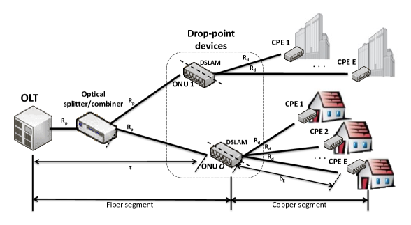
The optical fiber segment of this hybrid access network is organized as a shared passive optical network (PON), whereby multiple optical network units (ONUs) share a single optical fiber connected to an optical line terminal (OLT) at the service provider central office. The copper segments begin at each ONU whereby the fiber is dropped and existing copper wires are utilized via DSL transmission technology to reach each subscriber premise. Each ONU is coupled with a DSL access multiplexer (DSLAM) at the fiber drop-point. This so-called drop-point device is active and therefore requires electric power to operate. However, service providers want these devices to maintain the deploy-anywhere property of the optical splitter/combiner in a typical PON. To maintain this property, each drop-point device is reverse powered using a subscriber’s power source. For this reason, it is of critical importance to reduce the energy consumption of this device.
Reducing the memory capacity of the drop-point is an option for reducing its energy consumption. A drop-point with a small memory capacity translates into a design with a smaller memory device that contains fewer transistors and capacitors that consume energy. However, reducing the memory capacity of a drop-point can result in significant packet loss if measures are not taken to back-pressure the buffering into either the OLT in the downstream direction, or the DSL customer premise equipment (CPE) in the upstream direction. The magnitude of buffering that can occur at the drop-point is quite large due to the transmission bit rate mismatch between the DSL line and the PON. Flow control mechanisms are, therefore, required to avoid significant packet loss. In this paper we specifically examine several upstream polling strategies for controlling the flow of upstream data from each CPE to its associated drop-point device [4]. The objective of these strategies is to minimize the maximum buffer occupancy required at each drop-point with very low or no packet loss.
I-A Background
Providing digital data communication through the access network emerged with Digital Subscriber Loop or Line (DSL) technology in the late 1970s and early 1980s [5]. At that time, researchers identified mechanisms to aggregate digital data signals with analog telephony signals and identified effective power levels and coding mechanisms to tolerate the transmission impairments of the copper loops used for analog telephony. These impairments included signal reflections, cross-talk, and impulse noise [5]. Recent efforts exploit multiple-input-multiple-output (MIMO) or vectoring techniques to cancel the crosstalk impairment [6, 7]. Systems using these techniques can achieve approximately 1 Gbps transmission using four twisted pairs across distances up to 300 meters [7]. The recently developed G.fast [8, 9] DSL standard utilizes vectoring techniques to achieve up to 1 Gbps speeds over these short distances.
Passive optical networks were envisioned in the late 1980s and early 1990s as an alternative to copper transmission between service provider central offices and subscriber premises [10, 11]. A PON utilizes a shared fiber optic transmission medium shared by up to a few dozen subscribers thereby reducing per-subscriber installation costs. Further, PONs employ passive devices between the service provider’s central office and the subscriber premises to also reduce recurring operational costs. Standardization of PON technologies began around the early 2000s (e.g., Ethernet PONs [12]) and have subsequently achieved widespread deployment in the past few years. Each of the various PON standards has considered the dynamic bandwidth allocation (DBA) algorithms that decide how various subscribers share the bandwidth of the optical fiber out of scope. As a result, research activity on DBA algorithms started around the time the standards were being developed [13, 14, 15, 16, 17, 18, 19].
Hybrid access network designs combine several transmission media types (e.g., fiber, copper, free space) [20, 21, 22, 4] to reach subscribers. Hybrid fiber and copper access networks [4, 23] provide a good balance between the increased bandwidth of fiber optic transmission and the cost benefits of using already deployed copper transmission lines. Wireless technologies in access networks add both a very low-cost installation option by using free space transmission as well as mobility features for users.
I-B Related Work
Although there is significant literature on the integration of PONs with wireless transmission media, e.g., WOBAN [24] and FiWi [25, 26], there is a dearth of literature on the integration of PONs with copper transmission media.
Around the time the various PON standards were being developed, researchers proposed developing hybrid PON/xDSL access networks. These hybrid access networks would utilize DSL transmission technologies with existing twisted-pair copper wire in conjunction with PONs. In [27, 28] an early PON standard called ITU-T 983.1 Broadband PON (BPON) was coupled with VDSL to reach subscribers in a cost-effective manner. Specifically, an architecture for a combined ONU/VDSL line card (drop-point) device that bridged a single VDSL line onto the PON was described in [27]. A full demonstration system for transferring MPEG-2 video through a BPON/VDSL network using the ONU/VDSL line card [27] was presented in [28]. In [29], a mathematical model of the number of VDSL subscribers that can be serviced by a single ONU as a function of a few VDSL parameters (e.g., symmetric operation and bit rates) was presented. This model can help service providers design their PON/xDSL networks to support the desired number of subscribers. In a study on QoS-aware intra-ONU scheduling for PONs [30], hybrid PON/xDSL access networks were noted as a promising candidate for cost-effective broadband access. This early work on hybrid PON/xDSL access networks demonstrated its feasibility and provided some analysis for capacity planning but ignored detailed design elements of the drop-point device that bridges the PON with the various DSL lines connecting to subscribers.
Two physical-layer systems to bridge VDSL signals over a fiber access network were proposed in [31]. Individual VDSL signals are converted to be spectrally stacked into a composite signal that modulates an optical carrier. In the first system the optical carrier is supplied by a laser at the ONU and in the second system the optical carrier is supplied by a laser in the OLT that is reflected and modulated by a Reflective Semiconductor Optical Amplifier (RSOA) at the ONU. The optical carrier provides 1 GHz of spectral width accommodating 40 VDSL lines without guard bands and 25 VDSL lines with guard bands. Although, this approach to a hybrid PON/xDSL allows the drop-point device to avoid buffering as well as contain simple logic by pulling the DSLAM functionality into the OLT, the design requires the PON to carry the full bandwidth of each VDSL line even when idle. Designs that operate at the link layer rather than physical layer can avoid transmission of idle data on the PON thereby increasing the number of subscribers that can be supported by capitalizing on statistical multiplexing gains.
The coaxial copper cable deployed by cable companies represents another existing copper technology that can be used in conjunction with PONs to create a hybrid access network. Such a hybrid access network combining an Ethernet PON with an Ethernet over Coax (EoC) network was proposed in [32]. The proposed network uses EPON protocols on the EoC segment in isolation from the EPON segment without any coordination between the segments. A similar network was examined in [33] in terms of the blocking probability and delay for a video-on-demand service. None of these studies discussed the design of the drop-point device or explored DBA algorithms for these types of networks.
In November 2011, the IEEE 802.3 working group initiated the creation of a study to extend the EPON protocol over hybrid fiber-coax cable television networks; the developing standard is referred to as EPON Protocol over Coax (EPoC) [34]. Developing bandwidth allocation schemes for EPoC has received little research attention to date. In particular, a DBA algorithm that increases channel utilization in spite of increased propagation delays due to the coaxial copper network was designed in [35]. Mechanisms to map Ethernet frame transmissions to/from the time division multiplexed channel of the PON to the time and frequency division multiplexed coaxial network have been studied in [34, 36].
I-C Our Contribution
In this paper we contribute the first hybrid PON/xDSL drop-point design providing lowered energy consumption by means of reduced buffering requirements. We mitigate the packet loss effects of the small drop-point buffers by defining and evaluating several polling strategies that contain flow control. Although we focus on xDSL as the copper technology in the hybrid access networks, our proposed flow control polling protocols can be analogously employed with other copper technologies, such as coax cable.
We define polling mechanisms that place the DSL CPEs under the control of the PON OLT. With this flow control mechanism the polling MAC protocols that have been designed for PONs are extended to a second stage of polling in the DSL segments. We call this mechanism GATED flow control as the OLT on the PON not only grants transmission access to ONUs on the PON but determines when DSL CPEs transmit upstream to their attached ONUs. As far as we know, we are the first to explore joint upstream transmission coordination for hybrid PON/xDSL access networks.
The work presented in this paper provides significant extensions to the work we presented at two conferences [37, 38]. In [37], we presented a preliminary form of one of the two Gated flow control mechanisms along with some initial simulation results. In [38], we present simulation results for one DBA algorithm, namely (Online, Limited) [15, 19]. In contrast, in this article we comprehensively specify two Gated flow control protocols through detailed analysis of the CPE transmission timing (scheduling) and present extensive simulation results that include the (Online, Gated) and (Online, Excess) DBA algorithms.
II PON/xDSL Network
In this section, we briefly describe the PON/xDSL network architecture and outline flow control based on conventional PON polling in conjunction with the standard Ethernet PAUSE frame.
II-A Network Architecture
As illustrated in Figure 1, a PON/xDSL hybrid access network connects multiple CPE devices , each via its own DSL, to a drop-point device. Let [bit/s] denote the upstream transmission bit rate on each DSL line and denote the one-way propagation delay [s] between CPE and its drop-point; the main model notations are summarized in Table I.
Each drop-point consists of a DSLAM combined with a ONU of the PON. Let denote the total number of ONUs in the PON; whereby each ONU is part of a drop-point, be the upstream transmission bit rate [bit/s] from an ONU to the PON OLT, and be the one-way transmission delay [s] between an ONU and the OLT. We note that typically .
| Param. | Meaning |
|---|---|
| Network structure | |
| xDSL upstream transmission bit rate [bit/s] | |
| PON upstream transmission bit rate [bit/s] | |
| Number of CPEs per ONU; CPE index | |
| One-way propagation delay from CPE to drop-point [s] | |
| One-way propagation delay between OLT and ONU [s] | |
| Polling protocol | |
| Transmission time [s] for grant message on downstream PON | |
| Transmission time [s] for grant message on downstream DSL | |
| Size of upstream transmission window [bits] granted to CPE | |
| Maximum packet size [bits] | |
| Polling analysis for individual CPE | |
| Start time instant of CPE upstream DSL transmission | |
| (relative to start time of a cycle) | |
| Time instant when CPE data starts to arrive at drop-point | |
| Time instant when CPE data is compl. received at drop-point | |
| Time instant when ONU starts to transmit (serve) CPE data | |
| (= time instant of max. CPE drop-point buffer occupancy) | |
| Time instant when ONU upstream transm. of CPE data ends | |
| Cycle duration from start instant of OLT grant transmission | |
| to receipt of CPE data by OLT | |
| Segregated CPE transmissions on PON | |
| Start time of ONU transm. of back-to-back | |
| CPE data | |
| Start time of CPE upstream DSL transmission | |
| Multiplexed CPE transmissions on PON | |
| Start time of ONU transm. of multiplexed CPE data | |
| Start time of CPE upstream DSL transmission | |
To support the “deploy-anywhere” property, each drop-point device is remotely powered over the DSL using the power supply of several subscribers. As a result of the remote powering, the drop-point design must consume as little energy as possible. We explore reducing buffering at the drop-point to reduce energy consumption. By reducing the maximum buffer occupancy, the drop-point can be designed with a reduced memory capacity that will translate into fewer energy consuming transistors and/or capacitors. We utilize flow control strategies through MAC polling to control buffering at each drop-point. We introduce three upstream polling strategies that provide flow control:
-
1.
ONU polling with PAUSE frame flow control
-
2.
Gated ONU:CPE polling flow control with segregated CPE transmission on PON (ONU:CPE:seg)
-
3.
Gated ONU:CPE polling flow control with multiplexed CPE transmission on PON (ONU:CPE:mux)
II-B ONU Polling with PAUSE-Frame Flow Control
Our first proposed upstream polling strategy utilizes OLT media access control (MAC) through polling only on the PON segment. With this strategy, each CPE continuously transmits upstream on its attached DSL. To control the flow of upstream traffic so as to reduce the maximum buffer occupancy, we utilize the standard Ethernet PAUSE frame flow control: When an Ethernet receiver’s buffer reaches a certain threshold that Ethernet node transmits a PAUSE frame to the attached node in a point-to-point configuration. Upon receipt of the PAUSE frame, an Ethernet transmitter squelches its transmission for the time period indicated in the PAUSE frame. In the PON/xDSL network, the drop-point monitors its upstream DSL buffer and once its occupancy reaches a certain threshold, the drop-point transmits a PAUSE frame downstream to the DSL CPE. When the DSL CPE receives the PAUSE frame it squelches its transmission for the time period indicated in the PAUSE frame.
III Gated ONU:CPE Polling Flow Control
III-A Overview of ONU:CPE Polling Protocol
Our proposed upstream ONU:CPE polling strategies extend the OLT MAC polling [39, 40, 15, 41, 19] to each DSL CPE. A DSL CPE transmits upstream only when explicitly polled by the PON OLT with a GATE message. The PON OLT conducts two stages of polling, the first stage polls each ONU and the second stage polls each CPE. More specifically, in a given cycle, the OLT sends a gate message to the ONU to grant the ONU an upstream transmission window for the data and bandwidth requests (reports) from the attached CPEs as well as gate messages for the ONU to forward to the attached CPEs. We denote for the downstream transmission time of a gate message on the PON and for the downstream transmission time of a gate message on a DSL. Moreover, we denote for the size [bit] of the upstream transmission window granted to CPE . By controlling the transmission of each DSL CPE, the PON OLT can exercise tight control over the magnitude of buffering that occurs at the drop-point.
III-B CPE Grant Sizing
In ONU:CPE polling, the OLT can apply any of the existing ONU grant sizing strategies [15, 19, 42] to assign each ONU an upstream transmission window duration (grant size) according to the reported bandwidth requests. In turn, the OLT allocates a given ONU grant size to grants to the attached CPEs and other (non-xDSL traffic) at the ONU. When making a grant sizing decision for an ONU, the OLT knows the bandwidth requests from all CPEs attached to the ONU. Thus, the OLT can employ any of the grant sizing approaches requiring knowledge of all bandwidth requests, i.e., so-called offline approaches [19, 42], for sizing the CPE grants.
As specified by the VDSL standard [43], Ethernet frames are encapsulated in a continuous stream of Packet Transfer Mode (PTM) 65 Byte codewords, see [44, Annex N]. Each codeword contains one synchronization byte for every 64 bytes of data as well as control characters and idle data bytes. The VDSL CPE under study has been designed to suppress PTM codewords that contain all idle data bytes. However, Ethernet frames can be encapsulated in PTM codewords that contain idle data bytes. The number of bytes to be transmitted to release a certain number of intended Ethernet frames from the CPE depends on how the individual Ethernet frames expand within the PTM codewords due to the inclusion of both PTM control characters and idle data bytes. Modeling the exact number of bytes consumed by PTM codewords for a given number of Ethernet frames requires knowledge of the individual Ethernet frame sizes. That information is not available at the OLT. Therefore, we estimate the CPE grant size to accommodate the PON grant size with one synchronization byte for every 64 data bytes. We then assume one extra codeword to contain control characters and idle data bytes.
Due to the CPE grant size estimation, it is possible that the CPE grant is too small and therefore does not allow all of the PTM codewords containing the intended Ethernet frames to be transmitted. In this case, an intended Ethernet frame will only be partially received at the ONU with the other part left at the CPE. With the next grant, the remainder of this Ethernet frame will be transmitted, along with the other Ethernet frames intended for that grant. The resulting extra Ethernet frame at the ONU will not be accommodated by the current PON upstream grant. That Ethernet frame becomes residue that stays at the drop point until it can be serviced in the next PON upstream grant. We also note that if we increased our CPE grant size estimate, then the grant would be too large and result in one or more Ethernet frames left as residue at the ONU because the PON upstream grant would not accommodate them.
In the subsequent analysis of ONU CPE polling in this Section III, we neglect the drop point buffer residue. The simulations in Section IV consider the full xDSL and PON framing details and thus include the effects of the residue. We note that due to neglecting the residue, the PON delay analysis in Section III-D1 is approximate. However, we emphasize that the timing (scheduling) analyses in Sections III-E and III-F are accurate for the grant sizes determined by the OLT.
III-C Basic Polling Timing Analysis for an Individual CPE
In this subsection we examine the timing of the polling of a single CPE attached to an ONU. We establish basic timing relationships of the CPE and ONU upstream data transmissions. Due to the transmission delays of the ONU and CPE grant messages and the downstream propagation delays, the CPE can start transmitting at the earliest at time instant
| (1) |
Note that we measure time instants relative to the beginning of the cycle, i.e., we consider the time instant when the OLT begins to transmit the gate message downstream as zero. For the basic analysis we assume that the CPE begins to transmit its data at this earliest possible time instant to the drop-point.
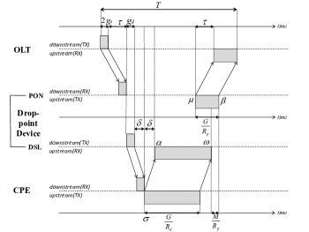
As illustrated in Figure 2, a CPE upstream transmission grant of size needs to be transmitted through both the DSL segment (CPE drop-point) and the PON segment (drop-point OLT). To determine when the transmission on the PON should begin, we must consider that the last bit of a packet must have arrived at the drop-point device from a CPE before the first bit of that same packet can be transmitted by the ONU to the OLT. We let denote the maximum packet size [in bit] and conservatively consider maximum size packets in the following analysis. Focusing on the last packet of the CPE upstream transmission, we note that the end of the last packet, i.e., the end of the CPE upstream transmission must be received by the drop-point before the ONU can forward this last packet over the PON to the OLT. We denote for the time instant when the CPE upstream transmission begins to arrive (and occupy buffer space) at the drop point, i.e.,
| (2) |
After complete receipt of the last packet at time instant
| (3) |
the ONU can immediately transmit this last packet to the OLT. We denote for the time instant when the last packet is completely transmitted by the ONU, i.e., when the CPE transmission stops to occupy buffer in the drop-point. Clearly,
| (4) |
The end of the last packet reaches the OLT after the PON propagation delay, resulting in the cycle duration .
For the last packet to be able to start ONU transmission at time instant , all preceding packets must have already transmitted by the ONU by time instant . More generally, the ONU finishes the transmission of the bits of CPE data by instant , if the ONU starts the PON upstream transmission (service) of the CPE data at time instant
| (5) |
We note that throughout this study we consider polling strategies that transmit CPE data at the full optical transmission bit rate on the PON upstream channel from ONU to OLT. Since the xDSL transmission bit rate is typically lower than the fiber transmission bit rate , the drop point needs to buffer a part of a CPE data transmission, which is received at rate at the drop point, before onward transmission at rate over the PON. Polling strategies that transmit on the PON upstream channel at a rate lower than can reduce drop point buffering at the expense of increased delay. The study of such strategies that only partially utilize the optical upstream transmission bit rate is left for future research.

III-D Drop-point Buffer Occupancy of a Single CPE
Based on the basic timing analysis in the preceding section, we characterize the buffer occupancy due to a single CPE in the drop-point. The buffer occupancy grows at rate [bit/s] from arrival instant of the CPE upstream transmission to the drop point until the starting instant of the ONU upstream transmission. From instant on the drop-point buffer drains at rate up to instant , when the CPE transmission has been completely received at the drop-point. From instant through the end of the ONU upstream transmission at , the buffer drains at rate . Since , the maximum buffer occupancy occurs at time instant when the ONU starts to serve (transmit) the CPE traffic. The drop-point has been receiving CPE data at rate since time instant , resulting in
| (6) |
Thus, the buffer occupancy of the drop point buffer associated with CPE is
| (7) |
and zero otherwise. For joint CPE buffering in the drop point (ONU), the superposition of the buffer occupancies
| (8) |
characterizes the occupancy level of the shared ONU buffer. The maximum of is the maximum ONU buffer occupancy.
III-D1 PON Segment Packet Delay
Considering maximum sized packets, the first packet of a given CPE upstream transmission is completely received by the drop point (ONU) at time instant . This first packet has to wait (queue) at the drop point until its transmission over the PON upstream wavelength channel commences at time instant . Thus, the queueing delay is , which can be expressed in terms of the maximum CPE buffer occupancy (6) as . The last packet of the CPE upstream transmission, which is completely received by the ONU at time instant (3), does not experience any queueing delay. Each packet experiences that transmission delay and propagation delay of the PON. Summing these delay components gives the total PON delay for a packet; and averaging over the packets in the CPE upstream transmission leads to the average packet delay on the PON segment.
III-E ONU:CPE Polling with Segregated CPE Transmissions on PON
In this section, we specify the Gated ONU:CPE polling protocol with segregated CPE transmissions on the PON upstream channels. That is, the data of each DSL CPE is transmitted upstream in its own sub-window of the overall ONU upstream transmission window. We consider CPEs attached to a given ONU. The ONU sends the CPE data transmissions successively according to a prescribed transmission order, as specified in Section III-E1, over the PON upstream wavelength channel. The CPEs time (schedule) their transmissions as specified in Section III-E2 to ensure that the CPE data arriving at rate to the ONU can be transmitted without interruptions at the full PON rate to the OLT.
III-E1 CPE Polling Order
The detailed analysis of the polling time with two CPEs in Appendix 1 indicates that the transmission order of CPE 1 followed by CPE 2 results in shorter cycle duration if
| (9) |
That is, transmitting the traffic from the CPE with the smaller grant size on the upstream PON channel before the CPE with the larger grant generally reduces the cycle duration, provided the round-trip propagation delays and between the ONU and the two CPEs are not too different. Typically, the CPEs are all in close vicinity of the ONU, thus the round-trip propagation delay differences are often negligible, even when scaled by the factor. For the remainder of this study we consider therefore the CPE transmission order with on the PON upstream transmission channel.
III-E2 CPE Transmission Timing
We derive the earliest time instant that the ONU can start upstream transmission such that all CPE data sets arrive in time to the drop-point for the ONU to continuously transmit at rate . Specifically, we prove the following theorem:
Theorem 1.
In order to meet the constraint of continuous (back-to-back) transmission of the data from CPEs in separate sub-transmission windows at the PON rate , the ONU can start transmission at the earliest at time instant
| (10) | |||||
whereby the ONU transmission starting instant , for an individual CPE is given by Eqn. (5).
Proof.
We consider initially two CPEs and . Considering each of these two CPEs individually, Eqn. (5) gives the respective time instants and when ONU service could at the earliest commence, when considering a given CPE in isolation.
There are two cases: If , then the earliest instant for the continuous ONU transmission to commence is . This is because the transmission of the data from CPE takes longer than CPE needs to get its data “ready” for ONU transmission.
If, on the other hand, , then the ONU transmission of CPE data must be delayed in order to avoid a gap between the end of the ONU transmission of the CPE data and the start of the ONU transmission of the CPE data. The earliest instant for the continuous ONU transmission to commence is , which gives the ONU just enough time to transmit the CPE data before the CPE data is “ready” for ONU transmission. In summary, the two cases for CPEs result in the earliest start time
| (11) |
for continuous ONU transmission at rate .
We proceed to the general case of CPEs by induction: Consider the continuous (back-to-back) ONU transmission of CPE and CPE data as one CPE transmission with earliest ONU transmission instant (when considered individually) . Next, we consider this back-to-back CPE and data as well as the CPE data. Analogous to (11), we obtain the earliest starting instant of the continuous ONU transmission of the data from CPEs , and 3:
| (12) |
Proceeding to the induction step with the continuous ONU transmission of the CPE data with earliest transmission instant as well as the CPE data results in the earliest transmission instant given by Eqn. (10) ∎
The sub-transmission window of CPE starts at , while CPE starts when the ONU transmission of CPE data is complete. Generally, the starting instants of the segregated CPE sub-transmission windows are
| (13) |
From these starting instants of the segregated CPE sub-transmission windows, we find the corresponding starting instants of the CPE transmissions by re-tracing the analysis in Section III-C. Briefly, for the continuous ONU transmission of the CPE data at rate is it sufficient for CPE to commence transmission before the end of the ONU transmission at instant , i.e.,
| (14) |
Starting the CPE transmissions at instead of the earliest possible (1) for an individual transmission reduces the drop-point buffer occupancy.
III-F ONU:CPE Polling with Multiplexed CPE Transmissions on PON
In this section, we specify the ONU:CPE polling protocol with statistical multiplexing of the packets from the individual CPEs in the ONU upstream transmission window. All DSL CPEs attached to the same drop-point statistically multiplex their transmissions into a joint ONU upstream transmission window (rather than in the separate sub-windows in Section III-E). The OLT effectively grants transmission windows to a given ONU to fit in all the traffic (in randomly statistically multiplexed order) of the DSL CPEs attached to the drop-point containing the ONU.
Theorem 2.
When the aggregate upstream transmission bit rate of the CPEs at an ONU is less than the PON upstream transmission bit rate, i.e., when , then the ONU can commence the continuous transmission of the multiplexed CPE data at the earliest at
| (15) | |||||
Proof.
The individual CPE upstream transmissions , can at the earliest be completely received by the drop point by time instants , whereby is given by Eqn. (1). The latest such instant of complete reception of the data from a CPE at the drop point is
| (16) |
If the aggregate transmission bit rate of the CPEs does not exceed the PON upstream transmission bit rate , the ONU can transmit all multiplexed CPE data upstream such that only one data packet, from at most each of the CPEs, remains to be transmitted after . Thus, the ONU can complete the upstream transmission by . Since the ONU has to transmit a total of bits of CPE data, the corresponding starting time instant of the ONU transmission must be before , resulting in the transmission start instant given by Eqn. (15). ∎
With the ONU transmission starting at instant , the ONU transmission is completed at instant . All CPE data has to arrive to the drop-point at least before the ONU transmission completion instant . CPE data is completely received by the drop point after the CPE transmission starting instant . Thus, CPE can start transmission at the latest at instant
| (17) |
IV Performance Evaluation
We conducted a wide set of simulations to answer three questions of practical interest:
-
1.
When is flow control required to provide a specific bound on ONU buffer occupancy without loss at the ONU?
-
2.
When does PAUSE frame flow control fail to provide a specific bound on ONU buffer occupancy without loss at the ONU?
-
3.
What is the range of bounds on ONU buffer occupancy without loss at the ONU that can be achieved with Gated flow control?
We used a PON/xDSL hybrid access network simulator that we developed using the CSIM discrete event simulation library. We considered the XGPON [45] protocol for the PON segment and the VDSL2 [43] protocol for the DSL segment as these two technologies are being actively deployed in real hybrid access networks. We set the XGPON upstream bit rate to Gbps and the guard time to 30 ns. The XGPON contained ONUs, each with attached VDSL lines (for a total of 256 CPEs). The upstream bit rate for each VDSL line was set to Mbps to achieve a realistic worst-case over-subscription rate of 8x. The OLT to ONU one-way propagation delays were continuously distributed between 2.5 s (i.e., 500 m) and 100 s (i.e., 20 km). The ONU to CPE propagation delays are considered negligible. We set the maximum cycle length to ms. The CPEs independently generated data packets according to a quad mode packet size distribution with 60 % 64 Byte packets, 4 % 300 Byte packets, 11 % 580 Byte packets, and 25 % 1518 Byte packets. Each simulation run for a given traffic load considered packets.
 |
 |
| a) No flow control (max. CPE buff.) | b) PAUSE frame flow control (max. CPE buff.) |
 |
 |
| c) No flow control (max. ONU buff.) | d) PAUSE frame flow control (max. ONU buff.) |
 |
 |
| e) No flow control (pkt. loss rate) | f) PAUSE frame flow control (pkt. loss rate) |
IV-A No Flow Control
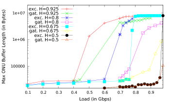
To answer question 1 we forgo the use of any flow control, utilize large CPE buffer capacities (1 MBytes), and monitor the maximum buffer occupancy. The DBA algorithm, source traffic burstiness, and presented traffic load are factors that will affect buffer occupancy at the ONU. Therefore, we vary these factors. We consider the (Online, Gated) and (Online, Excess) DBA algorithms that have been shown to provide good performance in conventional PONs [42], with a reporting approach akin to [46] for the newly generated traffic. Gated grant sizing assigns each ONU the full bandwidth request [15, 19]. The employed (Online, Excess) grant sizing approach assigns each ONU its request up to the maximum ONU grant size of Limited grant sizing [15, 19], i.e., an share of the total PON upstream transmission capacity in a cycle, plus a share of accumulated unused excess bandwidth (which was also limited to ) [47]; thus, the total maximum ONU grant is . We vary the burstiness of the traffic by using a self-similar traffic source in which we vary the Hurst parameter from 0.5 (equivalent to a Poisson traffic source) to 0.925 (equivalent to very bursty traffic).
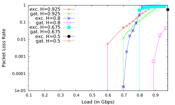
Fig. 4a), c), and e) contains plots of the maximum buffer occupancies and packet loss rate versus presented traffic load without the use of flow control. The traffic load is represented as a fraction of the full XGPON upstream transmission rate of 2.488Gbps. We define the maximum CPE buffer occupancy as the largest (maximum) of the maximum CPE buffer occupancies , see Fig. 3 and Eqn. (6), observed during a very long simulation considering over packet transmissions. The maximum ONU buffer occupancy is analogously defined as the largest aggregate of the CPE buffer occupancies, see Eqn. (8). Our primary observation from these plots is that the maximum buffer occupancy increases modestly until a certain “knee point” load value and then increases very sharply. The “knee point” load value depends on both the DBA algorithm and the burstiness of the source traffic. If the buffer occupancy below the knee point load value meets requirements, then flow control can be switched on just when the knee point load value is reached. As an example, when using the (Online, Excess) DBA algorithm, the maximum ONU buffer occupancy value before the knee point is 32 KB or less and the maximum CPE buffer occupancy is 10 KB or less. If 32 KB was the desired upper bound on the maximum aggregate ONU buffer occupancy, then flow control need only be activated once the presented load approached 0.94 for non-bursty traffic () or 0.4 for highly bursty traffic (). Not surprisingly, bursty traffic will require flow control under wider load conditions than non-bursty traffic.
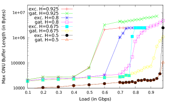
IV-B ONU Polling PAUSE Frame Flow Control
To answer question 2 we use PAUSE frame flow control with a threshold of 35 % buffer capacity to trigger the transmission of PAUSE frames with a duration of 2 ms. A set of experiments, that we leave out due to space constraints, were conducted to explore that two-dimensional parameter space of buffer threshold and PAUSE duration. Those experiments indicated that (35%, 2 ms) provided the best performance.
Figure 4b), d), and f) contains plots of the maximum buffer occupancies and packet loss rates versus presented traffic load with PAUSE frame flow control. We observe that the maximum buffer occupancy trends when using PAUSE frame flow control are similar to when no flow control is used. A notable exception is that for the (Online, Excess) DBA algorithm, the maximum CPE buffer occupancy stays below approximately 300 KB when PAUSE frame flow control is used, compared to 1 MB (i.e., the full capacity) when no flow control is used. For the (Online, Gated) DBA algorithm, the maximum CPE buffer occupancy reaches the 1 MB buffer capacity for highly bursty traffic ( and 0.925), regardless of whether PAUSE frame flow control is used. The unlimited grant sizes of the (Online, Gated) DBA algorithm appear to undermine the efforts of flow control.
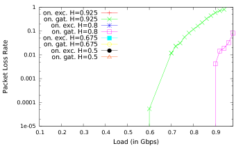
From the packet loss rate plots in Figure 4e) and f) we observe that when using the (Online, Excess) DBA algorithm, PAUSE frame flow control can eliminate packet losses. On the other hand, for the (Online, Gated) DBA algorithm with unlimited grant sizes, PAUSE frame flow control is unable to lower the packet loss rate for the bursty and 0.925 traffic.
 |
 |
| a) Max. CPE buffer occupancy | b) Max. ONU buffer occupancy |
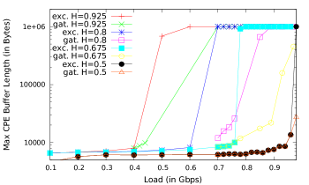
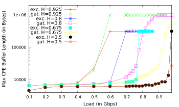
IV-C GATED ONU:CPE Polling Flow Control
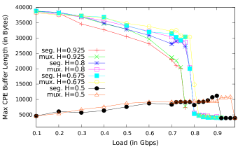
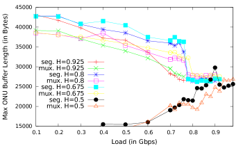
To answer question 3 we present results for the two Gated ONU:CPE polling flow control protocols introduced in Section III, namely segregated (ONU:CPE:seg) and multiplexing (ONU:CPE:mux) polling flow control. We continue to consider the (Online, Excess) sizing for the ONU grants. A given ONU grant is distributed to the CPEs according to the equitable iterative excess distribution method [48, 49], which fairly divides the ONU grant among the CPEs, allowing CPEs with high traffic loads to utilize the unused fair shares of the low traffic loads. Figure 5 contain plots of the maximum buffer occupancies and average packet delays as a function of load.
IV-C1 Maximum CPE and ONU Buffer Occupancies
We observe from Figure 5 that for low loads of bursty traffic with Hurst parameters , the maximum CPE and ONU buffer occupancies are approximately twice the maximum ONU grant size of a Limited DBA grant sizing at low traffic loads, i.e., approximately . At low bursty traffic loads it is likely that only very few CPEs (that are attached to only a few ONUs) generate a traffic burst at a given time, while the other CPEs have no traffic. This permits the ONUs with attached CPEs with a traffic burst through the considered Online Excess DBA mechanism [48, 49, 47] to utilize the excess bandwidth allocation from the ONUs without traffic bursts. The considered Online Excess DBA limits the excess allocation from other ONUs to a given ONU to once the maximum Limited DBA grant size. Thus, if a single CPE at an ONU generates a traffic burst, the CPE is allocated a grant of twice the maximum Limited DBA grant size, resulting in correspondingly large maximum CPE and ONU buffer occupancies. (The ONU buffer occupancies slightly above 40 kB are due to small residual backlog from preceding cycles due to the different DSL and PON framing mechanisms, see Section III-B.)
Interestingly, we observe from Figure 5 that the maximum CPE and ONU buffer occupancies in the bursty () traffic scenarios decrease with increasing traffic load. As the traffic load increases, more and more CPEs have backlogged (queued) traffic bursts. When all ONUs have some CPEs with backlogged traffic, there is no more excess allocation from ONUs with little or no traffic backlog to ONUs with large traffic backlog. Thus, the Online Excess DBA mechanism turns into the Online Limited DBA mechanism and allocates to each ONU the maximum Limited DBA ONU grant size. Thus, as the traffic load increases, the traffic amount transmitted upstream on the PON bandwidth is more equally distributed among the ONUs as more and more ONUs have CPEs with backlogged traffic bursts. In turn, the grant allocation to a given ONU is more equally divided among its attached CPEs as the traffic load increases and more and more CPEs at an ONU have backlogged traffic bursts.
For the Poisson traffic scenario (), we observe from Fig. 5 that the CPE and ONU buffer occupancies continuously increase with increasing traffic load (except for a drop in CPE buffer occupancy at very high loads). In contrast to bursty traffic sources that generate bursts of several packets at a time, Poisson traffic sources generate individual data packets. These individually generated packets are uniformly distributed (spread) among the CPEs, and correspondingly the ONUs. Thus, there is essentially no excess allocation among ONUs at low load levels and the maximum CPE and ONU buffer occupancies grow gradually with increasing traffic load. (For high load levels there is some excess allocation, which decreases at very high loads as all CPEs and ONUs have backlogged traffic, resulting in the CPE buffer occupancy drop at very high loads.)
In additional simulations, we observed that for the Online, Gated PON DBA, which grants the ONUs the full bandwidth requests [19], the maximum CPE and ONU buffer occupancies depend mainly on the burstiness of the traffic: around 10 kBytes for Poisson traffic and on the order of 10 MBytes for bursty traffic with , for the considered network scenario. In contrast, for the Online, Limited PON DBA, which strictly limits the grant allocation to an ONU to a prescribed limit (and does not permit re-allocations among ONUs which are possibly in the Online, Excess PON DBA) [19], we have observed that the maximum CPE and ONU buffer occupancies are generally bounded by the maximum ONU grant size [38]. Thus, our extensive simulations have validated that Gated ONU:CPE polling flow control effectively limits the maximum CPE and ONU buffer occupancies through the employed grant sizing mechanisms.
 |
 |
| a) DSL delay | b) PON delay |
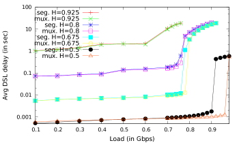
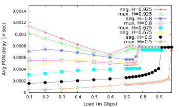
IV-C2 DSL and PON Delay
We observe from Figure 6 that the DSL delay component from the instant of packet generation to the complete packet reception at the drop point (ONU) increases first slowly for low loads. Then, for moderately high loads above 0.6, we begin to observe rapidly increasing DSL delays, first for the highly bursty traffic and then at higher loads above 0.75 for the and traffic scenarios. The DSL delays for these scenarios shoot up to values above 18 s (i.e., outside the plotted range) as the traffic bursts overwhelm the system resources. In contrast, for Poisson traffic, we observe steadily increasing delays that remain below 1 s even for very high traffic loads. We also observe that the “mux” approach, which multiplexes upstream transmissions from different CPEs on the upstream PON wavelength channel achieves lower delays than the “seg” approach with segregated CPE upstream transmissions on the PON. The DSL delay reduction achieved with the multiplexing approach is particularly pronounced for high Poisson traffic loads, where the multiplexing approaches reduces the DSL delay by over 0.5 s compared to the corresponding delay with the segregated approach.
The PON segment delay of a packet from the instant of packet reception at the drop point (ONU) to the instant of packet reception at the ONU depends on the CPE buffer occupancies, as analyzed in Section III-D1. Essentially, for the segregated CPE transmission approach, the average PON packet delay corresponds directly (is proportional) to the average of the maximum CPE buffer occupancies across the individual polling cycles.
We observe from Fig. 6 initially (in the low load region) decreasing PON delay with increasing load for the highly bursty traffic, The other traffic scenarios give initially slowly increasing PON delays that rapidly increase for high loads in the 0.75–0.95 load range and then level out. For the very bursty traffic, the individual (average) maximum CPE buffer occupancies of payload data packets (i.e., ignoring the drop point buffer occupancy of CPEs sending only Report control packets) are initially very large due to the traffic bursts at individual CPEs and associated ONUs, which receive excess allocations from the other ONUs (similar to the dynamics for low loads in Fig. 5). These excess allocations diminish as CPEs at more and more ONUs get backlogged, resulting in a decrease of the average maximum CPE buffer occupancies, and correspondingly a decrease of the average PON packet delay.
For the other traffic scenarios with and lower, the burstiness is less pronounced, avoiding a decrease of the average maximum CPE buffer occupancy for increasing loads in the low load region, whereas the largest (across a long simulation run) maximum CPE buffer occupancy does exhibit a significant decrease, see Fig. 5. For very high loads, the average PON packet delay, which is proportional to the average maximum CPE buffer occupancy, levels out around 0.8 ms. This leveling out is analogous to the leveling out of the largest maximum CPE buffer occupancy in Fig. 5). We note that the average PON packet delay of roughly 0.8 ms is substantially longer than the maximum PON packet delay obtained with the delay analysis in Section III-D1 for the maximum CPE buffer occupancy of roughly 5 kB for very high loads in Fig. 5. The analysis in Section III-D1 neglects the small residual drop point buffering. However, the relatively few packets that make up the residual buffering have to wait approximately the full cycle length ms for upstream transmission in the next cycle; thus, substantially increasing the mean PON packet delay. Nevertheless, due to the flow control back-pressuring the data into the CPEs until an ONU grant can accommodate the CPE data transmissions, the PON segment delays are minuscule compared to the DSL segment delays.
We observe from Fig. 6 that multiplexing CPE transmissions gives generally lower PON delays than segregating CPE transmissions. The delay analysis in Section III-D1 applies directly to segregated CPE transmissions in that the CPE buffer in the drop point is filled at the rate of a single DSL line. The CPE buffer is filled until the full optical transmission rate can be sustained for the transmission of all CPE data sets over the PON. When multiplexing CPE transmissions, multiple DSL lines supply data to the drop point. Thus, the PON transmission can commence earlier, resulting in shorter queueing delays for the first packets that arrived from the CPEs to the drop point.
V Conclusion
We have examined the buffering in the drop-point device connecting the relatively low-transmission rate xDSL segment to the relatively high-transmission bit rate PON segment in a hybrid PON/xDSL access network. We found that the drop-point device experiences very high buffer occupancies on the order of Mega Bytes or larger when no flow control or when flow control with the standard Ethernet PAUSE frame are employed. In an effort to reduce the buffer occupancies in the drop points and thus to reduce the energy consumption of the drop point devices, which are typically reverse powered from subscribers, we introduced Gated ONU:CPE polling flow control protocols. We specified the timing (scheduling) of these Gated ONU:CPE polling flow control protocols for two types of upstream transmission: segregated CPE sub-windows or multiplexed CPE transmissions within an ONU upstream transmission window. Through extensive simulations for a wide range of levels of traffic burstiness, we verified that the Gated ONU:CPE polling protocols effectively limit the drop-point buffering in individual CPE buffers or an aggregated ONU buffer. The maximum CPE and ONU buffer occupancies correspond approximately to the grant size limits of the polling-based medium access executed at the OLT. Through adjusting the ONU and CPE grant sizes in the proposed Gated ONU:CPE polling flow control protocols, the OLT can effectively control the buffering in the drop-point devices.
One important direction for future research on hybrid access networks is to extend the hybrid access network evaluation to the local wired and wireless networks that interconnect with the access network at the CPE. Excessive buffering in the CPEs could be mitigated by further back-pressuring the data transmissions to the gateways or host whose applications generate large traffic flows. Another important direction for future research is to examine control mechanisms through software defined networking in hybrid access networks [50].
Acknowledgment
This material is based upon work supported by the National Science Foundation under Grant No. CNS-1059430 and by a gift from Huawei Technologies.
 |
 |
 |
| (a) | (b) | (c) |
Appendix: Analysis of CPE Transmission Ordering for Two CPEs
We assume for the following analysis without loss of generality that CPE 1 has a smaller propagation delay to the drop-point device than CPE 2 (i.e., ). We analyze the minimum delay for complete reception of both upstream transmissions at the OLT. There are three main cases for evaluating , as illustrated in Fig. 7:
Case small , see Fig. 7(a)
There is a gap between the CPE partitions on the PON since is too small to mask the time until is ready for PON upstream transmission. (In this small case, the transmission of CPE 1 could be delayed so as to avoid the occurrence of a gap, and reduce the time that the ONU buffer holds the CPE 1 data.)
Case medium , see Fig. 7(b)
The partitions of CPE 1 and CPE 2 are transmitted back-to-back on the PON.
Case large , see Fig. 7(c)
is so large that the PON upstream transmission of is completed before is ready for PON upstream transmission.
We proceed to analyze the transmission order of the CPE transmission windows on the PON and identify the minimum times for complete reception of both CPE data transmissions at the OLT. We denote with 12 the transmission order CPE 1 followed by CPE 2, and denote 21 for the reverse transmission order. To reduce clutter in this scheduling analysis, we re-define the time periods and from Section III-C with reference to the end of the downstream gate transmission by the ONU.
In order to identify the threshold that distinguishes the small and medium cases we initially consider the transmissions of CPE 1 and CPE 2 as completely independent, i.e., we initially only consider one of these CPE transmissions at a time. From Fig. 7(a), we note that the time period from the ending instant of the gate message transmissions by the ONU to the time instant that the ONU transmission of CPE 1 data is completed as
| (18) |
Similarly, we express the time period until the time instant of the beginning of the CPE 2 data transmission on the PON as
| (19) |
The transmission of CPE 1 data by the ONU is completed before the ONU transmission of CPE 2 data can commence if , i.e., if
| (20) |
Thus, for , the transmission of CPE 1 data before CPE 2 data does not delay the commencement of CPE 2 data transmission. Hence, the transmission order 12 achieves the minimum cycle (completion) time
| (21) |
Next, we identify the threshold that distinguishes the medium and large cases. We note from Fig. 7(c) that the ONU transmission of CPE 2 data is completed by
| (22) |
The ONU transmission of CPE 1 data can commence at the earliest at time
| (23) |
For , or equivalently, for
| (24) |
the ONU transmission of CPE 1 data is completed before the ONU transmission of CPE 2 data can commence That is, the CPE 2 data transmission does not delay the CPE 1 data transmission. Thus, the 21 transmission order gives the minimum completion time
| (25) |
Note also that .
We now turn to the medium range illustrated in Fig. 7(b). We note from the illustration in Fig. 7(b) that the completion time for the 12 transmission order is
| (26) |
We similarly obtain the completion time for the 21 transmission order and note that
| (27) | |||||
| (28) | |||||
| (29) |
Thus, the transmission order 12 gives the minimum if .
In summary, the minimum time period from the instant of commencing the transmission of the gate messages from the OLT to the complete reception of both CPE data transmissions at the OLT is obtained by the transmission order CPE 1 data followed by CPE 2 data on the PON for . For , the reverse transmission order of CPE 2 data followed by CPE 1 data on the PON minimizes .
References
- [1] T. Koonen, “Fiber to the home/fiber to the premises: What, where, and when?” Proceedings of the IEEE, vol. 94, no. 5, pp. 911–934, May 2006.
- [2] F. Mazzenga, M. Petracca, F. Vatalaro, R. Giuliano, and G. Ciccarella, “Coexistence of FTTC and FTTDp network architectures in different VDSL2 scenarios,” Trans. on Emerging Telecommun. Techn., in print, 2015.
- [3] T. Starr, J. Cioffi, and P. Silverman, Understanding digital subscriber line technology. Prentice Hall, 1999.
- [4] Y. Luo, “Activities, drivers and benefits of extending PON over other media,” in Proc. OSA NFOEC, Mar. 2013, pp. 1–3.
- [5] S. Ahamed, P. Bohn, and N. Gottfried, “A tutorial on two-wire digital transmission in the loop plant,” IEEE Transactions on Communications, vol. 29, no. 11, pp. 1554–1564, Nov. 1981.
- [6] G. Ginis and J. Cioffi, “Vectored transmission for digital subscriber line systems,” IEEE J. Selected Areas in Communications, vol. 20, no. 5, pp. 1085–1104, Jun 2002.
- [7] B. Lee, J. Cioffi, S. Jagannathan, and M. Mohseni, “Gigabit DSL,” IEEE Transactions on Communications, vol. 55, no. 9, pp. 1689–1692, Sept. 2007.
- [8] “ITU-T G.9701, Fast access to subscriber terminals (G.fast) - Physical layer specification,” http://www.itu.int/rec/T-REC-G.9701/en.
- [9] M. Timmers, M. Guenach, C. Nuzman, and J. Maes, “G.fast: evolving the copper access network,” IEEE Communications Magazine, vol. 51, no. 8, pp. 74–79, Aug. 2013.
- [10] J. Stern, J. Ballance, D. Faulkner, S. Hornung, D. Payne, and K. Oakley, “Passive optical local networks for telephony applications and beyond,” IET Electronics Letters, vol. 23, no. 24, pp. 1255–1256, Nov. 1987.
- [11] N. Frigo, P. Iannone, P. Magill, T. Darcie, M. Downs, B. Desai, U. Koren, T. Koch, C. Dragone, H. Presby, and G. Bodeep, “A wavelength-division multiplexed passive optical network with cost-shared components,” IEEE Photonics Technology Letters, vol. 6, no. 11, pp. 1365–1367, Nov. 1994.
- [12] G. Kramer and G. Pesavento, “Ethernet passive optical network (epon): building a next-generation optical access network,” IEEE Communications Magazine, vol. 40, no. 2, pp. 66–73, Feb. 2002.
- [13] M. Dias, E. Wong, D. Pham Van, and L. Valcarenghi, “Offline energy-efficient dynamic wavelength and bandwidth allocation algorithm for TWDM-PONs,” in Proc. IEEE ICC, 2015, pp. 5018–5023.
- [14] I. Gravalos, K. Yiannopoulos, G. Papadimitriou, and E. Varvarigos, “The max–min fair approach on dynamic bandwidth allocation for XG-PONs,” Trans. Emerging Telecommun. Techn., vol. 26, no. 10, pp. 1212–1224, 2015.
- [15] G. Kramer, B. Mukherjee, and G. Pesavento, “IPACT: A dynamic protocol for an Ethernet PON (EPON),” IEEE Communications Magazine, vol. 40, no. 2, pp. 74–80, Feb. 2002.
- [16] P. Sarigiannidis, G. Papadimitriou, P. Nicopolitidis, E. Varvarigos, M. Louta, and V. Kakali, “IFAISTOS: A fair and flexible resource allocation policy for next-generation passive optical networks,” in Proc. IEEE (ICUMT), 2014, pp. 7–14.
- [17] B. Skubic, J. Chen, J. Ahmed, L. Wosinska, and B. Mukherjee, “A comparison of dynamic bandwidth allocation for epon, gpon, and next-generation tdm pon,” IEEE Communications Magazine, vol. 47, no. 3, pp. S40–S48, Mar. 2009.
- [18] Ö. C. Turna, M. A. Aydın, A. H. Zaim, and T. Atmaca, “A new dynamic bandwidth allocation algorithm based on online–offline mode for EPON,” Opt. Switching and Netw., vol. 15, pp. 29–43, 2015.
- [19] J. Zheng and H. Mouftah, “A survey of dynamic bandwidth allocation algorithms for Ethernet Passive Optical Networks,” Optical Switching and Networking, vol. 6, no. 3, pp. 151–162, July 2009.
- [20] M. Ahmed, I. Ahmad, and D. Habibi, “Service class resource management for green wireless-optical broadband access networks (WOBAN),” IEEE/OSA Journal of Lightwave Techn., vol. 33, no. 1, pp. 7–18, 2015.
- [21] L. Fang, L. Zhou, X. Liu, X. Zhang, M. Sui, F. Effenberger, and J. Zhou, “Demonstration of end-to-end cloud-DSL with a PON-based fronthaul supporting 5.76-Gb/s throughput with 48 eCDMA-encoded 1024-QAM discrete multi-tone signals,” OSA Optics Express, vol. 23, no. 10, pp. 13 499–13 504, 2015.
- [22] G. Kramer, M. D. Andrade, R. Roy, and P. Chowdhury, “Evolution of optical access networks: Architectures and capacity upgrades,” Proceedings of the IEEE, vol. 100, no. 5, pp. 1188–1196, May 2012.
- [23] R. Gaudino, R. Giuliano, F. Mazzenga, F. Vatalaro, and L. Valcarenghi, “Unbundling in optical access networks: Focus on hybrid fiber-VDSL and TWDM-PON,” in Proc. Fotonica AEIT Italian Conf. on Photonics Techn., 2014, pp. 1–4.
- [24] S. Sarkar, S. Dixit, and B. Mukherjee, “Hybrid wireless-optical broadband-access network (WOBAN): A review of relevant challenges,” IEEE/OSA Journal of Lightwave Technology, vol. 25, no. 11, pp. 3329–3340, Nov. 2007.
- [25] A. Ahmed and A. Shami, “RPR–EPON–WiMAX hybrid network: A solution for access and metro networks,” IEEE/OSA Journal of Optical Commun. and Netw., vol. 4, no. 3, pp. 173–188, 2012.
- [26] N. Ghazisaidi, M. Maier, and C. Assi, “Fiber-wireless (FiWi) access networks: A survey,” IEEE Communications Magazine, vol. 47, no. 2, pp. 160–167, Feb. 2009.
- [27] I. Cooper and M. Bramhall, “ATM passive optical networks and integrated VDSL,” IEEE Communications Magazine, vol. 38, no. 3, pp. 174–179, Mar. 2000.
- [28] I. Cooper, V. Barker, M. Andrews, M. Bramhall, and P. Ball, “Video over BPON with integrated VDSL,” Fujitsu Scientific and Technical Journal, vol. 37, no. 1, pp. 87–96, June 2001.
- [29] R. Roka, “The analysis of the effective utilization of PON and VDSL technologies in the access network,” in Proc. IEEE EUROCON, vol. 1, Sept. 2003, pp. 216–219.
- [30] C. Assi, Y. Ye, and S. Dixit, “Support of QoS in IP-based Ethernet-PON,” in Proc. IEEE Globecom, vol. 7, Dec. 2003, pp. 3737–3741.
- [31] J. Lepley, M. Thakur, I. Tsalamanis, C. Bock, C. Arellano, J. Prat, and S. Walker, “VDSL transmission over a fiber extended-access network,” OSA Journal of Optical Networking, vol. 4, no. 8, pp. 517–523, Aug. 2005.
- [32] G. Wu, D. Liu, S. Zhang, C. Zhang, and Y. Chang, “Novel access technology based on hybrid Ethernet passive optical network and ethernet passive electronic network,” Frontiers of Optoelectronics in China, vol. 2, no. 3, pp. 328–333, Sept. 2009.
- [33] J. Wei, “The VoD services carried by hybrid PON+EoC networking,” in Proc. IEEE Int. Conf. on Broadband Network Multimedia Tech. (IC-BNMT), Oct. 2009, pp. 467–471.
- [34] P. Bhaumik, S. Thota, B. Mukherjee, K. Zhangli, J. Chen, H. Elbakoury, and L. Fang, “EPON protocol over coax (EPoC): overview and design issues from a MAC layer perspective?” IEEE Communications Magazine, vol. 51, no. 10, pp. 144–153, Oct. 2013.
- [35] P. Bhaumik, S. Thota, K. Zhangli, J. Chen, H. ElBakoury, L. Fang, and B. Mukherjee, “EPON Protocol over Coax (EPoC): Round-trip time aware dynamic bandwidth allocation,” in Proc. IEEE Int. Conf. on Optical Network Design and Modeling (ONDM), Apr. 2013, pp. 287–292.
- [36] ——, “On downstream transmissions in EPON protocol over coax (EPoC): An analysis of coax framing approaches and other relevant considerations,” Photonic Network Communications, vol. 28, no. 2, pp. 178–189, Oct. 2014.
- [37] M. McGarry, E. Gurrola, and Y. Luo, “On the reduction of ONU upstream buffering for PON/xDSL hybrid access networks,” in Proc. Globecom, Dec. 2013, pp. 2667–2673.
- [38] A. Mercian, E. Gurrola, M. McGarry, and M. Reisslein, “Improved polling strategies for efficient flow control for buffer reduction in PON/xDSL hybrid access networks,” in Proc. IEEE Asilomar Conf. on Signals, Systems, and Computers, Nov. 2015.
- [39] M. Hossen and M. Hanawa, “Multi-OLT and multi-wavelength PON-based open access network for improving the throughput and quality of services,” Opt. Switching and Netw., vol. 15, pp. 148–159, 2015.
- [40] B. Kantarci and H. T. Mouftah, “Bandwidth distribution solutions for performance enhancement in long-reach passive optical networks,” IEEE Commun. Surveys & Tutorials, vol. 14, no. 3, pp. 714–733, 2012.
- [41] N. Merayo, T. Jiménez, P. Fernández, R. J. Durán, R. M. Lorenzo, I. de Miguel, and E. J. Abril, “A bandwidth assignment polling algorithm to enhance the efficiency in QoS long-reach EPONs,” European Trans. on Telecommunications, vol. 22, no. 1, pp. 35–44, 2011.
- [42] M. McGarry and M. Reisslein, “Investigation of the DBA algorithm design space for EPONs,” IEEE/OSA Journal of Lightwave Technology, vol. 30, no. 14, pp. 2271–2280, July 2012.
- [43] “ITU-T G.993.2, Very high speed digital subscriber line transceivers 2 (VDSL2),” http://www.itu.int/rec/T-REC-G.993.2/en.
- [44] “ITU-T G.992.3, Asymmetric digital subscriber line transceivers 2 (ADSL2),” http://www.itu.int/rec/T-REC-G.992.3/en.
- [45] “ITU-T G.987.3, 10-Gigabit-capable passive optical networks (XG-PON): Transmission convergence (TC) specifications,” http://www.itu.int/rec/T-REC-G.987.3/en.
- [46] B. Skubic, J. Chen, J. Ahmed, B. Chen, L. Wosinska, and B. Mukherjee, “Dynamic bandwidth allocation for long-reach PON: overcoming performance degradation,” IEEE Communications Magazine, vol. 48, no. 11, pp. 100–108, 2010.
- [47] A. Mercian, M. McGarry, and M. Reisslein, “Offline and online multi-thread polling in long-reach PONs: A critical evaluation,” IEEE/OSA J. Lightwave Techn., vol. 31, no. 12, pp. 2018–2028, 2013.
- [48] C. Assi, Y. Ye, S. Dixit, and M. Ali, “Dynamic bandwidth allocation for quality-of-service over Ethernet PONs,” IEEE Journal on Selected Areas in Communications, vol. 21, no. 9, pp. 1467–1477, Nov. 2003.
- [49] X. Bai, A. Shami, and C. Assi, “On the fairness of dynamic bandwidth allocation schemes in Ethernet passive optical networks,” Computer Communications, vol. 29, no. 11, pp. 2123–2135, 2006.
- [50] K. Kerpez, J. Cioffi, G. Ginis, M. Goldburg, S. Galli, and P. Silverman, “Software-defined access networks,” IEEE Communications Magazine, vol. 52, no. 9, pp. 152–159, 2014.