Avoiding Tokamak disruptions by applying static magnetic fields that
align locked modes with stabilizing wave-driven currents
Abstract
Non-rotating (‘locked’) magnetic islands often lead to complete losses of confinement in tokamak plasmas, called major disruptions. Here locked islands were suppressed for the first time, by a combination of applied three-dimensional magnetic fields and injected millimetre waves. The applied fields were used to control the phase of locking and so align the island O-point with the region where the injected waves generated non-inductive currents. This resulted in stabilization of the locked island, disruption avoidance, recovery of high confinement and high pressure, in accordance with the expected dependencies upon wave power and relative phase between O-point and driven current.
pacs:
The international ITER c1 tokamak has the objective of demonstrating the scientific feasibility of magnetic confinement fusion as a source of energy. A concern towards the achievement of this goal is represented by major disruptions c1 : complete losses of confinement often initiated c3 by a non-rotating (‘locked’) magnetic island created by magnetic reconnection c4 . During disruptions, energy and particles accumulated in the plasma volume over several confinement times (seconds in ITER, a fraction of a second in present experiments) are lost in a few milliseconds and released on the plasma-facing materials c5 . In addition, multi-MA level currents flowing in the tokamak plasma for its sustainment and confinement are lost, also in milliseconds, thus terminating the plasma discharge and causing electromagnetic stresses that, if unmitigated, could lead to excessive device wear. Here it is shown for the first time that magnetic perturbations can be used to avoid disruptions by “guiding” the magnetic island to lock in a position where it is accessible to millimetre wave beams that fully stabilize it. Stabilization is due to locally wave-driven currents (Electron Cyclotron Current Drive, or ECCD).
Magnetic control of island rotation DITE and stabilization of rotating islands by ECCD c9 were separately demonstrated in the past. Currents were either continuously driven c9 or, more efficiently, they were modulated in synch with the spontaneous island rotation c10 . Electron Cyclotron Heating (ECH) was also used for stabilization Classen , but is predicted to scale unfavorably to large hot plasmas c18 . Two experiments combined magnetic perturbations -to produce the island- with ECH that stabilized it: in the first one the mode was born locked to a given phase and was stabilized by continuous ECH Morris2 ; the second one controlled island rotation and stabilized the mode by modulated ECH TEXTOR .
However, if the rotating island (typically a spontaneous, pressure-driven ’Neoclassical Tearing Mode’) is not preempted or stabilized (due for example to late intervention, misalignment, or insufficient power being used for this purpose), or if the island does not ever rotate at all, it becomes necessary to suppress the locked mode. This capability was numerically modeled Yu , experimentally tested c20 , and is fully demonstrated here for the first time. Without this capability, the locked mode would grow and promptly lead to a disruption. After that, only one last line of defense would remain, namely to mitigate the disruption, for instance by massive gas injection c1 ; c11 .
Static, rather than rotating fields TEXTOR ; c20 , are used here, permitting to align the plasma such that ECCD can be continuously deposited into the location of the locked mode where it has a stabilizing effect on it. By contrast, continuous ECCD on rotating islands is always on, but only stabilizing half of the time c9 ; c20 , and modulated ECH/ECCD on rotating islands is on and stabilizing half of the time, if properly phased c10 ; TEXTOR .
Locked mode control will be needed in ITER, where (1) islands will be locked for most of their lifetime and (2) alignment will be challenging. This is because islands of poloidal/toroidal mode number =1 are expected to lock as soon as they exceed a width of 5 cm, i.e. seconds after forming c12 ; c13 and well before reaching an ultimate width of 35-40 cm c14 . Hence, it will be challenging to precisely aim the ECCD for preemption or in the brief period of time when the island is still rotating, but very small. This will require few cm of precision at several meters from the wave launcher, resulting in 0.2 degrees of angular precision c15 , whereas locked modes are larger, easier targets. In addition, rapid locking sets a requirement for rapid mirror steering, if one wants to align the ECCD and stabilize the mode when still rotating.
The locked island O-point (i.e. the local magnetic axis of the island) can lock in a position not necessarily accessible to the mm-waves. In the absence of position control, one can apply ECH only (no current drive) to delay or avoid disruptions in small c16 and mid-size devices c17 . This approach, as mentioned, is predicted to scale unfavourably to larger, hotter fusion plasmas such as ITER, where the stabilization is expected to be completely governed by current drive c18 . Yet, in order for current drive to be used, it is necessary to gain control of the locking position of the magnetic island, as currents driven at the wrong location, such as the island X-point (the tip of the island), can actually be destabilizing c19 .
The island is caused by a helical “hole” in a pressure-driven (“bootstrap”) current c18 and can be modelled with multiple helical filaments offset in the toroidal angle and carrying different currents, according to a sinusoidal distribution Shiraki . A magnetic dipole is associated with this helical current pattern. When not controlled, the magnetic dipole of an initially rotating =1 mode, slowed down by the interaction with the currents induced in the resistive wall of the tokamak, tends to align with the =1 “error” in the otherwise axisymmetric tokamak field. Error fields as small as one part in - of the main toroidal field are sufficient to cause a pre-existing rotating island to lock, or to directly cause a non-rotating (locked) island to form.
In both cases, the azimuthal angle (toroidal phase) of the locked island is determined by the error field. In previous work, slowly rotating perturbations were superimposed to it, and the resultant acted as “magnetic tweezers” that slowly rotated the locked mode c20 . In the present work, static =1 magnetic perturbations are applied as soon as a rotating magnetic island is magnetically detected to decelerate, before it comes to a complete stop. Their amplitude and toroidal phase are chosen in such a way that, when the island locks to the total =1 field, its O-point is toroidally aligned with the ECCD deposition region. The optimal perturbation yielding good alignment can either be calculated in advance (if the error field is known), be experimentally optimized (as in the experiments presented here), or it can be chosen to be strong enough as to dominate over the error field in determining the toroidal phase of the island, . In any case, it should be mentioned that, due to the low toroidal number of the mode, =1, the optimal “target” for the mm-waves is toroidally elongated. Therefore, once a means of controlling is available, the necessary precision in is relatively low, of the order of . With this phase control in hand, the current drive mechanism, which can be stabilizing or destabilizing, can be effectively used to control the locked mode amplitude as desired, i.e. to fully stabilize the mode and avoid the disruption.
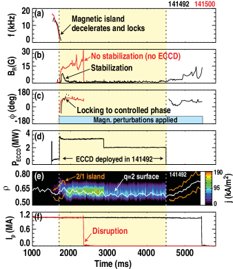
Fig.1 shows two plasma discharges realized at the DIII-D tokamak c22 and characterized by locked modes. In the discharge depicted in black, the simultaneous use of magnetic perturbations for phase-control and of mm-waves for amplitude-control resulted in rapid stabilization of the locked mode (Fig.1b). The stabilization is considered complete because the radial field signal measured with inductive sensors c23 decreases to the 1 G level, which is consistent with noise and with other =1 activity. Importantly, the disruption is avoided for as long as both controls are deployed. If magnetic perturbations alone are used (discharge depicted in red) or mm-wave current drive is turned off (black discharge at time =4500 ms), the mode grows and disrupts the discharge, as exemplified by the dramatic drop in plasma current (Fig.1f).
It is also experimentally confirmed that:
-
1.
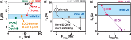
To be stabilizing, the driven current needs to be deposited in the O-point of the locked island, whereas deposition in the X-point is destabilizing. The effect of deposition in an intermediate location is, indeed, intermediate, i.e. neither strongly stabilizing nor strongly destabilizing (Fig.2a). Note that the three cases plotted differ by the orientation of the applied non-axisymmetric field, and thus by the amplitude of the total non-axisymmetric field. However, this was recently found to have negligible effect on the locked island c24 . Also note that the island moves slightly after locking. Its initial phase is magnetically controlled by the applied fields, which are subsequently kept constant. The change of phase is ascribed to changes in the error field and in the viscous, neutral beam and electromagnetic torques acting on the island, reaching balance at a new phase. In turn, such torques change as a consequence of the very fact that the island size and island current evolve.
-
2.
Higher mm-wave power, all the rest remaining the same, has a more stabilizing effect (Fig.2b). This is due to more intense stabilizing currents being driven.
-
3.
The key requisite for stabilization is that the applied wave-driven current compensates or overcompensates for the missing pressure-driven bootstrap current responsible for the formation of the island. To this end, it is more efficient to use the available wave power to drive maximum current. This is obtained for injection at an appropriate oblique angle relative to the magnetic field c25 . If, instead, injection is perpendicular or nearly perpendicular to the field, the main effect is some heating but little or no current, which typically is insufficient for complete stabilization (Fig.2c).
In addition to disruption avoidance, locked mode control provides benefits for confinement, compared with non-stabilized discharges. At the same time, an increase in confinement represents an additional, indirect evidence that the island was stabilized. The reason is that a large island alters the magnetic topology in a way that creates a local short circuit for heat and particles, degrading confinement c26 . Therefore, the suppression of the large locked island restores good particle and energy confinement, density , temperature and their product (the kinetic pressure), as well as high normalized pressure , defined as the ratio between the kinetic pressure of the plasma and the magnetic pressure used to confine it, normalized to , where is the plasma current in mega-amperes, the minor radius in meters and the magnetic field in Tesla.
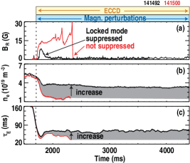
The suppression of the locked island allows an edge transport barrier to re-form, thus re-establishing the so called high confinement mode, or H-mode c27 (Fig.4c). As a result, higher electron density and energy confinement time are achieved when the locked mode is suppressed (Fig.3, black), compared with when the mode is not suppressed (red). Two factors, though, limit the increase of . One is that the mm-wave power is intended for mode suppression, not heating. It is deposited near the plasma edge and quickly lost. The other is that =1 magnetic perturbations are still applied after locked mode suppression and, similar to error fields, they have an impact on confinement. Furthermore, it is not the case in Fig.3, but other modes appearing after suppression of the =1 mode can also limit confinement.
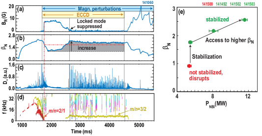
Fig.4 documents the effect of locked islands and their stabilization on . A rotating =1 island appears at 1460 ms (Fig.4d). As a result, and in spite of the Neutral Beam Injection (NBI) heating power being increased (not shown), decreases, and keeps decreasing after the island locks (Fig.4b). ECCD, however, stabilizes the island (Fig.4a) and leads to high values of normalized pressure: for the same amount of NBI (5 MW), drops as low as 1.1 after locking and grows as high as 2.2 after stabilization (Fig.4b). As mentioned, locked mode stabilization also re-establishes the H-mode, as indicated by the presence of Edge Localized Modes in Balmer-alpha emission (, Fig.4c). The H-mode is maintained for as long as the ECCD is deployed, and is lost after the ECCD is turned off and the mode reappears (Fig.4a,c).
Note that the locked =1 island is really suppressed, not unlocked: after the loss of locked mode signal in Fig.4a, no rotating 2/1 island reappears in Fig.4d for as long as ECCD is deployed at the island location. The very fact that the pressure becomes high again, however, may lead to other pressure-driven, pressure-limiting instabilities appearing elsewhere in the plasma. A common example is the rotating 3/2 island in Fig.4d. Without that, might have reached even higher values, or at a lower “cost” in terms of NBI power (2.4 MW earlier in the same discharge, before any island had appeared). The stabilization of the rotating 3/2 island is well established c9 ; c19 , and goes beyond the scope of the present work.
Finally, Fig.4e indicates that, for sufficiently high NBI heating power, locked-mode-controlled discharges attain values of as high as 2.6 without terminating in disruptions. Equivalent discharges with uncontrolled locked modes disrupt at low NBI power and as low as 0.9. Note that values of 2.6 were obtained in the past in discharges not subject to locked modes c28 .
In summary, applied non-axisymmetric magnetic perturbations were used to control the phase of locking of an initially rotating magnetic island. This permitted Electron Cyclotron Current Drive stabilization of the locked island, which avoided the plasma disruption and re-established the high confinement (H) mode.
It is important to note that the technique makes use of static magnetic perturbations that need to penetrate in the plasma on a relatively benign timescale. The estimated locked mode growth-rate in ITER (1.1cm/s, with saturation at up to 35-40 cm) c13 and slowdown time before locking (4 s) give ample time for an externally applied static field to penetrate through walls that, in ITER, will have an =1 resistive time of 190 ms. As a consequence it should be possible to apply the desired =1 static perturbation by means of error-field-correction coils external to the vessel. This permits dedicating the internal coils to tasks needing proximity to the plasma and/or fast response, such as controlling edge localized modes and vertical instabilities.
This material is based upon work supported by the U.S. Department of Energy, Office of Science, Office of Fusion Energy Sciences, using the DIII-D National Fusion Facility, a DOE Office of Science user facility, under Awards DE-SC0008520 and DE-FC02-04ER54698. DIII-D data shown in this paper can be obtained in digital format by following the links at https://fusion.gat.com/global/D3D_DMP. The help of H. Reimerdes in programming the neutral beam injection is gratefully acknowledged, as are fruitful discussions with R. Buttery, R. Groebner and J. Hanson.
.1
.1.1
References
- (1) The ITER Physics Basis, Nucl. Fusion 47, S1-S413 (2007).
- (2) De Vries P.C. et al., Survey of disruption causes at JET, Nucl. Fusion 51, 053018 (2011).
- (3) Sykes A. and Wesson J.A., Major Disruptions in Tokamaks, Phys. Rev. Lett. 44, 1215-1218 (1980)
- (4) Cook I., Materials research for fusion energy, Nature Materials 5, 77-80 (2006).
- (5) Morris A.W., Hender T.C., Hugill J., Haynes P.S., Johnson P.C., Lloyd B., Robinson D.C., Silvester C., Arshad S., and Fishpool G.M., Feedback stabilization of disruption precursors in a tokamak, Phys. Rev. Lett. 64, 1254 (1990)
- (6) Gantenbein G. et al., Complete Suppression of Neoclassical Tearing Modes with Current Drive at the Electron-Cyclotron-Resonance Frequency in ASDEX Upgrade Tokamak, Phys. Rev. Lett. 85, 1242-1245 (2000)
- (7) Maraschek M. et al., Enhancement of the Stabilization Efficiency of a Neoclassical Magnetic Island by Modulated Electron Cyclotron Current Drive in the ASDEX Upgrade Tokamak, Phys. Rev. Lett. 98, 025005 (2007)
- (8) Classen I.G.J. et al., Effect of Heating on the Suppression of Tearing Modes in Tokamaks, Phys. Rev. Lett. 98, 035001 (2007)
- (9) De Lazzari D. and Westerhof E., On the merits of heating and current drive for tearing mode stabilization, Nucl. Fusion 49 075002 (2009). See also Erratum, Nucl. Fusion 50, 079801 (2010)
- (10) Morris A.W., Edwards A.M., Hender T.C. et al., Control of Error-Field and ELMs in ITER-shaped Plasmas in COMPASS-D, IAEA Conf. on Plasma Phys., Vol.1, p.365 (1994)
- (11) Westerhof E., Lazaros A., Farshi1 E., de Baar M.R., de Bock M.F.M., Classen I.G.J., Jas[ers R.J.E., Hogewij G.M.D., Koslowski H.R., Krämer-Flecken A., Liang Y., Lopes Cardozo N.J. and Zimmermann O., Tearing mode stabilization by electron cyclotron resonance heating demonstrated in the TEXTOR tokamak and the implication for ITER, Nucl. Fusion 47, 85 (2010)
- (12) Yu, Q., Günter S., Locking of neoclassical tearing modes by error fields and its stabilization by RF current, Nucl. Fusion 48, 065004 (2008)
- (13) Volpe F.A.G., Austin M.E., La Haye R.J., Lohr J., Prater R., Strait E.J., and Welander A.S., Advanced techniques for neoclassical tearing mode control in DIII-D, Phys. Plasmas 16, 102502 (2009)
- (14) Hollmann E.M. et al., Status of research toward the ITER disruption mitigation system, Phys. Plasmas 22, 021802 (2015)
- (15) La Haye, R.J. et al., Cross-machine benchmarking for ITER of neoclassical tearing mode stabilization by electron cyclotron current drive, Nucl. Fusion 46, 451 (2006)
- (16) La Haye, R.J., Isayama A. and Maraschek M., “Prospects for stabilization of neoclassical tearing modes by electron cyclotron current drive in ITER”, Nucl. Fusion 49, 045005 (2009).
- (17) Ramponi G., Lazzaro E. and Nowak S., On the stabilization of neoclassical tearing modes by electron cyclotron waves, Phys. Plasmas 6, 3561 (1999).
- (18) Volpe F., Sensitivity of ITER ECRH Upper Launcher to Steering Errors and Changes of Profiles and Integration with Equatorial Launcher, J. Phys.: Conf.Ser. 25, 283 (2005)
- (19) Esposito B, et al., Disruption Avoidance in the Frascati Tokamak Upgrade by Means of Magnetohydrodynamic Mode Stabilization Using Electron-Cyclotron-Resonance Heating, Phys. Rev. Lett. 100, 045006 (2008)
- (20) Esposito B. et al., Disruption Control on FTU and ASDEX Upgrade with ECRH, Nucl. Fusion 49, 065014 (2009)
- (21) La Haye R.J., Neoclassical Tearing Modes and their control, Phys. Plasmas 13, 055501 (2006).
- (22) Shiraki D., La Haye R.J., Logan N., Strait E.J., F.A. Volpe F.A., Error Field Detection in DIII-D by Magnetic Steering of Locked Modes, Nucl. Fusion, 54, 033006 (2014)
- (23) Luxon J.L., A design retrospective of the DIII-D tokamak, Nucl. Fusion 42, 614 (2002)
- (24) Strait E.J., Magnetic diagnostic system of the DIII-D tokamak, Rev. Sci. Instrum. 77, 023502 (2006)
- (25) La Haye R.J., Paz-Soldan C., Strait E.J., Lack of Dependence on Resonant Error Field of Locked Mode Island Size in Ohmic Plasmas in DIII-D, Nucl. Fusion 55, 023011 (2015)
- (26) Prater R., Heating and current drive by electron cyclotron waves, Phys. Plasmas 11, 2349 (2004)
- (27) Chang Z. and Callen J.D., Global energy confinement degradation due to macroscopic phenomena in tokamaks, Nucl. Fusion 30, 219 (1990)
- (28) Wagner F. et al., Regime of Improved Confinement and High Beta in Neutral-Beam-Heated Divertor Discharges of the ASDEX Tokamak, Phys.Rev.Lett. 49, 1408 (1982)
- (29) Strait E.J. et al., Wall Stabilization of High Beta Tokamak Discharges in DIII-D, Phys. Rev. Lett. 74, 2483 (1995)
- (30) La Haye R.J., Politzer P.A. and Brennan D.P., Beta limit due to m/n = 2/1 tearing mode onset in the DIII-D hybrid scenario, Nucl. Fusion 48, 015005 (2008).