Spatial interference of light: transverse coherence and the Alford and Gold effect
Jefferson Flórez,1,∗ Juan-Rafael Álvarez,1 Omar Calderón-Losada,1 Luis-José Salazar-Serrano,1,2 and Alejandra Valencia1
1Laboratorio de Óptica Cuántica, Universidad de los Andes, A.A. 4976, Bogotá, D.C., Colombia
2ICFO-Institut de Ciencies Fotoniques, Mediterranean Technology Park, 08860 Castelldefels, Barcelona, Spain
∗j.florez34@uniandes.edu.co
Abstract
We study the interference between two parallel-propagating Gaussian beams, originated from the same source, as their transverse separation is tuned. The interference pattern as a function of such separation lead us to determine the spatial coherence length of the original beam, in a similar way that a Michelson-Morley interferometer can be employed to measure the temporal coherence of a transform limited pulse. Moreover, performing a Fourier transform of the two-beam transverse plane, we observe an intensity modulation in the transverse momentum variable. This observation resembles the Alford and Gold Effect reported in time and frequency variables so far.
OCIS codes: (260.3160) Interference; (030.1640) Coherence; (230.5440) Polarization-selective devices.
References and links
- [1] J. W. Goodman, Statistical Optics (John Wiley & Sons, Inc., 2000).
- [2] X. Y. Zou, T. P. Grayson, and L. Mandel, “Observation of quantum interference effects in the frequency domain,” Phys. Rev. Lett. 69, 3041 (1992).
- [3] L. Mandel, “Interference and the Alford and Gold Effect,” J. Opt. Soc. Am. 52, 1335 (1962).
- [4] W. P. Alford and A. Gold, “Laboratory Measurement of the Velocity of Light,” Am. J. Phys. 26, 481 (1958).
- [5] M. P. Givens, “Photoelectric Detection of Interference between Two Light Beams Having a Large Path Difference,” J. Opt. Soc. Am. 51, 1030 (1961).
- [6] L. J. Salazar-Serrano, A. Valencia, and J. P. Torres, “Observation of spectral interference for any path difference in an interferometer,” Opt. Lett. 39, 4478 (2014).
- [7] L. J. Salazar-Serrano, A. Valencia, and J. P. Torres, “Tunable beam displacer,” Rev. Sci. Instrum. 86, 033109 (2015).
- [8] B. Redding, M. A. Choma, and H. Cao, “Spatial coherence of random laser emission,” Opt. Lett. 36, 3404 (2011).
- [9] P. Barcik, and L. Hudcova, “Measurement of Spatial Coherence of Light Propagating in a Turbulent Atmosphere,” Radioengineering 22, 341 (2013).
- [10] B. E. A. Saleh, A. F. Abouraddy, A. V. Sergienko, and M. C. Teich, “Duality between partial coherence and partial entanglement,” Phys. Rev. A 62, 043816 (2000).
- [11] J. C. Diels, and W. Rudolph, Ultrashort Laser Pulse Phenomena (Academic Press, Inc., 1995).
- [12] M. O. Scully, and M. S. Zubairy, Quantum Optics (Cambridge University Press, 1997).
1 Introduction
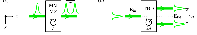
Interference of coherent light occurs if there is a non-random phase difference between two or more beams. For example, in a Michelson-Morley (MM) or in a Mach-Zender (MZ) interferometer, the two-beam relative phase is introduced by means of a path difference between the interferometer arms. The variation of this path difference allows to tune the temporal delay between the beams, as shown in Fig. 1(a), resulting in an interference pattern when the interferometer output intensity is observed as a function of the temporal delay. For these interferometers, the maxima and minima on the intensity appear if the temporal delay is less or approximately equal to the temporal coherence of the light source, which in turn can be used to quantify its coherence time if we are dealing with a transform-limited pulse [1]. Furthermore, it is interesting to notice that interference can be observed as well by performing a spectral analysis of the output electric field [2]. In this second case, a periodic modulation on the output intensity is obtained as a function of the frequency variable for a fixed temporal delay that is greater than the coherence time of the source. The latter fact was named as the Alford and Gold Effect (AGE) by L. Mandel [3], originally measured by W. P. Alford and A. Gold [4], and expressed in terms of light interference by M. P. Givens [5]. The AGE has been observed for single photons [2] and for a pulsed laser [6] using a MM interferometer.
Apart from the temporal domain, interference can also be observed in the spatial variables. For example, in the Young’s double-slit experiment, the separation between the two slits must be less or approximately equal to the spatial coherence length of the light source in order to observe a bright and dark fringe pattern [1]. Indeed, the fringe visibility of a double-slit interferometer gives a measure of the degree of spatial coherence for a finite-size light source [8, 9]. Although the Young’s double-slit experiment is the usual choice to determine the spatial coherence of light, one may think on an alternative approach analogous to the way in which temporal coherence is quantified via a MM interferometer. In this paper, we achieve this goal by using a tunable beam displacer (TBD) similar to the one reported in [7]. A TBD is a device that splits a light beam into two parallel-propagating beams, each one shifted by a tunable transverse distance with respect to the incoming beam, as shown in Fig. 1(b). The capability of tuning the separation between the two beams allows us to observe a spatial interference pattern as a function of , and therefore to have an analogous to the MM interference pattern as a function of the temporal delay. Additionally, by measuring the TBD output intensity at the Fourier plane, we observe a periodic intensity modulation similar to the temporal AGE with light pulses [5, 6]. The experimental results are in agreement with a direct correspondence between the temporal and spatial interference patterns measured by means of a MM or a MZ interferometer and a TBD device, respectively.
2 Theory
To put on solid ground the analogy between the TBD and the MM interferometer, let us consider the situation depicted in Fig. 1(b), in which a monochromatic, diagonally polarized, well-collimated Gaussian beam enters to the TBD. The transverse momentum distribution for this incident beam is given by a Gaussian function centered at ,
| (1) |
where is the beam waist. Then, the transverse component of the electric field in position variables of such a beam, corresponds to the Fourier transform of , and is equal to
| (2) |
with the electric field amplitude, the polarization vector chosen to be diagonal, and the conjugate vector of the transverse momentum . In the last expression, we have taken since we are only interested in fields shifted along the -direction. Note that the factor comes from considering a small beam deviation in the -direction with respect to the -axis, which is defined perpendicular to the TBD input plane [10].
At a fixed transverse plane after the TBD, the total electric field is proportional to the superposition of two fields shifted by distances and , respectively. This is
| (3) |
where is a relative phase between the two fields that appears due to the working principle of the TBD. The total intensity is then given by
When one is interested in the temporal coherence and uses a MM interferometer to measure it, one must integrate the total intensity with respect to time since the detectors are not fast enough to resolve the temporal changes on such intensity [11]. Spatially, we proceed in an analogous fashion by integrating the total intensity over the detection area . Following this, the integrated intensity reads
| (4) |
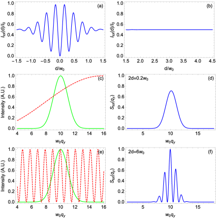
From Eq. (4), one recognizes the usual interference pattern of partially coherent beams mediated by the transverse displacement . In analogy with the temporal interference in a MM interferometer, the Gaussian factor accompanying the cosine function is proportional to the degree of spatial coherence of the source [12]. It is then possible to recognize as the corresponding spatial coherence length. In particular, if is smaller or approximately equal to , the interference is revealed as an intensity modulation governed by the product of the cosine function and an envelope given by the Gaussian term. In contrast, if is greater than , one gets a constant total intensity equal to since the exponential function vanishes. We represent these behaviors in Figs. 2(a) and 2(b), respectively. A negative distance in Fig. 2(a) means that the lower beam after the TBD in Fig. 1(b) has moved to the upper position, and the contrary for the other outcome of the TBD. The minimum in the same Fig. appears for due to internal reflections inside the TBD, which leads to .
Apart from observing the spatial interference, the TBD also allows to measure the spatial AGE. To observe this formally, one needs to calculate the intensity at the Fourier plane, where is the Fourier transform of the total electric field magnitude,
| (5) |
Since the effects of the TBD will only be observed in the -direction, we take , so that becomes
| (6) |
with , and given by Eq. (1).
Observing Eq. (6), one notices again an intensity modulation of mediated by the cosine function, but in the conjugate variable . In particular, if the period of oscillation of the cosine function is greater than the width of (Fig. 2(c)), there is no modulation, as depicted in Fig. 2(d). In contrast, if (Fig. 2(e)), there is a modulation of the incoming beam momentum distribution, as shown in Fig. 2(f).
Concretely, from Figs. 2(d) and 2(f), we can see that as grows and becomes greater than , a set of oscillations appear within the Gaussian envelope . This means that even if the two gaussian beams are far enough from each other in such a way that there is no interference pattern in the position variable, they do display an intensity modulation at the Fourier plane, revealing a spatial analogous to the AGE.
3 Experimental implementation and Results
To test the previous theory, we implemented the experimental setup shown in Fig. 3. Using a 808 nm-CW laser (Thorlabs, CPS808), we prepared with mm by means of a single mode fiber, and set the polarization of the beam to be diagonal by means of a polarizer (Pol. 1.) The TBD consisted of a polarizing beamsplitter (PBS), two mirrors (M3 and M4) mounted on a rotational stage, and a polarizer at (Pol. 2) to have the two output beams with the same polarization and intensity, as shown in the inset of Fig. 3. The mirrors M0, M1, and M2 are placed in order to have both the TBD input and output along the -direction.
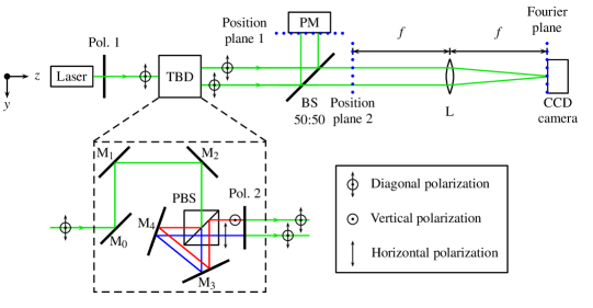
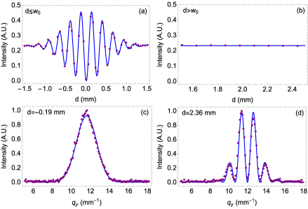
In order to observe the total intensity in the position variable and in its conjugate at the same time, we placed a 50:50 beam splitter and measured in its reflection the intensity in position , and in its transmission the intensity in momentum, . The measurement in the position variable was done using a power meter (Coherent, BeamMaster-USB BM-7 Si-Enhanced), at what we call the Position plane 1. The results of this measurement are shown in Fig. 4(a) and 4(b), for and , respectively. In Fig. 4(a), a typical interference pattern is clearly observed as a function of the separation . By fitting the data to Eq. (4), the full width at half maximum (FWHM) of the gaussian envelope is mm, indicating the spatial coherence length of our light source. This result is in agreement with the expected theoretical value . In sharp contrast, Fig. 4(b) shows no interference, represented as a flatline. The continuous lines in Fig. 4(a) and 4(b) correspond to the ones depicted in Fig. 2(a) and 2(b) for the theoretical model, respectively, and demonstrate that it is possible to observe an interference pattern spatially analogous to the one obtained in a MM interferometer.
The measurement of was done using a 2-system composed by a biconvex lens of focal length cm, and placing a CCD camera (SBIG, ST-1603ME) at the Fourier plane. The 2-system transforms the position variables, in what we call Position plane 2, into the corresponding conjugate ones. In the Fourier plane there is a one-to-one correspondence between and the coordinate at the Fourier plane, given by , with denoting the wavelength of the light beam. The experimental results are shown in Fig. 4(c) and 4(d) for and , respectively. From Fig. 4(c), it is observed that at the Fourier plane there is no intensity modulation for close to zero, retrieving , as expected. However, in Fig. 4(d) there is a modulation of . These observations are analogous to the AGE reported in temporal variables so far, and exhibit a similarity between the temporal and spatial degrees of freedom of light. It is interesting to notice that the center of both Figs. 4(c) and 4(d) is mm-1, indicating that this is the value of in Eq. (2). Physically, this value is related to a small deviation of the incoming beam with respect to -axis, given by an angle . Using our measured , we get mrad.
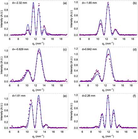
As complementary measurements, we report in Fig. 5, the intensity at the Fourier plane for various separations between the beams. From these graphs, one observes how the modulation of varies according to the separation between the beams and sees that when increases, the number of peaks increases as well.
4 Conclusions
We have performed and observed interference of light in its spatial degree of freedom. This was done using a tunable beam displacer that allowed us to recreate in the spatial domain an interferometer analogous to the Michelson-Morley. In this way, we were able to measure the spatial coherence length of a light beam, and to observe the spatial Alford and Gold effect. Using the fact that there is a correspondence between the temporal and spatial degrees of freedom of light, our results open the door to new interferential experiments recreating the results obtained in the temporal regime.
Acknowledgments
We acknowledge useful discussions with David Guzmán. This work was supported by Facultad de Ciencias, Universidad de los Andes, Bogotá, Colombia, under project number P15.160322.009/01-02-FISI06.