Frequency tuning of a triply-resonant whispering-gallery mode resonator to MHz wide transitions for proposed quantum repeater schemes
Abstract
Quantum repeaters rely on interfacing flying qubits with quantum memories. The most common implementations include a narrowband single photon matched in bandwidth and central frequency to an atomic system. Previously, we demonstrated the compatibility of our versatile source of heralded single photons, which is based on parametric down-conversion in a triply-resonant whispering-gallery mode resonator, with alkaline transitions [Schunk et al., Optica 2, 773 (2015)]. In this paper, we analyze our source in terms of phase matching, available wavelength-tuning mechanisms, and applications to narrow-band atomic systems. We resonantly address the D1 transitions of cesium and rubidium with this optical parametric oscillator pumped above its oscillation threshold. Below threshold, the efficient coupling of single photons to atomic transitions heralded by single telecom-band photons is demonstrated. Finally, we present an accurate analytical description of our observations. Providing the demonstrated flexibility in connecting various atomic transitions with telecom wavelengths, we show a promising approach to realize an essential building block for quantum repeaters.
I Introduction
Much progress has been achieved in the development of sources of quantum light. A source for which both central wavelength and bandwidth can be adapted to the optical transitions of e.g. single atoms Specht2011 , atomic ensembles Hald1999 ; Hammerer2005 , optomechanical resonators Aspelmeyer2014 , or quantum dots will give new prospects for a plethora of fundamental studies. Efficient photon-atom coupling paves the way for atom-based quantum memories Lvovsky2009 ; Simon2010 , super-radiance of collectively excited atoms R.H.Dicke1953 , two-photon spectroscopy Jechow2013 , and efficient photon-atom interaction either in free space Fischer or in an optical cavity Ourjoumtsev2011a .
Single photons from trapped atoms Legero2004 ; Volz2006 ; Beugnon2006 ; Maunz2007 ; Maiwald2012 , single molecules Siyushev2014 , rare earth ions in a crystal Utikal2014 , semiconductor quantum dots Akopian2011 , four-wave mixing in a cloud of cold atoms Leong2015 , and cavity-assisted parametric down-conversion (PDC) Bao2008 ; Wolfgramm2011 ; Fekete2013 ; Lenhard2015 ; Brecht2015 ; Schunk2015a were demonstrated as promising candidates for photon-atom interactions. PDC has the technological advantage to not require an evacuated environment or cryostatic temperatures. At the single photon level PDC allows for one pump photon to split up into one pair of signal and idler photons. Nearly single-photon functionality of such a source is achieved by heralding: a single-photon detection event in e.g. the idler mode results in a heralded single photon in the signal mode. In general, the heralding removes the vacuum component from the bipartite state also for non-photon-number-resolving click detection.
Optical resonators can be used to control the phase matching conditions Dunn1999 , to increase the conversion efficiency, and to reduce the bandwidth of the generated photons. We implement such an optical parametric oscillator (OPO) as a triply-resonant whispering-gallery mode resonator (WGMR), which confines light via total internal reflection. The small mode volumes, high quality factors, and the wavelength independent nature of total internal reflection make WGMRs an excellent platform for nonlinear optics (Savchenkov2004, ; Del'Haye2007, ; Furst2010natural, ; Furst2010, ; Lin2013, ). Evanescent field coupling allows to tune the pair generation rate and bandwidth of the generated photon pairs Gorodetsky1999 . Lithium niobate is a suitable host material due to its high nonlinearity and the possibility to achieve natural phase matching Furst2010natural . Around the absorption minimum at a wavelength of , the intrinsic losses of lithium niobate and hence the minimal photon bandwidth can be as small as or , respectively Leidinger2015a . For our investigated parametric wavelengths (approximately ) a minimal bandwidth of a few was observed.
Previously, we have reported on a parametric WGMR source of bright squeezed light Furst2011 and narrowband photon pairs Michael2013 compatible to atomic transitions Schunk2015a . In this paper, we discuss the technical details crucial for the implementation and further development of such a source and explain its underlying principles. In the first part of the paper, we present our experimental scheme followed by an analysis of stepwise and continuous frequency tuning. We achieve continuous tuning of the parametric frequencies on the MHz scale with a movable dielectric substrate. Continuous tuning is used to match the parametric wavelength to the D1 lines of rubidium and cesium Schunk2015a . The shown stability of the signal frequency is comparable to the linewidth of the atomic transition. In a below-threshold experiment, we observe photons generated from atomic fluorescence that are heralded by idler parametric photons Schunk2015a , for which we present a full analytic description.
II Characterization of PDC in a triply-resonant WGMR
II.1 Phase matching
In this section we describe parametric interaction between three resonant fields in a WGMR.
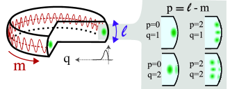
Solving Maxwell’s equation for a dielectric spheroid, one obtains the eigenmodes of the WGMR. These eigenmodes are characterized by three integer numbers: the polar mode number , the azimuthal mode number , and the radial mode number . The angular mode number is additionally introduced to simplify the discussion of modes mostly used in the experiment (see Fig. 1). The fundamental mode () shows in good approximation a Gaussian transversal profile with a single intensity maximum.
The eigenfrequencies of the system are defined by the dispersion relation Oraevsky2002 ; Gorodetsky2006 , which connects the mode numbers , q, and p with the resonance frequency :
| (1) |
where p and are of the order of one. The WGMR radius and rim curvature are given by and , respectively. The speed of light in vacuum is . The parameter is 1 for TE modes and for TM modes, where the electric field is mainly orthogonal polarized for TE modes and mainly parallel polarized for TM modes with respect to the WGMR equatorial plane. The wavelength-dependent refractive index of the WGMR is . The q-th root of the Airy function can be approximated as .
Phase matching of PDC in a triply-resonant WGMR requires energy conservation:
| (2) |
expressed in terms of the oscillation frequencies of the electric fields, and momentum conservation Kozyreff2008 ; Furst2010natural :
| (3a) | ||||
| (3b) | ||||
| (3c) | ||||
expressed in terms of the azimuthal mode numbers and the angular mode numbers . The subscripts p, s, and i denote pump, signal, and idler, respectively. In case of , the phase matching conditions given by Eq. 3 can be conveniently approximated by the waveguide phase matching condition:
| (4) |
introducing the effective refractive index , which includes geometric dispersion to the refractive index. The azimuthal mode numbers follow from Eq. 1.
In general, the cavity resonances of signal and idler determine the frequency intervals in which electric fields can be excited by the PDC process (see Fig. 2). The cavity resonances for pump, signal, and idler intensities are well approximated by Lorentzian functions:
| (5) |
The respective frequency detuning gives the normalized difference between the mode resonance frequency and the actual electric field frequency exciting the mode. The respective bandwidth is the sum of coupling rate to the WGMR and loss rate in the WGMR. The coupling ratio gives the coupling scenario of the respective mode, i.e under-coupled for , critically coupled for , and over-coupled for .
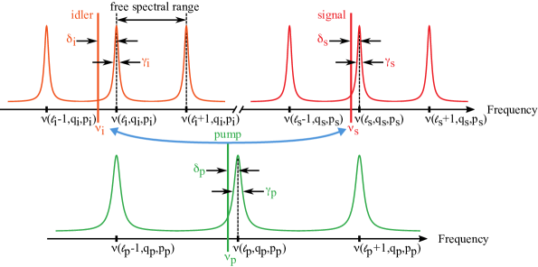
The PDC frequency mismatch:
| (6) |
is the residual mismatch between the pump electric field frequency and the parametric resonance frequencies normalized to the mean bandwidth of signal and idler. In case of zero PDC mismatch, energy conservation (see Eq. 2) allows for a highly efficient conversion from the pump electric field frequency to the exact parametric resonance frequencies . In a typical experiment, the pump laser frequency is locked to the resonance frequency of the pump mode () for a high intra-cavity power. The PDC frequency mismatch is then controlled via the temperature-dependence of the resonance frequencies .
The system exhibits a threshold with respect to the external pump power : bright parametric beams are generated when the parametric gain exceeds the respective losses of signal and idler. This oscillation threshold is given by Debuisschert1993 ; Richy1994 ; Breunig2013b :
| (7) |
In case of zero PDC mismatch () and zero pump detuning (), the minimal threshold is reached, which is typically of the order of a few in our system Furst2010 . depends on the signal and the idler bandwidth, the coupling of the pump laser to the pump mode, the spatial overlap of pump, signal, and idler modes, and the nonlinearity coefficient, which we treat as constants in the following.
Far below the OPO threshold and in the limit of low gain, the rate of photon pair production in the resonator is given by:
| (8) |
The coupling ratio introduced above defines the escape probability for signal and idler photons from the resonator. The signal rate, the idler rate, and the pair generation rate outside the resonator are given by , , and , respectively.
Energy conservation does not result into monochromatic frequencies of signal and idler photons even in case of a monochromatic pump. In case of zero pump detuning, zero PDC mismatch, and equal bandwidths of signal and idler, the photons are generated over the full bandwidth of the respective modes Ou1999 ; predojevic2015engineering .
Above the OPO threshold and in case of a monochromatic pump, bright signal and idler beams are generated at monochromatic frequencies. The so-called oscillation condition sets a joint frequency detuning for signal and idler, which is connected to the PDC frequency mismatch as . The signal/idler output power is given by Debuisschert1993 ; Richy1994 ; Breunig2013b :
| (9) |
In an experiment, the pump laser has a finite linewidth, which is typically much narrower than the bandwidths of the mode triplet. In this case, the linewidth of the parametric beams is determined by the linewidth of the pump.
II.2 Experimental scheme
In this section we describe our experimental scheme for generation of non-classical light with PDC in a triply-resonant WGMR.
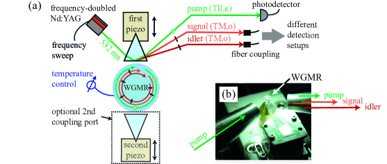
In the experiment (see Fig. 3 and Ref. Furst2010natural ; Furst2010 ; Michael2013 ; Schunk2015a ) we use a WGMR made of MgO-doped () lithium niobate, which is manufactured by single point diamond turning and polishing techniques. For PDC, we pump the resonator with a frequency-doubled Nd:YAG laser (Prometheus, Innolight) at a wavelength of , whose frequency detuning is measured by a Fabry-Pérot interferometer. The WGMR radius and rim curvature are and , respectively. We employ evanescent prism coupling Gorodetsky1999 to excite the pump mode and to couple the parametric beams to free space. The temperature of the WGMR is measured with a thermistor and stabilized with a proportional-integral-derivative controller at the millikelvin scale.
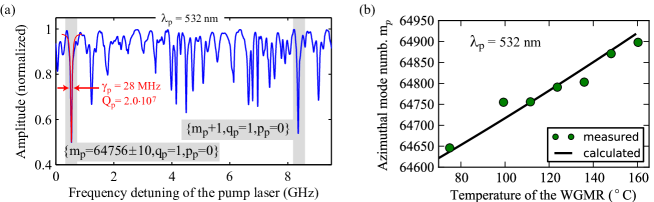
From the analysis of the spectral positions and far-field patterns of the pump modes,we identify the mode numbers as described in Ref. Schunk2014a . The frequency spectrum in Fig. 4(a) is measured at a WGMR temperature of . For this spectrum, the analysis yields an azimuthal mode number for the fundamental pump mode.
For higher WGMR temperatures, the product of WGMR radius and refractive index increases since thermal refraction Schlarb1994 and thermal expansion Weis1985 are both positive functions in case of lithium niobate. Keeping the frequency sweep range of the laser fixed, this temperature induced change of refractive index leads to a coupling of the pump laser to modes with higher azimuthal mode numbers m according to Eq. 1. In Fig. 4(b) the measured azimuthal mode number of a fundamental pump mode is shown at various temperatures together with the calculated values.
Phase matching in the WGMR depends on the refractive indices of the host material. In the degenerate case (), the effective refractive indices of all three modes have to be equal, which follows from Eq. 4. To fulfill these conditions for three resonator modes, material dispersion must be compensated. We achieve this with natural phase matching of type-I PDC in a z-cut configuration of the lithium niobate crystal where the optic axis is aligned along the symmetry axis of the resonator Furst2010natural . We pump the extraordinarily polarized TE modes of the WGMR, while the parametric light is generated in the ordinarily polarized TM modes. Due to the negative birefringence of lithium niobate, where the refractive index for the ordinary axis is higher than for the extraordinary axis, refractive index matching and therefore phase matching can be fulfilled. This concept extends to the case of non-degenerate PDC ().
We use the fundamental mode for pumping the resonator. In principle, all eigenmodes with significant coupling (see Fig. 4(a)) can be used for PDC. However, a conversion from a fundamental pump to fundamental parametric modes exhibits the lowest minimal threshold given by Eq 7 Furst2010 . In terms of the generated wavelength, this fundamental conversion channel is well separated from other conversion channels with higher radial or angular modes (see Sec. II.3). This separation is beneficial for single mode operation of the photon pair source (Michael2014, ).
II.3 Selecting mode triplets by temperature
In this section we discuss phase matching of PDC in WGMRs for the various mode combinations. Whispering gallery modes are guided almost entirely within the dielectric via total internal reflection. The wavelength-independent nature of total internal reflection allows pump, signal, and idler to be resonantly enhanced (triply-resonant OPO). This narrows down the phase matching conditions based on the small parametric bandwidths and the condition of momentum conservation. PDC in bulk lithium niobate is highly tunable by changing the crystal temperature. In the following, we explain how the discrete PDC spectrum in a WGMR can also be tuned via this temperature dependence.
The basic principle behind natural phase matching in a triply-resonant WGMR is explained in Fig. 5. The temperature-dependent resonance frequencies of different azimuthal pump, signal, and idler modes are depicted as solid green, red, and orange lines, respectively. The radial mode numbers and angular mode number for pump, signal, and idler, respectively, are the same for different azimuthal modes. As an illustration of energy conservation given by Eq. 2, we show the sum of the signal and idler resonance frequencies as purple dashed lines. Energy conservation in the case of zero detuning (, cf. Fig. 2) is fulfilled at the intersection of any purple dashed line with any solid green line. Phase matching is only found when the azimuthal mode numbers of signal and idler add up to the azimuthal mode number of the pump, which is the first condition of momentum conservation given by Eq. 3(a).
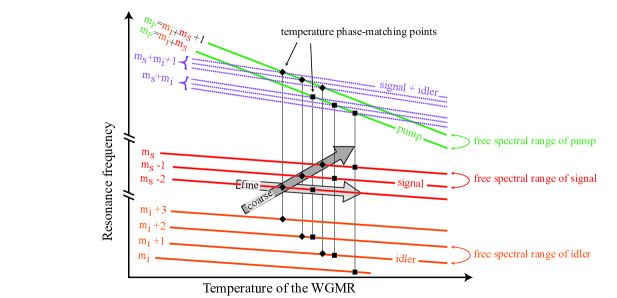
There are two methods to tune the azimuthal mode frequency by temperature. The first method is to select a specific pump mode and to track it with the pump laser while changing the resonator temperature. The azimuthal mode numbers and of signal and idler, respectively, will change in unity steps (). The second method is to change the azimuthal pump mode’s number by unity steps, , and adjust the temperature to restore the phase matching for a selected (e.g., signal) mode . This leads to unity steps of the idler mode, , while remains unchanged.
In an experiment, the first method is more intuitive since it requires only slight changes in the pump laser frequency following the temperature-dependent frequency shift of the pump mode. The second method starts with a significant change in the pump laser frequency by one free spectral range. Subsequently, a searching of the initial signal azimuthal mode via the first tuning method is required. For this, the frequency of the generated signal can be used as an observable.
For our experiment, the first method provides a coarse tuning (see Fig. 6) for the signal and idler frequency in steps of and , respectively. This corresponds approximately to the respective free spectral ranges. The second method enables fine tuning (see Fig. 3(a) in Ref. Schunk2015a ) of either the signal frequency in steps of with a constant or the idler frequency in steps of with a constant . In both cases these steps are considerably smaller than the free spectral ranges.
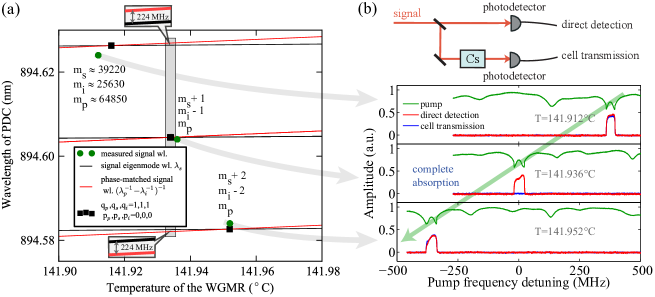
The temperature-dependent phase matching pertaining to our experiment is shown in Fig. 6. In (a), the calculated resonance wavelength of the fundamental signal mode is shown together with the signal wavelength found from energy conservation given by Eq. 2. The resonance wavelengths of the pump and the idler are given by , respectively. PDC occurs for a triplet of modes fulfilling the momentum conservation conditions (see Eq. 1(a)-(c)), only when the phase-matched signal frequency intersects with an actual WGMR resonance frequency (cf. Fig. 5).
A frequency sweep over the fundamental pump mode and the generated signal above threshold is shown in Fig. 6(b) for three different temperatures. The resonance frequencies of the modes change continuously with temperature, whereas PDC is only generated for distinct temperature and pump frequency combinations (see Fig. 5 and Fig. 6). The non-Lorentzian pump resonance is well described by additional losses caused by the parametric process Breunig2013b . As shown in Fig. 6(a), individual steps originate from stepwise changes in the azimuthal mode number of signal and idler (cf. Fig. 5), keeping the pump laser frequency locked to the fundamental mode.
In doubly-resonant waveguides (cf. Fig. 2 in Ref. Brecht2015 ), a simultaneous excitation of various azimuthal modes of signal and idler separated by multiple free spectral ranges is still possible below threshold. In our triply-resonant case, this is prevented by the momentum conservation condition given by Eq. 3. However, when one PDC channel is fully resonant (PDC frequency mismatch ), an unwanted generation of PDC to the adjacent azimuthal signal and idler modes is possible below the OPO threshold. The corresponding pair generation rates can be estimated for the example depicted in Fig. 6(a). According to Eq. 8, the pair generation rate to a signal and idler mode combination with zero PDC frequency mismatch is 1153 times higher at our minimal photon bandwidth of (see Fig. 13) than the pair generation rate to an adjacent azimuthal signal and idler mode combination with with the calculated mismatch .
All temperature-dependent calculations for our system (Fig. 4(b), Fig. 6, Fig. 7, and Fig. 8) are based on thermorefractivity Schlarb1994 and thermal expansion Weis1985 of lithium niobate. Limited knowledge on the actual MgO concentration of the crystal, the actual temperature at the rim of the resonator, and the uncertainty on temperature induced strain on the resonator, which is glued to a base plate, make it necessary to introduce an additional scaling for the calculations. Therefore, we converted the calculated phase matching temperatures as to match the calculations to the measurement results in the investigated temperature range from , which then agree consistently with the experimental data.
Phase matching depends on many different parameters such as the WGMR temperature, the pump wavelength, the respective mode triplet, the resonator size, and the MgO concentration of lithium niobate, or more generally, on the WGMR host material properties. For planning an experiment, an efficient numerical characterization of the parameter space is required. We have developed an algorithm to examine phase matching for a selected combination of pump, signal, and idler modes with given radial and angular mode numbers and , respectively. The WGMR radius , the rim curvature , the pump wavelength range (approximately one free spectral range, see Fig. 4(a)), and the investigated temperature range are preset. The algorithm is designed to find the exact phase-matched resonance frequencies (zero detuning, ) given by Eq. 1 and WGMR temperature for each combination of the azimuthal mode numbers , constrained by the energy conservation condition given by Eq. 2 and momentum conservation given by Eq. 3.
The algorithm works as follows. First, the approximate phase-matched parametric frequencies are calculated by fixing the WGMR temperature and pump wavelength and treating the azimuthal mode numbers as continuous variables. The algorithm determines the azimuthal mode number of the pump and then varies the azimuthal mode numbers of the signal until energy conservation is fulfilled. The corresponding azimuthal mode numbers of the idler follow from momentum conservation. In a next step the azimuthal mode numbers are rounded to integer numbers while obeying momentum conservation, which results in shifted resonance frequencies . Finally, the resulting energy mismatch is compensated by varying the WGMR temperature to yield the exact phase matching temperatures and resonance frequencies of one phase-matched triplet.
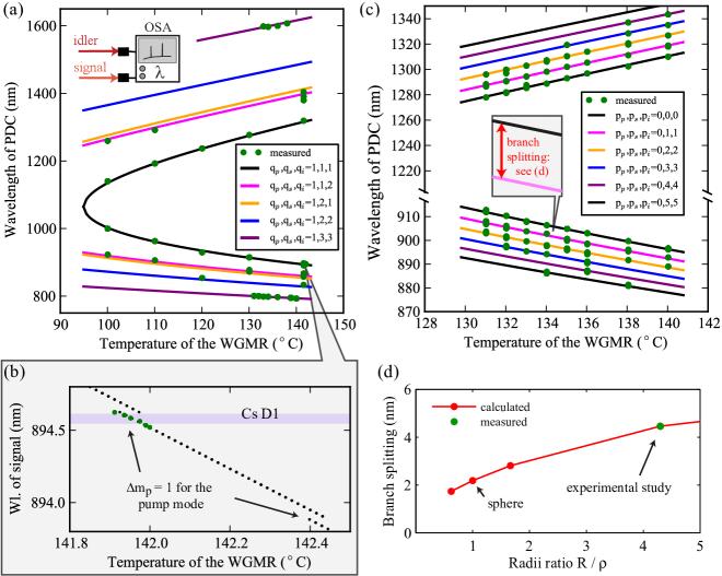
Various PDC conversion channels originating from a fundamental pump mode are presented in Fig. 7 for the temperature ranging from to . Geometric dispersion leads to a drastic change in the emission frequency for the signal and the idler modes with different radial mode numbers in (a) and different angular mode numbers in (c). Each conversion channel in (c) with represents a nearly degenerate cluster of conversion channels generally defined by the cluster number Michael2014 , which are not shown for simplicity.
While changing the temperature, we keep the frequency of the pump within one free spectral range of the resonator (see Fig. 4(a)) due to the constraints on frequency tuning of the pump laser. Hence, the azimuthal mode number of the pump mode has to be changed by one after a certain temperature interval. This results in the two discontinuities shown in Fig. 7(b) (cf. Fig. 4(b)). The conversion to modes with higher radial mode numbers and angular mode numbers needs to be suppressed or filtered out for single-mode operation Michael2014 , which is typically done using standard interference filters with a bandpass window of a few nanometer. The wavelength difference of the fundamental conversion channel to higher order angular conversion channels strongly depends on the curvature of the WGMR (see Fig. 7(d)).
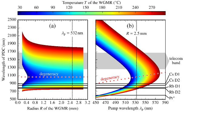
For tuning the parametric wavelengths to various other physical systems we analyze the most efficient conversion channel from a fundamental pump to fundamental signal and idler modes in Fig. 8 in terms of the radius R of the WGMR, the central wavelength of the generated signal and idler, and the temperature of the WGMR. The calculations are performed for a MgO-doped lithium niobate WGMR and a wavelength range of the parametric light where high quality factors can be expected (approximately ) Leidinger2015a . Validity of the Sellmeier equation was tested over a temperature range from to in Ref. Schlarb1994 . Smaller resonators exhibit stronger waveguide dispersion according to the increasing weight of higher-order terms in the dispersion (see Eq. 1). Degenerate signal and idler are already found at room temperature for a WGMR radius of at a pump wavelength of (see Fig. 8(a)) and for a WGMR radius of at a pump wavelength of (see Fig. 8(b)).
The wide tuning range of the generated light from the visible to the near infrared allows for addressing a variety of physical systems indicated in Fig. 8. Especially relevant are those that have natural linewidths at the MHz scale which allows for highly efficient photon coupling. A swapping of the bipartite quantum state of the photon pair to two other physical systems, e.g. an optomechanical cavity Aspelmeyer2014 in a telecom band and a single atom, is possible for specific combinations of WGMR radius and pump wavelength.
II.4 Continuous tuning of the parametric frequencies
In this section we supplement the discussion of the phase matching temperature dependence by a second independent mechanism, which may be realized via the linear electro-optical effect in lithium niobate Guarino2007 ; Michael2013 , by applying external pressure Ilchenko1998 ; Wagner2013 or by perturbing the resonator’s evanescent field Teraoka2006 ; Schunk2015a . This is required to continuously tune the generated signal or idler to an arbitrary frequency, e.g. an atomic transition, with MHz precision. Our concept for continuous tuning starts at a temperature phase matching point with zero PDC frequency mismatch given by Eq. 6. In a second step the temperature of the WGMR is changed, which initially leads to an increased PDC frequency mismatch. This acquired PDC frequency mismatch is then compensated with the second tuning mechanism resulting in phase matching at different frequencies of the modes. In a final step the pump laser frequency is tuned to the new resonance frequency of the same pump mode. In the following, we explain phase matching in case of the two tuning mechanisms and discuss various experimental implementations for the second tuning mechanism.
Continuous tuning of the parametric frequencies with temperature alone is limited to a narrow frequency interval determined by the differential thermal dispersion and bandwidths of the pump, signal, and idler modes. In our case, this frequency interval is of the same order as the bandwidths of the signal and the idler. For a type-0 quasi-phase matched PDC process in lithium niobate, where all three fields are extraordinarily polarized, tuning ranges can exceed the parametric bandwidths by an order of magnitude Werner2015 , because the resonance frequencies of pump, signal, and idler have a similar temperature dependence. The main downside of this method is the change in conversion efficiency (see Eq. 9) due to the temperature-dependent change in the PDC frequency mismatch . Continuous tuning without a change in conversion efficiency can be achieved by amending temperature tuning with a second tuning mechanism independent from temperature.
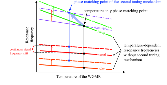
Phase matching in case of two tuning methods is illustrated in Fig. 9. The temperature-dependent resonance frequencies of one triplet of pump, signal, and idler modes are illustrated as bold lines. These modes obey the conditions of momentum conservation given by Eq. 3. Energy conservation in the case of zero detuning is fulfilled at any intersection of the pump frequency with the sum of the signal and the idler frequency (thin purple line), which occurs at exactly one point when only temperature is used for tuning. The second tuning mechanism shifts the resonance frequencies vertically leading to a new phase matching point at a different temperature and different resonance frequencies. In Fig. 9, the pump and the parametric modes are blue shifted. In general other combinations of shifts are possible.
The linear electro-optical effect in lithium niobate Weis1985 has been demonstrated to provide one possibility to tune the resonance frequencies of a monolithic resonator Guarino2007 ; Michael2013 . The refractive index change for signal and idler can be approximated as with a voltage applied over a distance . The electro-optic coefficients in lithium niobate for the pump and the parametric modes are given by and for a voltage applied along the z-direction of the crystal Zgonik2002 .
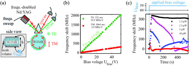
In the experiment illustrated in Fig. 10(a), we study the possibility of electro-optical tuning of PDC by measuring the voltage-induced frequency shifts of the modes with an external laser for the pump (TE, extraordinarily polarized) mode at a wavelength of and for the signal and idler mode (TM, ordinarily polarized) at a wavelength of . We use a resonator made of MgO-doped lithium niobate () of radius , rim curvature , and thickness in this measurement. The top and bottom sides of the resonator are coated with silver. We expect electro-optical tuning rates of and for the pump and the degenerate parametric mode, respectively. The experiment was carried out at room temperature and at the pump power of . The measured electro-optical tuning rates for the pump mode and the parametric mode of and , respectively (see Fig. 10(b)), are reduced by approximately a factor of two compared to the theoretical values. One possible explanation is the fringe field effect, as illustrated in inset of Fig. 10(a). A broadening of the bandwidths due to the conductive coating was not observed in the investigated voltage regime.
It should be pointed out that the electro-optical tuning rates in lithium niobate have the same sign for the TE and TM modes, and their ratio is close to the temperature tuning rates ratio. This limits the utility of the electro-optical tuning as the second mechanism. Moreover, photoconductivity and the onset of a photovoltaic current impedes the linear electro-optical effect Gerson1986 ; Buse1999 at increased green pump powers. Free charges are created within the mode volume leading to a local compensation of the electric field. A similar behavior for the TM-polarized beam at was not observed. For a green pump power of , the effect of an applied voltage already decays at the seconds scale (see Fig. 10(c)). The bandwidth at critical coupling was approximately with of transmitted pump power at the cavity resonance. A use of the electro-optical effect at a wavelenth of is therefore only possible in case of low pump powers or fast switching voltages.
Future studies may also involve frequency tuning by mechanical pressure, which causes a change in both the refractive index and the geometry of the WGMR. For microsphere resonators Ilchenko1998 , this technique has been demonstrated to provide frequency shifts over more than a free spectral range. In piezoelectric lithium niobate, however, the stress leads to electric fields, and the aforementioned electro-optic tuning becomes an inherent part of the stress tuning. A rigorous analysis of these phenomena combined effect has yet to be done.
For our tuning to atomic transitions, we chose another tuning mechanism involving a movable dielectric substrate placed within the evanescent field of the resonator. With this we demonstrated a tuning of the signal frequency over approximately (see Fig. 3(b) in Schunk2015a ). Frequency shifts induced by a dielectric placed within the evanescent field of the resonator Teraoka2006 are well-known from sensing experiments with WGMRs Vollmer2008 ; Sedlmeier2014 . A reduction of the optical quality factor via direct out-coupling of the intracavity light is avoided since the refractive index of the WGMR is higher than the refractive index of the dielectric substrate ( at Bond1965 ). The exact frequency shifts depend on the geometry and different refractive indices of the WGMR and the substrate, which is an ongoing field of research. The demonstrated tuning range, however, is sufficient to continuously bridge the frequency steps of the temperature fine tuning (see Fig. 5). This makes our WGMR-based source of narrowband photon pairs readily available for precision spectroscopy of MHz-wide transitions of arbitrary frequencies within the low-absorption window of lithium niobate Leidinger2015a from to .
III Applications to narrowband atomic systems
III.1 Atomic spectroscopy above the OPO threshold
In this section we show coupling of the signal light above the OPO threshold to two alkali species. We use the atoms as a reference to measure the absolute frequency and long-term stability of the signal frequency.
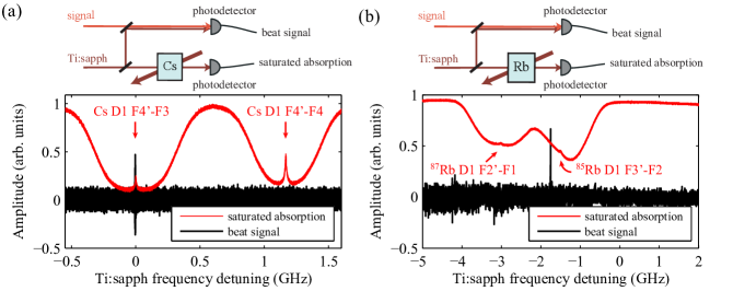
To generate PDC at the D1 lines of cesium and rubidium Schunk2015a , we first selected a nearly resonant PDC mode triplet by temperature (see Sec. II.3) and then tuned the signal frequency continuously (see Sec. II.4) to exactly the atomic resonance. The frequency of the generated signal can be measured at the MHz scale by beating it with a reference laser (SolsTiS cw Ti:sapphire laser from M Squared Lasers LTD). The frequency scan of the reference laser over the Doppler-broadened D1 lines of cesium in Fig. 11(a) and rubidium in Fig. 11(b) is used for an absolute frequency calibration. The cells containing the atomic vapors were long and kept at a temperature of . The employed method of sweeping the reference laser provides a large dynamic range of approximately for the measured frequency.

In Fig. 12(a) a zoom of the measured beat signal at the Cs D1 line (see Fig. 11(a)) is shown. The frequency sweep of the reference laser provides the time axis below and the frequency axis on top. The beat note is detected if it has frequency components below the bandwidth of the detector (). This requires that the frequency difference between the reference laser and the signal light central frequencies do not exceed the larger of their bandwidths. The reference laser has a bandwidth of . Hence, the frequency width of the beat note gives an upper bound for the bandwidth of the generated signal, which is well below one MHz. From theory, this bandwidth is determined by the pump laser bandwidth Debuisschert1993 ; Kozyreff2008 , which is approximately in the above threshold case. In contrast, the bandwidth of the signal mode is several MHz, which we investigate below threshold via signal-idler cross-correlation measurements (see Fig. 13).
The beat note shown in Fig. 12(a) is recorded for a longer period to demonstrate the frequency stability of our source. A short-time stability of about ( integration time) is achieved. This frequency stability is already below the natural linewidth of the Cs D1 line Steck2008all . The temperature of the WGMR is measured with a thermistor and stabilized with a proportional-integral-derivative controller with millikelvin precision. More advanced temperature locking techniques based on simultaneous measurements of two eigenmodes of the WGMR can allow for a temperature control with nanokelvin precision based on a simultaneous measurement of two orthogonal eigenmodes of the WGMR Strekalov2011 ; Weng2014 .
III.2 Atomic spectroscopy below the OPO threshold
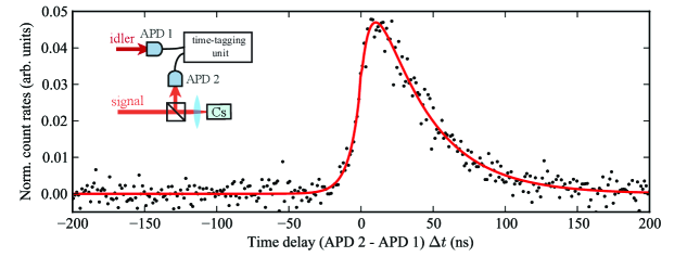
In this section we demonstrate one of the most basic applications of heralded photons matched in bandwidth and central wavelength to an atomic transition. Here we switch from linear photodetectors to Geiger-mode detection using avalanche photo diodes (APDs). For the idler photons we use ID220 from ID Quantique (APD 1) and for the signal photons SPCM CD 3017 from Perkin Elmer (APD 2). A stochastic absorption-emission of a heralded signal photon by an optical transition of an atom modifies its temporal correlation function with the heralding idler photon in a way that combines the optical transition and the resonator ring down times. This experiment was initially reported in Ref. Schunk2015a . We believe this experiment demonstrates an interesting approach to shape single-photon pulses for quantum optics applications (Maiwald2012, ; Bader2013, ) and for time-resolved single-photon spectroscopy of atomic transitions.
The signal-idler temporal correlation function is initially determined by the resonator ring down times and for the signal and idler modes, respectively. If these times are equal, , the correlation function takes the following form Ou1999 ; Michael2013 ; Luo2015 :
| (10) |
This function is normalized for unity probability:
| (11) |
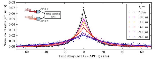
In WGMRs, the ring down time can be continuously tuned by changing the output coupling rate Michael2013 . In Fig. 13 we show several examples of the signal-idler correlation functions observed in our experimental setup under different coupling conditions. Each curve is normalized according to Eq. 11.
The signal-idler correlation function modified by a single absorption-emission cycle of the signal photon is shown in Fig. 14. To ensure that the scattering took place we collect photons in backward direction as shown in the inset of Fig. 14. To suppress multiple scattering events, the measurement was performed at low optical density when no radiation trapping occurred. Note that the opposite limit of high optical density may lead to the heralded single photon super-radiance Oliveira2015 .
The effect of a single absorption-emission cycle on the signal-idler correlation (Eq. 10) is adequately described in terms of a classical probability distribution. After re-emission, the signal has an additional delay with the following distribution function:
| (12) |
where is the atomic excited state life time. The probability density is also normalized:
| (13) |
The resonator and atomic decay events are statistically independent, so the composite distribution function of delay times and is given as a product:
| (14) |
Let us now introduce symmetric time variables and so that and . Note that is the time delay between the APD2 and APD1 firing, which is measured in the experiment.
We obtain
| (15) |
and
| (16) |
From we find the marginal probability distribution :
| (17) |
Computing the integral in Eq. 17 and substituting (dividing the probability density by preserves its normalization) in the result, we arrive at
| (18) |
Note that despite its segmented structure, remains analytic at .
We use Eq. 18 to fit of the correlation data in Fig. 14. The least-square fitting yields the resonator ring-down time ns (21.5 MHz bandwidth) and the atomic excited state decay time ns (4.3 MHz bandwidth) consistent with the natural linewidth of the Cs D1 line. We measured a Klyshko efficiency Klyshko1980 of for the idler photons and for the re-emitted signal photons from fluorescence. The Klyshko efficiencies in our experiment are currently limited by the ratio of coupling rate and bandwidth of the single photons, the fiber coupling efficiency, the relatively small collection angle (NA=0.4) for the photons from fluorescence, and the detection efficiency of the APDs.
IV Conclusion
In this work we have demonstrated the addressing of different atomic transitions with a narrowband photon pair source based on cavity-assisted parametric down-conversion. To achieve this, we characterized the central frequencies and bandwidths of the parametric light generated by our source, which is a triply-resonant whispering-gallery mode resonator made of lithium niobate. This source allows for stepwise tuning of the parametric frequencies over hundreds of nanometer by selecting specific mode triplets by temperature, and continuous tuning by amending temperature tuning with a second independent tuning mechanism. Resonators are manufactured from lithium niobate wafers by single point diamond turning and polishing techniques leading to quality factors of . A future implementation of this source in large-scale quantum repeater networks will require on-chip manufacturing, which currently reach quality factors of for lithium niobate Guarino2007 . Further studies may involve different resonator materials, different phase matching configurations such as cyclic phase matching Lin2013 , a coating of the WGMR to achieve a radially inhomogeneous refractive index Chowdhury1991 or advances in periodic poling of WGMRs Beckmann2011 ; Meisenheimer2015 , which is already a standard technique for linear crystals. Future studies may also improve the experimental control over the temporal and frequency profile by pulsed excitation to further optimize the applicability of WGMR based sources of quantum light.
Acknowledgments
The authors kindly acknowledge the support from Michael Förtsch, Navid Soltani, Ralf Keding, Andrea Cavanna, and Felix Just.
Funding information
The authors are grateful for the financial support of the European Research Council under the Advanced Grant PACART. Ch. M. acknowledges support from the Alexander von Humboldt Foundation.
References
- (1) H. P. Specht, C. Nölleke, A. Reiserer, M. Uphoff, E. Figueroa, S. Ritter and G. Rempe. A single-atom quantum memory. Nature 473, 190 (2011).
- (2) J. Hald, J. L. Sø rensen, C. Schori and E. S. Polzik. Spin Squeezed Atoms: A Macroscopic Entangled Ensemble Created by Light. Physical Review Letters 83, 1319 (1999).
- (3) K. Hammerer, E. Polzik and J. Cirac. Teleportation and spin squeezing utilizing multimode entanglement of light with atoms. Physical Review A 72, 052313 (2005).
- (4) M. Aspelmeyer, T. J. Kippenberg and F. Marquardt. Cavity optomechanics. Reviews of Modern Physics 86, 1391 (2014).
- (5) A. I. Lvovsky, B. C. Sanders and W. Tittel. Optical quantum memory. Nature Photonics 3, 706 (2009).
- (6) C. Simon, M. Afzelius, J. Appel, A. Boyer de la Giroday, S. J. Dewhurst, N. Gisin, C. Y. Hu, F. Jelezko, S. Kröll, J. H. Müller, J. Nunn, E. S. Polzik, J. G. Rarity, H. De Riedmatten, W. Rosenfeld, A. J. Shields, N. Sköld, R. M. Stevenson, R. Thew, I. A. Walmsley, M. C. Weber, H. Weinfurter, J. Wrachtrup and R. J. Young. Quantum memories. The European Physical Journal D 58, 1 (2010).
- (7) R. H. Dicke. Coherence in spontaneous radiation processes. Physical Review 93, 99 (1954).
- (8) A. Jechow, M. Seefeldt, H. Kurzke, A. Heuer and R. Menzel. Enhanced two-photon excited fluorescence from imaging agents using true thermal light. Nature Photonics 7, 973 (2013).
- (9) M. Fischer, M. Bader, R. Maiwald, A. Golla, M. Sondermann and G. Leuchs. Efficient saturation of an ion in free space. Applied Physics B 117, 797 (2014).
- (10) A. Ourjoumtsev, A. Kubanek, M. Koch, C. Sames, P. W. H. Pinkse, G. Rempe and K. Murr. Observation of squeezed light from one atom excited with two photons. Nature 474, 623 (2011).
- (11) T. Legero, T. Wilk, M. Hennrich, G. Rempe and A. Kuhn. Quantum Beat of Two Single Photons. Physical Review Letters 93, 070503 (2004).
- (12) J. Volz, M. Weber, D. Schlenk, W. Rosenfeld, J. Vrana, K. Saucke, C. Kurtsiefer and H. Weinfurter. Observation of Entanglement of a Single Photon with a Trapped Atom. Physical Review Letters 96, 030404 (2006).
- (13) J. Beugnon, M. P. a. Jones, J. Dingjan, B. Darquié, G. Messin, A. Browaeys and P. Grangier. Quantum interference between two single photons emitted by independently trapped atoms. Nature 440, 779 (2006).
- (14) P. Maunz, D. L. Moehring, S. Olmschenk, K. C. Younge, D. N. Matsukevich and C. Monroe. Quantum interference of photon pairs from two remote trapped atomic ions. Nature Physics 3, 538 (2007).
- (15) R. Maiwald, A. Golla, M. Fischer, M. Bader, S. Heugel, B. Chalopin, M. Sondermann and G. Leuchs. Collecting more than half the fluorescence photons from a single ion. Physical Review A 86, 043431 (2012).
- (16) P. Siyushev, G. Stein, J. Wrachtrup and I. Gerhardt. Molecular photons interfaced with alkali atoms. Nature 509, 66 (2014).
- (17) T. Utikal, E. Eichhammer, L. Petersen, A. Renn, S. Götzinger and V. Sandoghdar. Spectroscopic detection and state preparation of a single praseodymium ion in a crystal. Nature Communications 5, 3627 (2014).
- (18) N. Akopian, L. Wang, A. Rastelli, O. G. Schmidt and V. Zwiller. Hybrid semiconductor-atomic interface: slowing down single photons from a quantum dot. Nature Photonics 5, 230 (2011).
- (19) V. Leong, S. Kosen, B. Srivathsan, G. K. Gulati, A. Cerè and C. Kurtsiefer. Hong-Ou-Mandel interference between triggered and heralded single photons from separate atomic systems. Physical Review A 91, 063829 (2015).
- (20) X. H. Bao, Y. Qian, J. Yang, H. Zhang, Z. B. Chen, T. Yang and J. W. Pan. Generation of narrow-band polarization-entangled photon pairs for atomic quantum memories. Physical Review Letters 101, 99 (2008).
- (21) F. Wolfgramm, Y. A. de Icaza Astiz, F. A. Beduini, A. Cerè and M. W. Mitchell. Atom-Resonant Heralded Single Photons by Interaction-Free Measurement. Physical Review Letters 106, 053602 (2011).
- (22) J. Fekete, D. Rieländer, M. Cristiani and H. de Riedmatten. Ultranarrow-Band Photon-Pair Source Compatible with Solid State Quantum Memories and Telecommunication Networks. Physical Review Letters 110, 220502 (2013).
- (23) A. Lenhard, M. Bock, S. Kucera, J. Brito, P. Eich, P. Müller, C. Becher and J. Eschner. Telecom-heralded single photon absorption by a single atom. arXiv preprint arXiv:1504.08303 (2015).
- (24) B. Brecht, K.-H. Luo, H. Herrmann and C. Silberhorn. A versatile design for resonant guided-wave parametric down-conversion sources for quantum repeaters. arXiv preprint arXiv:1507.08840 (2015).
- (25) G. Schunk, U. Vogl, D. V. Strekalov, M. Förtsch, F. Sedlmeir, H. G. L. Schwefel, M. Göbelt, S. Christiansen, G. Leuchs and C. Marquardt. Interfacing transitions of different alkali atoms and telecom bands using one narrowband photon pair source. Optica 2, 773 (2015).
- (26) M. H. Dunn. Parametric Generation of Tunable Light from Continuous-Wave to Femtosecond Pulses. Science 286, 1513 (1999).
- (27) A. Savchenkov, A. Matsko, D. Strekalov, M. Mohageg, V. Ilchenko and L. Maleki. Low Threshold Optical Oscillations in a Whispering Gallery Mode CaF2 Resonator. Physical Review Letters 93, 243905 (2004).
- (28) P. Del’Haye, A. Schliesser, O. Arcizet, T. Wilken, R. Holzwarth and T. J. Kippenberg. Optical frequency comb generation from a monolithic microresonator. Nature 450, 1214 (2007).
- (29) J. Fürst, D. V. Strekalov, D. Elser, M. Lassen, U. L. Andersen, C. Marquardt and G. Leuchs. Naturally Phase-Matched Second-Harmonic Generation in a Whispering-Gallery-Mode Resonator. Physical Review Letters 104, 153901 (2010).
- (30) J. U. Fürst, D. V. Strekalov, D. Elser, A. Aiello, U. L. Andersen, C. Marquardt and G. Leuchs. Low-Threshold Optical Parametric Oscillations in a Whispering Gallery Mode Resonator. Physical Review Letters 105, 263904 (2010).
- (31) G. Lin, J. U. Fürst, D. V. Strekalov and N. Yu. Wide-range cyclic phase matching and second harmonic generation in whispering gallery resonators. Applied Physics Letters 103, 181107 (2013).
- (32) M. L. Gorodetsky and V. S. Ilchenko. Optical microsphere resonators: optimal coupling to high-Q whispering-gallery modes. Journal of the Optical Society of America B 16, 147 (1999).
- (33) M. Leidinger, S. Fieberg, N. Waasem, F. Kühnemann, K. Buse and I. Breunig. Comparative study on three highly sensitive absorption measurement techniques characterizing lithium niobate over its entire transparent spectral range. Optics Express 23, 21690 (2015).
- (34) J. Fürst, D. Strekalov, D. Elser, A. Aiello, U. Andersen, C. Marquardt and G. Leuchs. Quantum Light from a Whispering-Gallery-Mode Disk Resonator. Physical Review Letters 106, 113901 (2011).
- (35) M. Förtsch, J. U. Fürst, C. Wittmann, D. Strekalov, A. Aiello, M. V. Chekhova, C. Silberhorn, G. Leuchs and C. Marquardt. A versatile source of single photons for quantum information processing. Nature Communications 4, 1818 (2013).
- (36) A. N. Oraevsky. Whispering-gallery waves. Quantum Electronics 377 (2002).
- (37) M. Gorodetsky and A. Fomin. Geometrical theory of whispering-gallery modes. IEEE Journal of Selected Topics in Quantum Electronics 12, 33 (2006).
- (38) G. Kozyreff, J. L. Dominguez Juarez and J. Martorell. Whispering-gallery-mode phase matching for surface second-order nonlinear optical processes in spherical microresonators. Physical Review A 77, 043817 (2008).
- (39) T. Debuisschert, A. Sizmann, E. Giacobino and C. Fabre. Type-II continuous-wave optical parametric oscillators oscillation and frequency-tuning characteristics. Journal of the Optical Society of America B 10, 1668 (1993).
- (40) C. Richy, C. Schwob, K. Petsas, E. Giacobino and C. Fabre. Observation of bistability and delayed bifurcation in a triply resonant optical parametic oscillator. Proceedings of 5th European Quantum Electronics Conference 12, 456 (1994).
- (41) I. Breunig, B. Sturman, A. Bückle, C. S. Werner and K. Buse. Structure of pump resonances during optical parametric oscillation in whispering gallery resonators. Optics Letters 38, 3316 (2013).
- (42) Z. Y. Ou and Y. J. Lu. Cavity Enhanced Spontaneous Parametric Down-Conversion for the Prolongation of Correlation Time between Conjugate Photons. Physical Review Letters 83, 2556 (1999).
- (43) A. Predojević and M. W. Mitchell. Engineering the Atom-Photon Interaction: Controlling Fundamental Processes with Photons, Atoms and Solids (Springer, 2015).
- (44) G. Schunk, J. U. Fürst, M. Förtsch, D. V. Strekalov, U. Vogl, F. Sedlmeir, H. G. L. Schwefel, G. Leuchs and C. Marquardt. Identifying modes of large whispering-gallery mode resonators from the spectrum and emission pattern. Optics Express 22, 30795 (2014).
- (45) R. S. Weis and T. K. Gaylord. Lithium niobate: Summary of physical properties and crystal structure. Applied Physics A Solids and Surfaces 37, 191 (1985).
- (46) U. Schlarb and K. Betzler. Influence of the defect structure on the refractive indices of undoped and Mg-doped lithium niobate. Physical Review B 50, 751 (1994).
- (47) M. Förtsch, G. Schunk, J. U. Fürst, D. Strekalov, T. Gerrits, M. J. Stevens, F. Sedlmeir, H. G. L. Schwefel, S. W. Nam, G. Leuchs and C. Marquardt. Highly efficient generation of single-mode photon pairs from a crystalline whispering-gallery-mode resonator source. Physical Review A 91, 023812 (2015).
- (48) D. A. Steck. Rubidium 85 D Line Data, Rubidium 87 D Line Data, Cesium D Line Data. Los Alamos National Laboratory Technical Report, availabe at http:// steck.us/alkalidata (2008).
- (49) A. Guarino, G. Poberaj, D. Rezzonico, R. Degl’Innocenti and P. Günter. Electro–optically tunable microring resonators in lithium niobate. Nature Photonics 1, 407 (2007).
- (50) V. Ilchenko, P. Volikov, V. Velichansky, F. Treussart, V. Lefèvre-Seguin, J.-M. Raimond and S. Haroche. Strain-tunable high-Q optical microsphere resonator. Optics Communications 145, 86 (1998).
- (51) H. P. Wagner, H. Schmitzer, J. Lutti, P. Borri and W. Langbein. Effects of uniaxial pressure on polar whispering gallery modes in microspheres. Journal of Applied Physics 113, 243101 (2013).
- (52) I. Teraoka and S. Arnold. Theory of resonance shifts in TE and TM whispering gallery modes by nonradial perturbations for sensing applications. Journal of the Optical Society of America B 23, 1381 (2006).
- (53) C. S. Werner, K. Buse and I. Breunig. Continuous-wave whispering-gallery optical parametric oscillator for high-resolution spectroscopy. Optics Letters 40, 772 (2015).
- (54) R. Gerson, J. F. Kirchhoff, L. E. Halliburton and D. a. Bryan. Photoconductivity parameters in lithium niobate. Journal of Applied Physics 60, 3553 (1986).
- (55) K. Peithmann, A. Wiebrock and K. Buse. Photorefractive properties of highly-doped lithium niobate crystals in the visible and near-infrared. Applied Physics B: Lasers and Optics 68, 777 (1999).
- (56) J. Villarroel, J. Carnicero, F. Luedtke, M. Carrascosa, A. García-Cabañes, J. M. Cabrera, A. Alcazar and B. Ramiro. Analysis of photorefractive optical damage in lithium niobate: application to planar waveguides. Optics Express 18, 20852 (2010).
- (57) M. Jazbinšek and M. Zgonik. Material tensor parameters of LiNbO3 relevant for electro- and elasto-optics. Applied Physics B: Lasers and Optics 74, 407 (2002).
- (58) F. Vollmer and S. Arnold. Whispering-gallery-mode biosensing: label-free detection down to single molecules. Nature Methods 5, 591 (2008).
- (59) F. Sedlmeir, R. Zeltner, G. Leuchs and H. G. L. Schwefel. High-Q MgF2 whispering gallery mode resonators for refractometric sensing in aqueous environment. Optics Express 22, 30934 (2014).
- (60) W. L. Bond. Measurement of the Refractive Indices of Several Crystals. Journal of Applied Physics 36, 1674 (1965).
- (61) D. V. Strekalov, R. J. Thompson, L. M. Baumgartel, I. S. Grudinin and N. Yu. Temperature measurement and stabilization in a birefringent whispering gallery mode resonator. Optics Express 19, 14495 (2011).
- (62) W. Weng, J. D. Anstie, T. M. Stace, G. Campbell, F. N. Baynes and A. N. Luiten. Nano-Kelvin Thermometry and Temperature Control: Beyond the Thermal Noise Limit. Physical Review Letters 112, 160801 (2014).
- (63) M. Bader, S. Heugel, a. L. Chekhov, M. Sondermann and G. Leuchs. Efficient coupling to an optical resonator by exploiting time-reversal symmetry. New Journal of Physics 15, 123008 (2013).
- (64) K.-H. Luo, H. Herrmann, S. Krapick, B. Brecht, R. Ricken, V. Quiring, H. Suche, W. Sohler and C. Silberhorn. Direct generation of genuine single-longitudinal-mode narrowband photon pairs (2015).
- (65) R. A. de Oliveira, M. S. Mendes, W. S. Martins, P. L. Saldanha, J. W. R. Tabosa and D. Felinto. Single-photon superradiance in cold atoms. Physical Review A 90, 023848 (2014).
- (66) D. N. Klyshko. Use of two-photon light for absolute calibration of photoelectric detectors. Soviet Journal of Quantum Electronics 10, 1112 (1980).
- (67) D. Chowdhury, S. Hill and P. Barber. Morphology-dependent resonances in radially inhomogeneous spheres. JOSA A 8, 1702 (1991).
- (68) T. Beckmann, H. Linnenbank, H. Steigerwald, B. Sturman, D. Haertle, K. Buse and I. Breunig. Highly Tunable Low-Threshold Optical Parametric Oscillation in Radially Poled Whispering Gallery Resonators. Physical Review Letters 106, 143903 (2011).
- (69) S.-K. Meisenheimer, J. U. Fürst, C. Werner, T. Beckmann, K. Buse and I. Breunig. Broadband infrared spectroscopy using optical parametric oscillation in a radially-poled whispering gallery resonator. Optics Express 23, 24042 (2015).