TitFig
Nonlinear switching and solitons in PT-symmetric photonic systems
Abstract
One of the challenges of the modern photonics is to develop all-optical devices enabling increased speed and energy efficiency for transmitting and processing information on an optical chip. It is believed that the recently suggested Parity-Time (PT) symmetric photonic systems with alternating regions of gain and loss can bring novel functionalities. In such systems, losses are as important as gain and, depending on the structural parameters, gain compensates losses. Generally, PT systems demonstrate nontrivial non-conservative wave interactions and phase transitions, which can be employed for signal filtering and switching, opening new prospects for active control of light. In this review, we discuss a broad range of problems involving nonlinear PT-symmetric photonic systems with an intensity-dependent refractive index. Nonlinearity in such PT symmetric systems provides a basis for many effects such as the formation of localized modes, nonlinearly-induced PT-symmetry breaking, and all-optical switching. Nonlinear PT-symmetric systems can serve as powerful building blocks for the development of novel photonic devices targeting an active light control.
keywords:
PT-symmetry; photonics; nonlinearity; solitons; amplification1 Introduction
The concept of Parity-Time (PT) symmetry first emerged in the studies of quantum operators and their spectra [1, 2, 3]. Whereas it is well known that Hermitian operators have real spectra, Carl Bender and collaborators posed a question whether there exist non-Hermitian Hamiltonians which still have real spectra. They found that this can happen for a broad class of Hamiltonians which are symmetric with respect to the so-called PT transformations, defined by the parity operator as , and time reversal operator , as , where is a wave function in quantum mechanics. When a simple one-dimensional system is described by the Schrödinger-type Hamiltonian with a complex potential ,
| (1) |
where and are both real, the system (1) is called PT-symmetric provided , i.e. and . Although initially the analysis was motivated by the development of rather abstract quantum theories [1, 2, 3], it soon emerged that the concept of PT symmetry is relevant to various physical systems.
In optics, the propagation of light can often be described theoretically as an evolution governed by an effective Hamiltonian (1) in the so-called paraxial approximation. In this case variation of the medium refractive index is described by the potential . Hermitian Hamiltonians correspond to the cases where the optical energy is conserved and is real. On the other hand, the presence of losses or gain in optical structures maps to non-conservative non-Hermitian operators (1) with a complex . However, if such an operator possesses PT-symmetry and has a real spectrum, then the amplitudes of optical modes would be preserved, corresponding to an effective compensation of the effects of loss and gain, which can be important for a range of practical applications. First theoretical proposals for optical PT systems were formulated a decade ago [4, 5], and it was shown that in waveguiding structures, operator performs to spatial reflection, whereas reverses the propagation direction. Accordingly, conventional optical PT-symmetric structures have symmetrically positions regions of loss and gain, corresponding to the same real but opposite imaginary parts of the optical refractive index. The PT symmetry definition can be generalized to include the gauge transformations enabling applications to practical structures without exact balance of gain and loss [6], and including the structures with pure loss [7].
The spectrum of PT operators is not always real, and is inherently connected to the symmetry of the eigenmodes. If an eigenmode profile is invariant with respect to the PT transformation, then it has real eigenvalue. However, the modes with PT-symmetry-broken profiles generally have complex eigenvalues. The PT-symmetry breaking transition and the associated change from real to complex eigenvalues can be generally observed when the amount of gain/loss is increased [7, 6]. Such a phase transition can in particular facilitate single-mode lasing [8, 9] and find various other applications (see the recent review paper [10] and references therein).
Even before the PT symmetry concept was introduced, it was suggested that optical systems with gain and loss can improve the operation of nonlinear all-optical switching devices, including the lowering of the switching power [11, 12]. The development of PT concept brought a new perspective and stimulated further active investigations of nonlinear effects in PT-symmetric systems. In addition to switching, the topic of nonlinear self-focusing and the formation of self-localized solitons received a strong attention. Optical solitons in the conservative systems or the systems with low losses originate from a balance of nonlinearity and dispersion and usually form families of localized solutions [13]. In nonlinear dissipative systems, localized modes appear due to an additional balance of gain and loss at some special values of parameters and the existence of families of localized modes is very rare [14, 15]. While the PT-symmetric systems can be viewed as a special class of dissipative systems, they are quite unique, combining many features of conservative and dissipative systems, being able to support families of localized and periodic modes.
In this paper, we review the studies of nonlinear phenomena in optical PT symmetric systems. We discuss both theoretical concepts and predictions, as well as a relatively small yet quickly growing number of experimental demonstrations. We start with the discussion of the simplest configuration of PT-symmetric systems in optics in the form of a pair of coupled waveguides, an optical coupler, in Sec. 2. Then, in Sec. 3 we extend the discussion to multiple coupled waveguides, or oligomers. Further in Sec. 4 we analyse the properties of solitons in couplers and extended periodic systems. In Sec. 5, scattering of waves incident on nonlinear PT structures is considered. In Sec. 6, we discuss effects in PT structures, where gain and loss are modulated along the propagation direction. Finally, in Sec. 7 we present conclusion and outlook.
2 PT-symmetric couplers
A pair of coupled waveguides with gain and loss represents the simplest configuration of PT-symmetric optical system. However, such a system can already showcase rich physics and phenomena associated with the interplay of nonlinearity and PT-symmetry. In the following, we first overview the properties of linear couplers, and then discuss the effect of nonlinearity on the optical modes and the phenomenon of nonlinearly-induced PT symmetry breaking, as well as some generalizations.
2.1 Linear properties
Directional couplers composed of waveguides with gain and loss regions can be used to realize PT-symmetric optical structures. In the pioneering papers [4, 5], different designs of optical structures were suggested, where optical beams would exhibit an effective PT-symmetric potential. In such structures, the real part of the optical refractive index should be symmetric, and the imaginary part - antisymmetric, i.e.
| (2) |
This means that the absolute amounts of gain and loss should be the same, and gain/loss regions should have mirror configurations with respect to the central symmetry point.
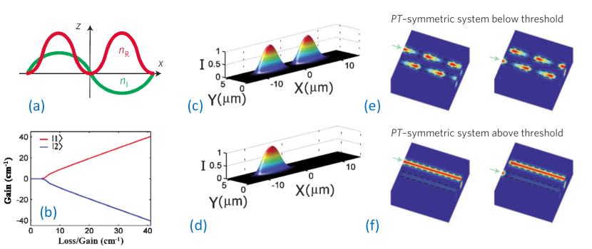
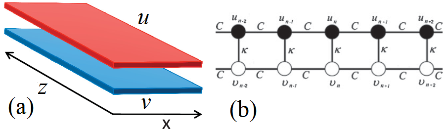
For experimental realization of optical PT couplers, directional couplers with different values of gain or loss in each of the waveguides were considered [7, 6], see Fig. 1(a). Beam propagation in such structures can be described by a pair of coupled equations for the amplitudes of modes in each of the waveguides, which can be represented in a Hamiltonian form as
| (3) |
where is the propagation distance, and are the mode amplitudes in the first and second waveguide, respectively, define the rates of gain in the first waveguide and loss in the second waveguide, and is the coupling coefficient between the modes of two waveguides.
The Hamiltonian possesses PT symmetry when applied together with Gauge transformation [7],
| (4) |
where parity operator swaps the mode amplitudes between the waveguides, , is a time-reversal operator which changes and performs a complex conjugation, is an identity matrix, and defines the average gain or loss between the two waveguides.
Important features of PT couplers become apparent by studying the properties of optical supermodes. These solutions have the form , where is the mode index. The mode propagation constants are , and the profiles are , where , , .
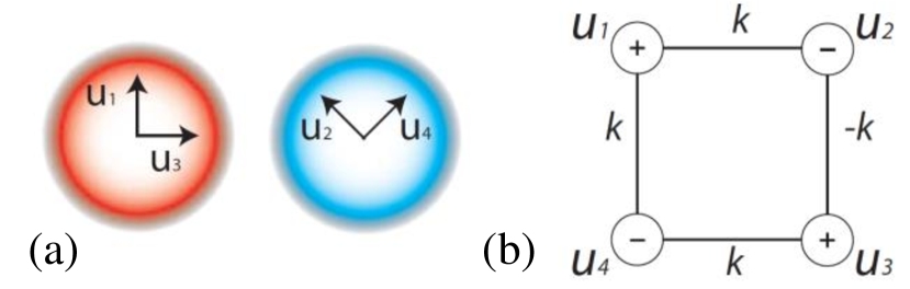
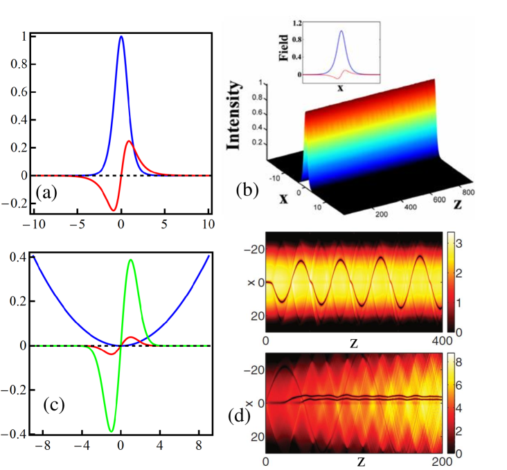
When , i.e. when the amount of gain and loss is below a critical value , then are real, accordingly , and both supermodes exhibit the same amount of gain/loss as , see Fig. 1(b). In this regime the supermode profiles are PT-symmetric, i.e. . Accordingly, the mode intensity is symmetrically distributed between the waveguides, i.e. , see Fig. 1(c).
However, when the gain/loss exceeds a critical value, , then become complex, supermodes exhibit different gain/loss [Fig. 1(b)], and their profiles become asymmetric and no longer conform to PT symmetry [Fig. 1(d)]. Accordingly, this regime is called broken PT-symmetry, referring to the symmetry of the supermodes.
An input optical beam in general excites a superposition of the supermodes, which properties thereby determine the beam dynamics. Below the threshold, the beating of two supermodes can lead to a periodic switching of light between the coupled waveguides, see Fig. 1(e). Such behavior is similar to a conventional conservative coupler, and indeed the power is conserved on average after every oscillation between the lossy and amplifying waveguides. The beating period is , and it grows monotonously as the gain/loss is increased, approaching infinity close to the critical threshold. Above the threshold, one supermode decays, and the remaining supermode primarily localized in the waveguide with gain determines amplification irrespective of the input condition, see Fig. 1(f).
2.2 Nonlinear coupler and symmetry breaking
The effect of nonlinearity on the beam dynamics in directional couplers composed of waveguides with gain and loss was originally described theoretically already two decades ago in Refs. [11, 12]. It was predicted that such structures can offer benefits for all-optical switching in the nonlinear regime, lowering the switching power and attaining sharper switching transition. In the last decade, the renewed interest in such structures as realizations of symmetric optical systems has led to a series of extensive theoretical and more recently experimental studies.
We first consider the effect of Kerr-type nonlinearity, which can modify the refractive index in each of the waveguides, depending on the optical intensity [11, 12, 16, 17, 18, 19]. This effect can be modeled by including nonlinear terms in the coupled-mode Eq. (3) as follows [17],
| (5) |
where the function characterizes the nonlinear response (we assume it to be real-valued), and is the loss/gain coefficient in the first and second waveguides. We will consider here the regime below the linear -symmetry breaking threshold, when .
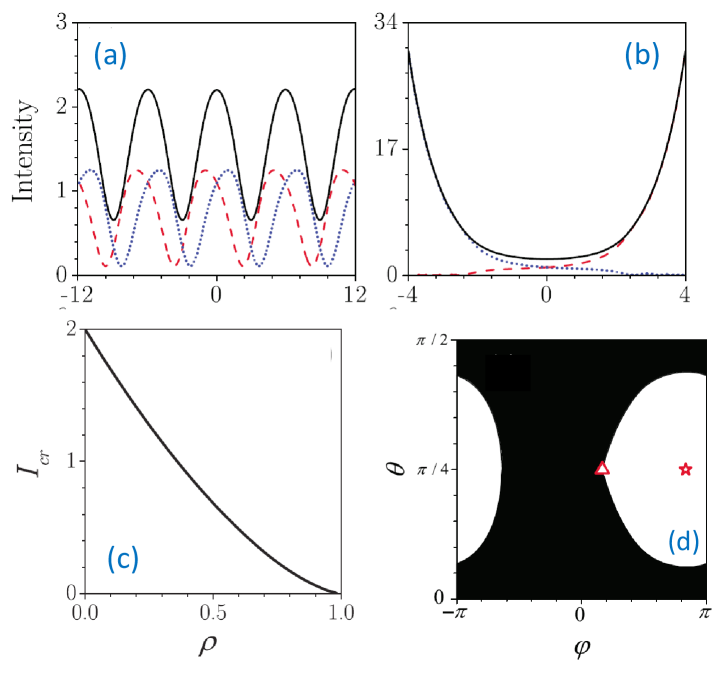
It was found that nonlinear solutions belong to two classes [17]: (i) periodic solutions, where the intensities and relative phases in two waveguides are exactly restored after each period () [Fig. 2(a)], or (ii) solutions where the total intensity grows without bound due to nonlinearly-induced symmetry breaking [Fig. 2(b)]. This classification is valid for arbitrary Kerr-type nonlinearities with smooth response functions . Quite remarkably, in case of cubic nonlinear response with , Eqs. (5) were shown to be integrable and their solutions can be formulated analytically [16, 18, 20, 21, 19, 22]. The dependence of the minimal input intensity () required for nonlinear switching on gain/loss coefficient is shown in Fig. 2(c), which illustrates that the threshold for nonlinear switching is drastically reduced for larger gain/loss coefficients.
It is convenient to represent the mode amplitudes in the following form,
| (6) |
where is the total intensity, and define the relative intensities and phases between the two input waveguides, and is the overall phase. Then, the initial conditions corresponding to different solution types (oscillating or growing) can be conveniently visualized on a phase plane, see an example in Fig. 2(d). This plot illustrates that even for high intensity above the threshold, the type of dynamics depends on the relative amplitudes and phases in the two waveguides. Interestingly, the type of nonlinear dynamics remains the same if we swap the intensities between the two waveguides, which corresponds to a transformation . In particular, we could couple light at the input just to the waveguide with loss, or to the waveguide with gain, and the type of dynamics would be the same. This is a counter-intuitive result, since in the first case the total intensity will initially decrease, whereas in the second case the total intensity will be growing. However, in both cases the type of dynamics will be determined only by the initial intensity level. This is a highly nontrivial consequence of linear PT-symmetry in the strongly nonlinear regime.
Whereas in general solutions are oscillating or growing, for particular initial conditions wave intensities can remain constant. Such regime corresponds to the excitation of stationary nonlinear modes, which can be viewed as a generalization of linear supermodes. They are positioned at the phase space points and , where , , and . The fixed point in phase space is a stable center if (i) and or (ii) and , where and (prime stands for the derivative). If these conditions are not satisfied, then the fixed point is a saddle, which indicates an instability. In case of self-focusing Kerr nonlinearity, with , the stationary point at is always stable at arbitrarily high intensities, whereas at the instability appears for . The stable point at is indicated in Fig. 2(d) by a star, and unstable at – by a triangle. We note that the unstable point is located at a boundary between the domains of periodic or growing solutions.
Nonlinear PT couplers can have applications for efficient all-optical signal manipulation with reduced switching power and the possibility to perform intensity-dependent amplification. Additionally, such couplers can operate as unidirectional optical valves [16] when nonlinearity breaks PT symmetry, as in this case the output beam becomes localized in the gain channel, irrespective of initial conditions. It was suggested that switching performance can be enhanced with application of Bragg gratings, involving specially engineered modulation of the real and imaginary part of the optical refractive index [23]. These concepts can be extended to other physical systems beyond optics, including electrical circuits [24, 25].
A PT-symmetric coupler, with additional gain and loss proportional to nonlinear terms has been studied in Refs. [26, 27, 28]. The system can be described by the following equations,
| (7) | |||||
| (8) |
where determines the nonlinearity strength and accounts for the PT-symmetric nonlinear loss and gain. The symmetric and asymmetric eigenstates of the system are found analytically. The additional nonlinear gain and loss result in the emergence of asymmetric solutions which not only are involved in symmetry-breaking bifurcations, but also produce asymmetric linearization matrices with spectral properties that reflect this asymmetry. If such nonlinear PT-symmetric coupler implemented into a linear chain, it may give raise to new types of nonlinear Fano resonances, with entirely suppressed or greatly amplified transmission [27].
2.3 Actively coupled waveguides
Nonlinearity can provide an important mechanism to balance gain and loss on average [29, 30, 22]. Such situation can arise even when linear PT symmetry is absent, in particular when the coupling between the waveguides is non-conservative and provides gain or loss depending on the relative phase between the guided modes [29]. Physically, this can be realized when a pair of nonlinear optical waveguides with absorption are placed in a medium with power gain. The evolution of mode amplitudes in two waveguides is governed by the following normalized equations,
| (9) |
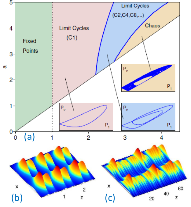
where is the net loss rate and is the active coupling coefficient. Note that these equations are different from Eqs. (5), and it was found that nonlinear dynamics demonstrates distinct regimes including stationary, periodic, and chaotic oscillations as outlined in Fig. 3(a).
The reason for the appearance of oscillations is the following. For , symmetric supermodes with exhibit a linear amplification rate . As the amplitude increased beyond a certain level, nonlinearity results in symmetry breaking and localization of light in one waveguides, and then the mode exhibits linear loss with rate approaching . Therefore, real nonlinearity acts as an effective nonlinear absorber. Examples of the resulting oscillations are shown in Figs. 3(b,c). An important advantage of the actively coupled nonlinear PT structure is its structural stability. For the given loss rate, the system supports stationary and periodic light beams in a wide range of gain coefficients. This is a fundamental distinction from the conventional PT-symmetric coupler discussed above, where one has to tune the gain to match the loss exactly to obtain periodic oscillations.
Another type of PT symmetry can appear when active coupling between the modes is nonlinear [31]. This can be potentially realized in a two waveguide coupler in the presence of a nonlocal nonlinearity, which respects PT symmetry. The corresponding model shows unique behavior, in particular admitting both bright and dark soliton solutions at the same time.
2.4 Anti-PT-Symmetry and parametric amplification
Nonlinear modes in PT potentials can also be supported by quadratic () optical nonlinearity [32, 33]. Compared to the case of Kerr-type nonlinearity discussed above, quadratic nonlinear response involves parametric coupling of the fundamental and second-harmonic optical waves. Such interactions give rise to a rich family of localized solitons.
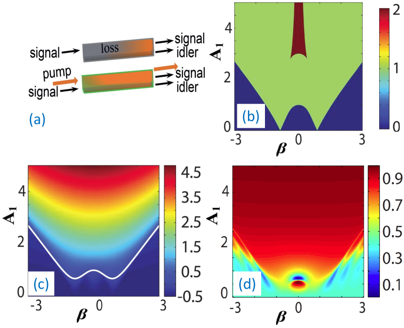
Quadratic nonlinearity can also facilitate a fundamentally important regime of parametric amplification, which is efficiently realized through difference-frequency generation [34]. Here the amplification rate is determined by the pump, enabling ultrafast all-optical tunability. Quadratic nonlinear PT-symmetric systems can, on one hand, realize ultrafast spatial signal switching through pump-controlled breaking of PT symmetry, and on the other hand enable spectrally-selective mode amplification [35]. The process of optical parametric amplification in PT coupler based on nonlinear mixing between a strong pump, and signal and idler waves is illustrated in Fig. 4(a). The evolution of near-degenerate (with close similar frequencies) signal and idler waves in the undepleted pump regime is modelled by coupled-mode equations, which can be represented in a Hamiltonian form:
| (10) |
where is a vector of wave amplitudes in the two waveguides, the subscripts stand for signal (‘s’) and idler (‘i’) waves in two waveguides (‘1’ and ‘2’),
| (11) |
defines the phase mismatch of parametric wave mixing, are the linear loss coefficients, is the mode coupling coefficient between the waveguides, and are the normalized input pump amplitudes.
Remarkably, the Hamiltonian possesses a spectral anti-PT symmetry, corresponding to a negative sign on the right-hand side of the following equality,
| (12) |
Here is a usual time-reversal operator which changes and performs a complex conjugation. The parity operators operate in spectral domain, interchanging the signal and idler waves,
| (13) |
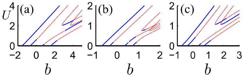
The Hamiltonian is linear, and the properties of its solutions are defined by the spectrum of its four eigenmodes. Overall, there can be three possible symmetry regimes: (i) two mode pairs with broken spectral anti-PT symmetry, (ii) one pair of PT-broken modes and a pair of anti-PT symmetric modes, or (iii) two pairs of anti-PT symmetric modes. Characteristic dependance of the number of PT-symmetric mode pairs in depending on the pump amplitude in the first waveguide and the phase-mismatch is shown in Fig. 4(b), and the largest mode gain is presented in Fig. 4(c). Remarkably, the established relations of mode symmetry and gain/loss are reversed in comparison to previously discussed spatial PT-symmetry in directional couplers, due to the spectral anti-PT symmetry of parametric wave mixing. Specifically, when all modes have broken spectral PT symmetry [blue shaded regions in Fig. 4(b)], the pairs of eigenmodes exhibit the same amount of gain/loss, and effectively the amounts of gain and loss are averaged out between the eigenmodes. However, upon transition to the region with spectrally PT-symmetric modes [green and red shaded regions in Fig. 4(b)], there appears an unequal redistribution of gain and loss between the modes. One PT-symmetric eigenmode exhibits gain much larger then all other modes, while the latter experience stronger loss. Such sensitivity of amplification to PT-breaking threshold could be used to discriminate between multiple spectral modes, analogous to the concept of PT-lasers [8, 9].
In case of perfect phase-matching, , and pump amplitudes of the same phase , the Hamiltonian also features spatial PT symmetry. Both the spatial and spectral PT-symmetry breaking occurs simultaneously at the threshold . However, the spatial and spectral symmetries are opposite: a mode pair is spatially PT-symmetric and has spectrally broken symmetry below threshold, whereas the situation is reversed above the threshold. Numerical simulations reveal a strong connection between spectral symmetry and spatial dynamics even for non-zero phase mismatches. Indeed, an increase of pump amplitude can control the period of mode coupling between the waveguides, while the oscillations get suppressed close to the spectral PT threshold, see Fig. 4(d). It is expected that due to the universality of parametric amplification processes, these concepts can be extended to different physical mechanisms including four wave mixing in media with Kerr-type optical nonlinearity.
2.5 Nonlinear modes
Analysis in previous sections was based on the consideration of coupling between the fundamental guided modes. However, new effects can appear when PT systems support multiple modes, including bound and extended (non-localized) states. Various types of double-well potentials have been investigated [36, 37, 38]. It was confirmed that discrete coupled equations can accurately describe the full continuous dynamics in a broad range of parameters. However, continuous models can be used to predict a range of important effects beyond two-mode approximation, such as the appearance of radiation losses in curved PT waveguides [36]. On the other hand, it was predicted that a PT structure placed in a nonlinear medium can trap soliton [39]. Furthermore, soliton scattering by a localized mode of PT coupler can exhibit nonreciprocal and non-conservative scattering, which is strongly dependent on the relative phase between the mode and the soliton [40].
Properties of nonlinear modes supported by a harmonic PT-symmetric potential also show a number of distinguishing features [41]. In particular, the modes bifurcating from different eigenstates of the underlying linear problem can belong to the same family of nonlinear modes. By adjusting the potential profile, it is possible to enhance the stability of small-amplitude and strongly nonlinear modes compared to the case of conservative real harmonic potential.
3 Discrete PT-symmetric oligomers
PT-symmetric discrete oligomers have recently attracted a lot of attention, motivated by possibilities of their experimental realisation [6, 16]. In particular, many scientific works address the questions of existence and stability of nonlinear states in PT-symmetric oligomers, which may drastically differ from eigenmodes of underlying linear systems. The nonlinear effects in PT-symmetric systems can be utilized for an efficient control of light including all-optical low-threshold switching and unidirectional invisibility [16, 42]. The possibility to engineer PT-symmetric oligomers, which may include nonlinearity, triggers a broad variety of studies on both the few-site systems and entire PT-symmetric lattices, including one-dimensional PT-symmetric dimer [43, 27], trimer [44, 43], quadrimer [43, 45], 2D PT-symmetric plaquettes [46, 45], and PT-symmetric finite/infinite chains [47, 48] and necklaces [49] and multicore fibers [50].
In this section we discuss PT-symmetric configurations consisting of three or more coupled waveguides. We first formulate the general model of finite discrete PT-symmetric oligomer and next consider some special configurations of PT-symmetric trimers and quadrimers. We also discuss finite open and periodic few-site geometries.
Consider an array of waveguides coupled to each other. We assume that each waveguide experiences some gain or loss determined by parameter , where is a waveguide number. Taking into account conservative Kerr nonlinear response, the light propagation through this system can be modeled by a system of discrete nonlinear Schrödinger equations (DNLSE),
| (14) |
where are mode amplitudes, , is the propagation distance, () corresponds to loss (gain), and are the coupling coefficients between sites and . We assume that is a real symmetric matrix, i.e. . The system (14) can be rewritten in matrix form as
Note that if H commutes with the operator, i.e. , then is a PT-symmetric matrix.
Stationary nonlinear modes of Eq. (3) are sought in the form , with propagation constant (eigenvalue) and w satisfying the following equation
| (18) |
Hereafter we assume that , which is a necessary condition for the system spectrum to be real [45].
In the following, we consider in detail two PT-symmetric geometries with the nearest-neighbor interaction and homogeneous coupling strength between the sites. Then the coupling coefficients can be expressed as .
3.1 PT-symmetric trimer
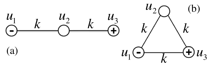
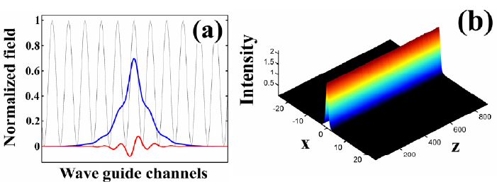
PT-symmetric trimer, first discussed in [43] and revisited in [51, 26] is schematically shown in Fig. 5. It is composed of three waveguides: active, lossy and conservative ones. In the linear regime there is only one possible PT-symmetric interposition of these waveguides with non-zero PT-symmetry breaking threshold: equal gain and loss parameters, i.e. , with conservative waveguide in the middle. The PT-symmetry breaking threshold is defined by the relation .
In the nonlinear regime, the dynamical equations for the open trimer [open boundary conditions, Fig. 5(a)] are
| (19) | |||
Here we are interested in the interplay of nonlinearity with PT-symmetry and its effect on stationary modes and their stability. We search for the stationary solutions of Eqs. (3.1) in the form , , and . Substituting these ansatz into Eqs. (3.1) we find relations on the soliton parameters,
Note that without loss of generality we may put , which yields , and thus
Thereby, all stationary modes of the PT-symmetric trimer possess equally distributed intensity between loss and gain waveguides.
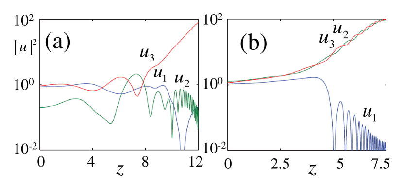
Analysis of Eqs. (3.1) shows that there are up to five (at least one) branches of stationary solutions of Eqs. (3.1) depending on the particular values of and . The dependence of these branches on gain/loss parameter for particular case has been discussed in detail in [43, 51]. Three different branches were found: first branch is mostly unstable (except small region that splits unstable region into two domains), while the second one is chiefly stable. These branches collide in a saddle-center bifurcation at and disappear. Interestingly, the third branch bifurcates from zero for and persists for larger values of even beyond the PT-symmetry breaking threshold , although this branch is unstable for . In Fig. 6 the system dynamics for the initial conditions belonging to the first branch is presented for two different values of gain/loss parameter . In Fig. 6(a) for (first unstable region), the nonlinear modes are unstable and the growth of intensity is observed in the active site , while two other modes and decay. In Fig. 6(b) for is taken from the second unstable region, but this time intensity growth is observed not only in the active waveguide but also in the conservative one. Both these types of dynamics are also observed for the second branch.
Note that in the considered case it is possible to find two additional branches of solutions of Eqs. (3.1) assuming to be complex-valued, although modes with such propagation constants will not be longer solutions of the original system (3.1). Such so-called ghost states can predict evolution of the systems (3.1) at short propagation distances [51].
The second configuration of the PT-symmetric trimer schematically depicted in Fig. 5(b) has also been investigated in Ref. [43] (and also discussed in [52]). Although the PT-symmetry breaking threshold for underlying linear system is , the nonlinear branches of solutions still exist for nonzero values of gain/loss parameter . Thus, nonlinearity provides stable stationary nontrivial solutions of the system, the linear spectrum of which has complex eigenvalues.
More complicated structure of PT-symmetric trimer including competing nonlinear gain with linear loss in the first waveguide and vise versa in the third waveguide has also been studied in [26]. The introduced nonlinear gain and loss give rise to rich features of asymmetric modes not observed in linear gain/loss profile systems.
It is worth to note here that experimental realization of dissipative trimer having ”gain-loss-gain” profile has been done in [51]. Although this trimer does not possess PT-symmetry, this experimental setup can be considered as a first step to realization of PT-symmetric trimer.
3.2 PT-symmetric quadrumer
In contrast to the PT-symmetric trimers considered above the four-site geometry admits several PT-symmetric configuration. Taking into account PT-symmetry requirements (symmetrical distribution of gain and loss sites) the general model of a one-dimensional PT-symmetric quadrimer with nearest-neighbor interaction [see Fig. 7] can be described by the following equations,
| (26) | |||||
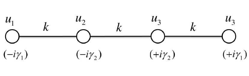
Similar to the trimer case, the existence and stability of stationary nonlinear modes for has been investigated in [43]. Such structure additionally possesses completely asymmetric solutions and the symmetry-breaking bifurcation structure is more complicated.
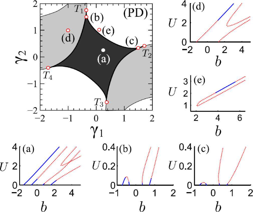
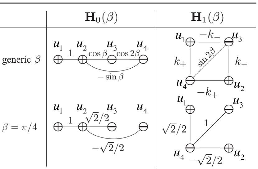
Let us consider in detail general case of bi-parameter gain and loss, i.e. [45]. The analysis of the underlying linear system of (3.2) shows that there are three types of regions in the parameter plane [see Fig 8 left top panel]: (i) unbroken PT-symmetry, with all eigenvalues real; (ii) broken PT symmetry with two real and two complex conjugated eigenvalues (this case is only possible for ); (iii) broken PT-symmetry with all eigenvalues complex. Note that there are ”triple” points in left top panel Fig. 8 denoted , which correspond to contact points of three regions. At these points, all eigenvalues , hereafter ”tilde” indicates eigenstates of the underlying linear system.
Next, we discuss an effect of nonlinearity on stationary modes, considering unbroken PT phase where eigenstates of the matrix of the system (3.2) are simultaneously the eigenstates of PT operator, i.e up to an irrelevant phase shift. Here is parity operator of the form
| (27) |
Hereafter are Pauli matrices and is zero matrix. It is reasonable to look for nonlinear modes possessing the same property . Thus, we may put and which leads to the set of equations
| (28) | |||||
| (29) |
Substituting and with real and into Eq. (28), we get , while from Eq. (29) we have . The roots of the equation immediately give us and . The latter equation can be reduced to the , where is a eighth-degree polynomial with real coefficients, each real root of which corresponds to a nonlinear branch of modes. Since the roots depend on continuously, we have continuous families of nonlinear modes for fixed system parameters. Note that these families of modes are additional to one found in [43] for the case . The branches of modes can be characterized by the total energy flow
| (30) |
In Fig. 8(a)-(e) the branches of solutions are depicted for the gain/loss parameters and corresponding to the points (a)-(e) in Fig. 8 left top panel. It is found that: (i) for small values of gain/loss parameters from the exact PT-symmetry phase region, nonlinear modes bifurcate from linear ones; (ii) if are chosen from an unbroken PT-symmetry region, but close to triple points as shown in Figs. 8 (b), (c), nonlinear modes bifurcate from linear limit, but rapidly loose stability and two of these branches cease to exist as reaches some critical value; (iii) the stable nonlinear modes can be found even in the region of broken PT symmetry [see Figs. 8 (d), (e)].
We now give a general perspective on the role of nonlinearity for PT-symmetric systems [45]. It is known that linear PT-symmetric systems exhibit similar behaviour (e.g. real spectrum and energy conservation of eigenmodes) as conservative ones, if they operate below critical point. Thus, there exists a unitary equivalence between PT-symmetric and Hermitian systems [53, 54]. In terms of considered oligomers (we return to matrix representation (3)), it means that there is a unitary matrix that transforms exactly PT-symmetric matrix (in PT unbroken phase) into Hermitian one with the same set of eigenvalues, i.e. . This new matrix will include coefficients , which will determine the coupling strength. Thus, the following question naturally arises: are there any significant differences between these PT-symmetric and Hermitian systems having the same eigenvalues in nonlinear regime?
To answer this question we introduce new system, described by the equation , where can be constructed explicitly, following [53, 54]. Families of stationary nonlinear modes of this new system were obtained in [45] and are presented in Fig. 9 for the same values of as in Figs. 7 (a)-(c). While for taken from the ”middle” of the unbroken PT phase the behaviour of mode branches for PT-symmetric and Hermitian systems looks similar (except their stability regions)[cf. Fig. 8(a) and Fig. 9(a)], for placed near the border of the unbroken PT phase, the difference becomes significant [cf. Figs. 8 (b),(c) and Figs. 9 (b),(c)]. While for the Hermitian system the mode branches do not change qualitatively depending on and there is always at least one stable branch, in the PT-symmetric case there is a bifurcation of two branches and loss of stability for even small values of the energy flow .
From the result above, there could be an impression that an existence of continuous families of the nonlinear modes is an attribute of PT-symmetric systems. To check this conjecture, we consider the case , but this time take into account not only the nearest-neighbor interactions, according to the following matrix:
| (35) |
where determines a coupling strength. This structure is schematically shown in Fig. 10 in the left top corner. This configuration is symmetric with respect to the operator
| (38) |
where . Note that coincides with the case considered above for .
It can be shown that admits continuous families of nonlinear modes only for discrete number of points [45]. Thus, continuous families of nonlinear modes do not always exist for PT-symmetric system.
Interestingly, by using appropriate transformation, e.g.
| (41) |
with , it is possible to obtain new PT-symmetric matrix with the same set of eigenvalues. Thus, the PT-symmetric quadrimer can be reconfigured to a PT-symmetric plaquette. In Fig. 10 the graph representations of both PT-symmetric quadrimer and PT-symmetric plaquette are shown for a generic case of arbitrary and a particular one with . Here .
The PT-symmetric plaquettes can also be considered as blocks for construction of two-dimensional PT-symmetric lattices. Therefore, it is important to figure out what are the properties of the nonlinear modes in such structures. Four types of fundamental PT-symmetric plaquettes corresponding to different interpositions of active and lossy waveguides were studied in Ref. [46] (one of possible realisation of such a plackets is presented in Fig. 11(b)). Existence of solution branches past the critical point of the underlying linear system and the appearance of additional asymmetric modes were reported, although most of the stationary modes were found to be unstable.
The plaquette models can describe real physical systems such as PT-symmetric multi-modes fibers [55, 56], including PT-symmetric coupler with birefringent arms was considered in [55]. The schematic of such a coupler and its graph representation are shown in Fig. 11. The coupling between elements includes both linear and nonlinear nature, which complicates the mode structure. Stationary modes with different polarisation were obtained and regions of their stability were identified.
3.3 Multicore fibers
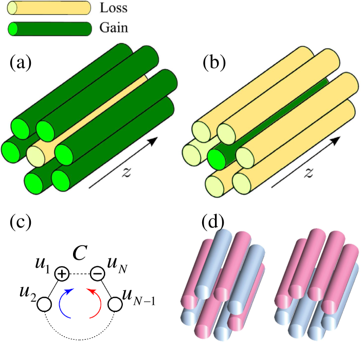
Being driven by rapid development of multicore optical fibres, the theory of coherent propagation and power transfer in low-dimensional array of coupled nonlinear waveguides has been suggested [57, 58]. This offers an opportunity to explore the multicore waveguide systems with PT-symmetry in the presence of gain and loss. Existence, stability, and dynamics of both linear and nonlinear stationary modes propagating in radially symmetric multicore waveguides with balanced gain and loss have recently been studied [50]. A multicore waveguide array of identical waveguides arranged in a circular geometry with the central one being gain (loss) and all peripheral ones being loss (gain), as shown in Fig. 12(a)-(b), has been investigated. Taking into account only nearest-neighbor interaction, the evolution equations for the mode amplitudes read as,
where , and denote the mode amplitude, refractive index, and gain/loss parameter in the central core waveguide, respectively, while , and are the same but in the -th waveguide on the ring. Here and and the nonlinear coefficients for all waveguides are identical and characterized by . is the coupling coefficient between the core and other waveguides on the ring, while stands for the coupling between two nearest-neighbors on the ring.
It has been demonstrated that the system can generally be reduced to an effective PT-symmetric dimer with asymmetric coupling. In the linear regime, , the bounded dynamics can be observed in the limit of the effective dimer and for the active core waveguide. Here two modes with real propagation constants exist before a critical value of gain and loss for an onset of PT-symmetry breaking, while other modes always have imaginary propagation constants. This directly relates to a stable (unstable) propagation of modes when gain is localized in the core (ring) of the waveguide structure.
In the case of self-focusing nonlinearity (), an interplay between nonlinearity, gain and loss results in a high degree of instability, and quasi-stable propagation may appear under some parameter conditions. By reducing to the effective dimer, several stationary modes were found, however these stationary modes turned out to be unstable in the presence of nonlinearity and nonzero gain and loss. More interestingly, when a spatially periodic modulation is applied, stabilization of nonlinear modes can be achieved.
Nonzero energy flow between gain and loss waveguides may affect such entities as discrete vortices in the ring geometry including PT-symmetric elements [see Fig. 12(c)] [52]. One of the important characteristics of the vortex modes is a topological charge which is equal to the phase winding number in units of around the vortex origin and the sign of determines the direction of power flow. It has been shown that degenerate linear vortex modes spontaneously break PT symmetry, however nonlinear propagation modes still can be found. By breaking T symmetry, the existence, stability and the dynamics of nonlinear vortex modes become sensitive to the sign of their charge , offering an additional degree of freedom for all-optical control of discrete vortices.
Generalization of the two-channel dispersive coupler [59] to a PT-symmetric arrangement of dispersive waveguides has been done in [49]. The arrays of waveguides in the form of periodic necklaces with alternating and clustered gain and loss distribution [see Fig. 12(d)] were discussed and asymptotic behaviour of the PT breaking threshold with number of sites was derived. Thus, for the alternating array , while for the clustered geometry as .
4 Solitons in couplers and periodic potentials
Since the discovery of solitary waves in shallow water by Scott Russell in 1834, solitons have attracted a lot of attention due to their importance in many nonlinear physical systems, ranging from solids to Bose-Einstein condensates [60]. In optics, solitons were investigated and described in many research papers and books (see, e.g., Ref. [13]). Conservative solitons requiring balance of nonlinear response and medium dispersion usually form families with different amplitudes. Nonlinear dissipative systems, however, demand an additional balance between gain and loss to support soliton solutions [15, 14]. This latter requirement is usually satisfied only for particular soliton amplitudes and shapes, thus no continuous families can generally be found. In their turn PT-symmetric systems belong to a subclass of dissipative systems, however due to the symmetry property they can commonly support families of solitons with different amplitudes [61]. Accordingly, PT symmetric systems are unique, combining certain features of conservative and dissipative systems.
In this section, we discuss how PT-symmetry affects the soliton properties compared to conservative or dissipative systems.
4.1 Solitons in PT-symmetric couplers
First, we consider a planar PT-symmetric coupler where light experiences diffraction in the direction and propagates along the coordinate [62, 63, 64, 59]. Figure 13 (a) show a schematic pretention of the coupler where the red plane stands for a waveguide with gain, while the blue plane shows a lossy waveguide.
This structure can be described by the normalized system of coupled-mode equations:
| (44) | |||
where and are the mode amplitudes in the waveguides with gain and loss, respectively, is the gain/loss coefficient. System (44) supports two types of soliton solutions: symmetric and antisymmetric [62, 63], termed by analogy with conservative systems (when ) [13]. These two solitons can be presented in the following form:
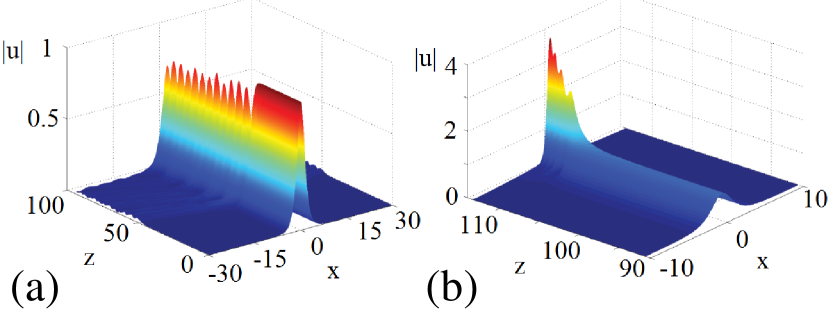
Here , , , are the soliton amplitude, velocity and propagation constant, respectively, satisfying the relation with and . The signs correspond to the symmetric and antisymmetric solitons, respectively. Stability analysis reveals that symmetric solitons are stable if , while antisymmetric solitons are always unstable. However, their lifetimes are exponentially long if amplitudes are small enough, so they could be considered to be stable in practice. Generally speaking, it is easy to show that under assumption Eqs. (4.1) can be reduced to a single conservative nonlinear Schrödinger equation. It means that, if the solitons (4.1) are stable, then their properties do not differ from ones of their conservative counterparts, and full energy of the system is exactly conserved. However, unstable behaviour of such solutions may demonstrate unique features. If the soliton amplitude exceeds the critical value, two types of unstable dynamics for each type of solitons are possible: the emergence of breathers with oscillating energy or unbounded growth of the mode intensity in the waveguide with gain. In the conservative case, the latter type of dynamics leads to formation of an asymmetric soliton, which concentrates mostly in one waveguide. Since the asymmetric solitons break a balance of gain and loss in PT systems, it leads to the PT-symmetry breaking. Examples of these unstable behaviors are presented in Fig. 14 for a symmetric soliton.
The considered system supports not only fundamental solitons, but also stable -soliton complexes as well [64]. It turns out that unlike the fundamental solitons considered above, the stability region for the antisymmetric two-soliton is considerably larger than for its symmetric counterpart.
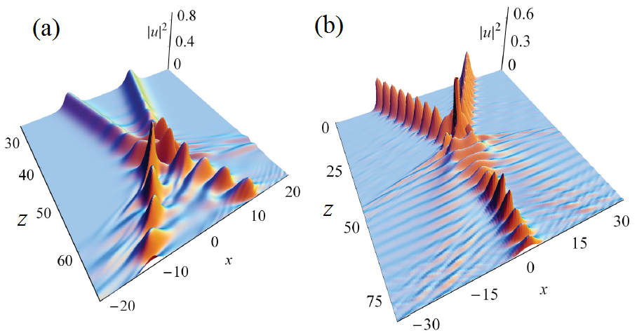
As mentioned above, unstable solitons can transform into breather-like objects [59]. Such nonlinear modes are stable on the distances of , where gives the scale of the amplitude of the small-amplitude breathers. The breathers are more common objects in the planar PT-symmetric coupler in the following sense. Propagation of low intensity light (determined by ) is governed by a conservative system of amplitude equations obtained in [59]. This system admits soliton solutions, which correspond to breather solutions in original model (44) as well as degenerate soliton solutions, which are symmetric and antisymmetric solitons of the model (44). Breathers can be produced resulting from collision of symmetric and antisymmetric solitons [see Fig. 15(a)] as well as at fission of unstable solitons[see Fig.14 (a)]. Remarkably, although the breather energy is not conserved during propagation, it is conserved on average. An interesting example of breather dynamics with merging of two breathers into one is shown in Fig. 15(b). Breathers dynamics is very sensitive to a relative phase of interacting breathers [66]. Thus, for fixed initial conditions varying only a relative phase of the colliding breathers the different types of dynamics such as merging two breather into one (temporal or permanent), elastic collision, collision with energy exchange and PT-symmetry breaking are observed.
A nonlinear dissipative coupler can demonstrate unique features due to PT-symmetric behaviour. ”Zeno”-like effect was observed in numerical simulation [67] for a system obtained from Eq. (44) by replacing the waveguide with gain by conservative one. The Zeno phenomenon, introduced in quantum mechanics [68] and consisting in strong suppression of the decay of an unstable particle by means of frequent measurements. In terms of considered model more frequent measures correspond to stronger loss in the system.
Generally speaking, the new system is no longer PT-symmetric, however, a linear analogue of such a system can be brought to PT-symmetric view by simple change of variables [7]. As discussed above, if the gain/loss parameter is below the PT-symmetry breaking threshold there appears beating of light between the waveguides, while in the opposite case this beating is suppressed, and light gets localized in the waveguide with gain. At the same time, the systems with loss only also exhibit similar dynamics. Thus, stronger loss in the system suppresses beating of light, locking it in the conservative waveguide and making the whole system more transparent (see Fig. 16).
A discrete analogue of the model (44) has been considered in Ref. [65]. The structure is a chain of linearly coupled PT-symmetric dimers shown schematically in Fig. 13(b). An important distinction of the discrete model from its continuous counterpart is that the former model possesses discrete linear spectrum providing additional possibility for solitons to be stable. Two types of solitons, symmetric and antisymmetric, were constructed numerically, and their properties were investigated. It turns out that the discrete PT-symmetric lattice supports freely moving solitons. Solitons behave quite similar to solitons in conservative systems provided they are stable and their amplitude does not exceed a critical value determined as . If soliton amplitude exceeds , the component of the soliton, which experiences gain, grows exponentially, while the component with loss, , quickly decays.
The discussed model (44) as well its discrete counterpart do not admit dark soliton solutions [see for example [65]]. However nonlinear coupling between waveguides (cross-phase modulation) can facilitate the formation of dark and bright solitons. Also stable rogue waves of the Peregrine type were identified [69, 70]. It was shown that gain/loss parameter modifies the region of stability of both background of dark solitons as well as solitons themselves.
4.2 Solitons in localized potentials
As was mentioned above, the necessary condition for one-dimensional optical system to be PT symmetric is [71]. The presence of nonlinear response of a medium, generally speaking, changes the real part of system potential making eigenvalues of the Hamiltonian complex-valued. However, judicious distribution of an intensity in such systems may retain eigenspectrum to be real.
Light propagation through the waveguide with a modulated refractive index in transverse direction () and experiencing gain and loss is described by the normalized equation
where satisfies the condition above for PT-symmetric systems. In this section we consider the case, when both and are localized in transverse direction .
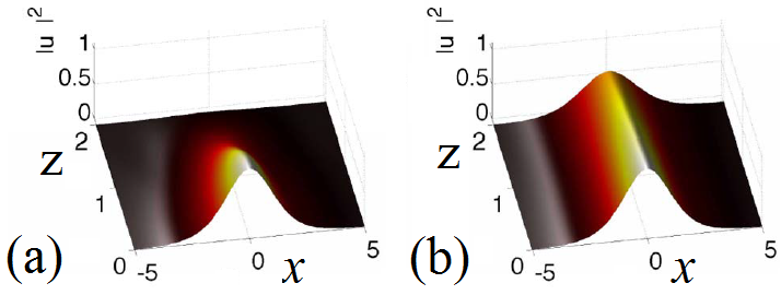
Stable solitons in PT-symmetric systems with distributed gain and loss were first reported in Ref. [71]. Particularly, the potential of Scarff form , has been considered for focusing type of nonlinearity [see Fig. 17 (a,b)]. It has been revealed that the system possesses real linear spectrum if . However, even if this condition is broken (linear spectrum is complex), nonlinear modes can alter the amplitude of refractive index due to nonlinearity, thus bringing the system into PT-symmetric phase. Some analytical solutions have been obtained in [72] for 1D and 2D PT-symmetric wells and lattices.
Although the soliton in Fig. 17(b) looks similar to ones determined by Eq. (4.1) and depicted in Fig. 14, in fact they are completely different. Each of the components, and , of the soliton (4.1) experiences pure gain or loss respectively, and the energy flow is directed from the gain waveguide to the lossy one. The soliton presented in Fig. 17 has only one component, which is partially situated in both gain and loss regions. This soliton has the transverse energy flow, which strongly affects its properties, e.g. stability and mobility.
In the case of defocusing nonlinearity [74, 75, 76], gray solitons, nonlinear guided modes as well as bright solitons in nonlocal nonlinear media, have been found to be stable in PT-symmetric localized potential of the Scarff type.
In Ref. [77] stable fundamental soliton, as well as two- and three-soliton solutions, have been reported for the Gaussian PT-symmetric potential of the form .
An interesting study of the behaviour of dark solitons near the phase transition points was reported in Ref. [73]. A parabolic trap potential of the form and was considered [see Fig. 17(c)] and it has been found that dark solitons are stable if the amplitude of the imaginary potential, , is less than . An unstable soliton of an oscillating type is shown in Fig. 17(d)(top panel) for and . Above this critical value, the dark-soliton background demonstrates exponential growth corresponding to the blow-up due to PT-symmetry breaking. However, if exceeds some critical value, namely in the considered case, then instead of the exponential growth one observes the soliton generation from a background state [see Fig. 17(d), bottom panel]. This critical point corresponds to blue-sky bifurcation of the background state and the fundamental soliton branch, after which they cease to exist. The same type of bifurcation is also observed for soliton branches of higher orders, which are found for larger values of , i.e. 2-soliton branch bifurcates with 3-soliton branch at some etc. Thus, for larger values of (strong gain/loss) we may observe spontaneous generation of multiple dark solitons from an input beam.
4.3 Solitons in periodic potentials
Next, we consider soliton solutions in structures having periodic modulation of both a real part of the refractive index as well as gain/loss regions. The governing equation for light propagation has the form of Eq. (4.2), but potential is periodic.
Linear properties of such a system have been investigated in Ref. [78]. It has been shown that nonorthogonality of thed Floquet-Bloch modes for PT-symmetric potentials leads to effects such as double refraction, power oscillation (due to unfolding of nonorthogonalized Floquet-Bloch modes), nonreciprocity, and secondary emission in 2D case. These linear attributes of PT-symmetric system may also be observed in nonlinear models and are fundamental phenomenons that distinguish PT-symmetric systems from conservative ones.
In the case of self-focusing nonlinearity, , soliton solutions have been investigated for the potential of the form , [71]. It is interesting that nonlinear response in such systems can shift PT-symmetry breaking threshold enabling one to find nonlinear mode with real propagation constant even though the associated linear spectrum is complex. It turns out that the solitons can be stable over a wide range of model parameters. Furthermore, narrower self-trapped waves are more stable and it is possible to find stationary modes even above PT-breaking threshold, but this class of solitons unfortunately is unstable. Potential distribution as well as stable soliton propagation are shown in Fig. 18.
A system of superlattices with and has been studied in [79]. Parameter here controls the relative strength of the superlattices. Stable solitons propagating in the low power region were found in semi-infinite gap. The relative strength of the superlattices may significantly vary PT breaking threshold as well as region of soliton stability.
For the defocusing nonlinearity, , multi-peak gap solitons exist and are stable over a wide range of parameters in a first gap of the potential of the form [80]. It is remarkable that stable solitons with larger number of peaks exist for a wider range of propagation constant.
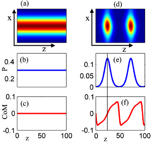
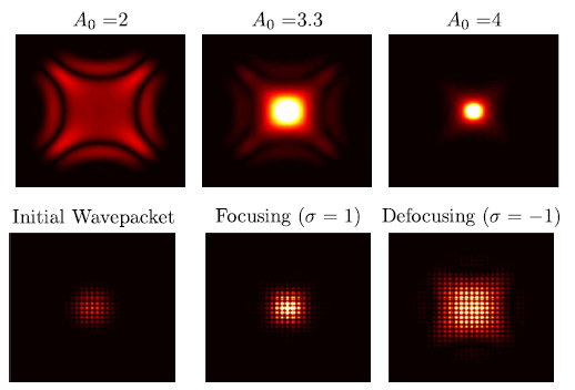
Interesting finding has been obtained in Ref. [81]. It turns out that nonlinearity may cause a transition from broken to PT symmetric phase for focusing nonlinearity and vice versa for defocusing one. Nonlinear band structure has been obtained for different strength of nonlinearity and it has been revealed, that the greater the nonlinearity strength, the smaller region in the Brilliouin zone where the eigenenergies are complex. When power reaches a certain threshold, the whole spectrum becomes real. Thus, two different dynamical regimes for nonlinear wave packet near the phase transition point were observed. First, if an initial power of a propagating packet is large enough for a transition of the system to PT-symmetric phase, then intensity and power are invariant throughout propagation. In Figs. 19 (a-c) an intensity, power and center of mass of the propagating packet are presented for this case. Second, if the initial power of the packet is too low to induce transition, then the intensity and power start to grow [see Fig. 19 (d-f)]. After power passes the level at which spectrum becomes real it continues to grow until it reaches some maximum value (indicated by black line in Figs. 19 (e,f)) and after that it starts to decay bringing the system to the original state. This dynamics can be explained as follows: the evolution starts an the center of unit cell (we consider here only one period of the potential. Since the initial power is low (linear regime) we can decompose the packet into two eigenmodes, one of which is growing and the second one is decaying. The growing eigenmode resides mostly in the gain half of the unit cell, while decaying - in the loss half. After the decaying mode dies out, the center of mass of the packet is shifted along the potential minima to the gain region. Then it starts to move in opposite direction along with the power growth and ends up in the loss region. The power of the packet starts to decay, bringing the system to PT broken phase and the process repeats again. Both of these dynamical regimes are stable and numerical simulations indicate that such propagation should continue indefinitely. The second type of dynamics is associated with any continuous physical systems and is not observed in systems modeled by a standard tight-binding model, since for nonlinearity induced transition the space overlap of modes corresponding to gain and loss should be presented. This effect allows to design systems that can switch from being power conservative to amplification regime.
Behaviour of wavepackets near the phase transition point has been studied in [82]. In this case the envelope dynamics of the propagating packets can be described by nonlinear Klein-Gordon equation (Eq. (13) in [82]). Based on this envelope equation a variety of phenomena such as wave blow up, periodic bound states and solitary waves are predicted and corroborated by comparison with numeric simulation of full model (4.2).
A discrete counterpart of the PT-symmetric periodic potential can be realized by appropriate alteration of coupled waveguides with gain and loss. Such discrete structures are easier to fabrication then the waveguides with continuously varying refractive index as well as gain/loss strength. Solitons in discrete PT-symmetric lattices have been investigated in a series of works [83, 84, 18]. A chain of alternating PT-symmetric couplers was considered in [83]. The field evolution along the waveguides is described by the system
| (47) |
Here and are the mode amplitudes in waveguides with loss and gain, respectively, and - coupling coefficients. In the linear regime the system has real eigenspectrum if . It has been shown numerically that this lattice supports stable soliton solutions. These solitons might be actively reshaped or switched to PT-broken phase by a small-amplitude modulation of the gain/loss parameter along the propagation direction . Later, in the work [84] an analytical proof of existence of such solitons was given and classification of solution families and their stability was provided. Moreover, by analytical continuation from the anticontinuum limit it is possible to show that localized discrete solitons exist in a network of PT-symmetric clusters (oligomers).
4.4 Generalized nonlinear potentials
In this section we consider PT-symmetric systems with generalized nonlinear response such as nonlocal nonlinearity, cubic-quintic competing nonlinearity, and mixed linear-nonlinear PT-symmetric potentials etc. The field evolution in one-dimensional systems with a general type of nonlinearity can be described by the following normalized equation
| (48) |
where is a functional determining the nature of nonlinear response.
Nonlocal nonlinear response appears in such systems as photorefractive crystals, nematic liquid crystals, lead glasses, etc. This nonlinear response can significantly modify the soliton properties such as existence, stability, and mobility. The function satisfies the following equation . Here is a degree of nonlocality of the nonlinear response. Several papers were devoted to the study of gap solitons and defect modes in self-focusing nonlocal nonlinear media. In Ref. [85], the existence and stability of defect modes were studied for different values of the nonlocality parameter , as well as for different types of defects. In Ref. [86], gap solitons were studied in dual periodic lattices, while Ref. [87] was devoted to the study of defect modes in PT-symmetric superlattices. In Ref. [88] the effect of spatially modulated nonlocal nonlinearity has been addressed. It was shown that there exist regions where gap solitons and defect modes are stable, and that the degree of nonlocality affects this region drastically.
Defocusing type of nonlinearity has been considered in [89]. The existence and stability of gap solitons in media with diffusive-like nonlinear response were determined. The gap solitons are always oscillatory unstable for any degree of nonlocality in the presence of an imaginary potential.
It has also been shown that PT-symmetric periodic lattices can support a variety of stable vector solitons consisting of multiple bright beams in both focusing and defocusing media [90]. Dynamics of such solitons is described by Eq. (4.2) where is a two component vector. In the component form Eq. (4.2) becomes a system of two incoherently coupled-mode equations. Stable solitons can be found even if both components have different propagation constants, but to satisfy the PT-symmetry condition these solitons must have equal number of humps in each component. It also may happen, that one of the component is unstable itself, while the other is stable. In this case the soliton can be stable due to the coupling of these two components. Analysis of an effect of gain/loss strength on soliton stability revealed that stronger gain/loss coefficient can destabilize soliton in focusing media and stabilize it in defocusing one.
The case of spatial periodic modulation with Kerr-type nonlinearity also including gain/loss modulation has been considered in Ref. [91]. In this case with zero linear potential and the functions and have the same modulation period. Analysis of the soliton existence and stability reveals that in the case of zero real part of the nonlinear potential there exists a non-vanishing region of parameters where stable solitons exist. The modes with the width less then a half of the lattice spacing appear to be stable. The system supports stable multihump solitons. Stable solitons were found in the lattice with mixed linear-nonlinear PT-symmetric optical potentials [92]. Some exact solutions to the system with mixed linear-nonlinear PT-symmetric potentials were obtained in Ref. [93].
An effect of multistability has been observed in a model with competing cubic-quintic nonlinear response with [94, 95]. At this type of nonlinear response for low intensities of light the focusing nonlinearity prevails on defocusing one, while for high intensities defocusing dominates. It has been shown [95] that solitons with different symmetries and different number of humps can propagate with the same propagation constant. Another interesting point is that both even and odd hump solitons can be stable over some range of propagational constants, which is in contrast to conservative case, where only lowest branches of solitons of both types can be stable. Thus imaginary part of the potential can stabilize solitons in the first gap.
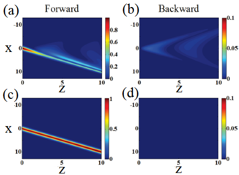
In the work [96] the effect of PT-symmetric potential on Bragg solitons has been studied. These solitons are composed of interlocked both forward and backward propagation modes. Such interlocking open up forbidden band gap allowing energy transport. It is interesting that at the exact PT phase transition point the exchange of energy between forward and backward modes ceases, and full energy is conserved. Below PT breaking threshold, there is oscillatory power exchange between forward and backward modes [see Fig. 20].
Interesting observation has been made in [61]. It has been shown analytically and corroborated numerically that for 1D nonlinear Schrödinger equation PT-symmetry is a necessary condition for existence of a continuous family of solitons bifurcating out from real linear spectrum. In contrast for other dissipative systems based on non-PT symmetric potentials with all-real spectrum only isolated solitons can exist. From the other hand, the nonlinear Schrödinger equation with a complex PT potential cannot admit a continuous family of non-PT-symmetric solitary waves [97].
4.5 Two-dimensional potentials
Here we describe the effect of PT-symmetric potentials on nonlinear modes in 2D case. Due to an additional degree of freedom there appear new types of nonlinear modes such as spatiotemporal solitons and vortex solitons.
Propagation of light in 2D nonlinear PT-symmetric systems with Kerr-type nonlinear response can be described by the equation similar to Eq. (4.2)
| (49) |
with two dimensional PT-symmetric potential .
One of the first examples of 2D solitons in a PT-symmetric periodic potential has been provided in [71]. Later, in Ref. [98] the multipeak gap solitons in a PT-symmetric periodic potential were considered. It was shown that the system (49) with defocusing Kerr-type nonlinearity and PT-symmetric potential of the form admits stable multipeak gap solitons. Remarkably, that not only even peak soliton might be stable, but odd-peak solitons as well.
The system (49) possesses distinct dynamics near the PT phase transition point. For the potential it has been shown, that wave packets experience pyramid like diffraction near the transition point [99]. Near this point diffraction surface intersects itself four-fold and wavepacket dynamics can be described by fourth-order envelope equation [see Eq. (11) in Ref. [99]]. It was found that below certain threshold (which is equal to 3.2 in the considered case) a wave packet exhibits discrete (pyramid type) diffraction as in the linear case. Above this threshold an exponential growth is observed. It is quite surprising that the wave packet dynamics is insensitive to the type of nonlinearity (compared to one-dimensional case considered in Ref. [82]) as follows from the middle and right columns of Fig. 21. In Fig. 21, nonlinear dynamics for different initial amplitudes and two types of nonlinearity is presented. Upper row is obtained from simulations of the envelope equation, lower row from full model simulations.
The PT-symmetry potentials can be taken as a base for systems, which, generally speaking, are not PT invariant. In the work [100] the Anderson localization of light has been studied in the system (49) with PT symmetric potential, and for introduced disordered potential depth along the waveguide. Although there are exponentially growing (in direction) modes in the system, for low level of disorder as well as for short propagation distance it is possible to observe an effect of PT-potential on transverse localization of light. It turns out that PT-symmetric potential enhances the transverse localization of light in comparison with conservative systems as well as systems with just gain or loss.
One promising observation that could find some applications was suggested in Ref. [101]. A partially PT-symmetric potential, satisfying the following property , can possesses all-real spectra and support continuous families of stable solitons as in case of full PT-symmetry. Remarkably, this soliton family may exhibit multiple power branches with upper branches more stable then the lower ones. These results expand the concept of PT symmetry in multidimensions.
By analogy to the 1D discrete potential considered in [65], a D discrete nonlinear PT-symmetric lattice has been considered in [102]. An array of coupled PT-symmetric dimers can be realized in form of a set of dual-core waveguides embedded into a photonic crystal. This lattice supports stable symmetric and antisymmetric fundamental and vortical discrete solitons. A symmetric fundamental soliton represents the ground state of the system, and this soliton can be stable at lower values of the total power, while antisymmetric fundamental solitons as well as on-site-centered vortices tend to be stable at higher powers.
5 Scattering on PT-symmetric potentials
Various optical systems can be probed in terms of light scattering, which delivers important information about their spectral properties and reveals the consequences of their symmetries. PT potentials enable new regimes of linear scattering, which cannot be achieved in conservative structures, and furthermore facilitate efficient light switching including nonreciprocal response in the nonlinear regime.
5.1 Linear scattering and invisibility
Combination of active and lossy optical elements can be designed in a special way to achieve counterintuitive effects including absence of reflections and invisibility [42, 103, 104]. The scattering properties of a one-dimensional system can be characterized by the matrix
| (50) |
where and respectively are the (complex) transmission and right/left reflection amplitudes, so that the transmission and right/left reflection coefficients are given by and . The scattering matrix is formulated taking into account equality , which reflects the reciprocity of transmission for any linear, stationary, and non-magnetic medium.
The scatterer is called reflectionless from the left (right), if and ( and ). The scatterer is called invisible from the left (right), if it is reflectionless from the left (right) and in addition . A thorough assessment of the role of PT-symmetry in the phenomenon of invisibility of scattering potentials in one dimension has been done by Mostafazadeh [103]. PT-symmetric nature of invisibility is established in this work by the following invisibility theorem. Consider a general real or complex one-dimensional scattering potential that is defined on . Let be the PT transform of that is given by , and be a positive real number. Then for an incident wave with wavenumber , the following equivalent statements hold:
(i) is invisible from the left (or right) for if and only if so is .
(ii) is invisible from the left (right) for if and only if is invisible from the right (left) for .
Invisibility does not require PT-symmetry of and for non-PT-symmetric potentials this theorem implies a pairing of the left/right-invisible configurations that are related by the PT transformation. Interestingly, the statement of the invisibility theorem also holds, if the term ”invisible” is replaced with ”reflectionless” [103].
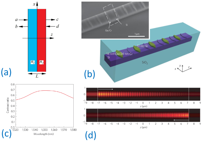
A simple two-layer structure shown in Fig. 22 represents a basic, exactly solvable, and experimentally realizable system which can realize invisibility [103]. Infinite planar slab of optically active material consists of two layers having complex refractive indices and and equal thickness of . The wave equation for a linearly polarized time-harmonic electromagnetic wave that propagates along the direction normal to the slab reads
| (51) |
where
| (52) |
The amplitudes of plane waves depicted in Fig. 22 (a) are related through a matrix
| (53) |
Particular cases of left-incident and right-incident scattering solutions can be written as [105]
| (54) |
and
| (55) |
where the incident, transmitted and reflected light intensities are , , and , respectively. The (complex) transmission and left/right reflection amplitudes can be determined by the elements of matrix (note that ) as follows
| (56) |
with defined by Eq. (16) in Ref. [103]. A spectral singularity appears whenever one can satisfy for a real , then the transmission and reflection amplitudes diverge. Then, the necessary and sufficient conditions for the unidirectional invisibility are found as
where
| (60) |
The two-layer slab is invisible from both directions provided that and are rational numbers, and the wavelength at which the device is invisible is such that is the half integer multiple of [103]. Moreover, existence of invisible configurations that remain practically reflectionless within a very wide spectral range was demonstrated [103].
Unidirectional invisibility can be also achieved for PT-symmetric locally periodic potentials describing Bragg gratings with active layers [42]
| (61) |
where , , , and are particular real parameters. It was then shown that invisibility can be achieved only for structure length below a certain threshold [106], and analytical solutions were derived in Ref. [107].
The invisibility phenomenon was demonstrated experimentally in Ref. [104]. The optical non-Hermitian parity-time system was fabricated with only absorptive media on the Si-on-insulator (SOI) platform, see Fig. 22(b). This structure effectively realized a parity-time-symmetric periodic potential according to Eq. (61), but in a lossy background. Accordingly, the transmission is attenuated, but unidirectional reflection can still be observed. Indeed, experimental measurements show large contrast for reflections for incidence from the left and right, see Fig. 22(c). The difference occurs due to distinct distributions of the electric field, which are visualized based on numerical modelling in Fig. 22(d).
Suchkov et al. have studied wave scattering on a domain wall introduced into a linear array composed of PT-symmetric dimers by switching the gain and loss in a half of the array [108]. The linear spectrum of the defect-free array includes high-frequency and low-frequency branches. The two major effects have been revealed: amplification of both reflected and transmitted waves and excitation of the reflected and transmitted low-frequency and high-frequency waves by the incident high-frequency and low-frequency waves, respectively.
General approach to scattering theory for optical PT-symmetric systems with a wide range of geometries beyond the one-dimensional setting has been discussed in a recent work by Schomerus [109]. In particular, it is demonstrated that in the presence of the magneto-optical effects the symmetry of optical device becomes important. In addition to the PT-symmetry, the -symmetry is introduced to account for the variants of the geometrical and time-reversal operations. The latter symmetry imposes the same spectral constraints as the former one but, generally speaking, a different condition on the magnetic field. Scattering theory is applied to study spectral features of the open optical systems possessing different symmetries. This leads to effective models that can be formulated in the energy domain (via Hamiltonians) and in the time domain (via time evolution operators) giving the information about the related energy and time scales.
5.2 Nonlinear nonreciprocity
Whereas transmission is known to be reciprocal in linear systems as discussed in the previous section, nonlinearity can lead to nonreciprocal transmission which depends on the direction of incidence, i.e. . Nonlinear systems can realize optical isolation by predominantly allowing only one-way transmission, i.e. it allows light to pass through, say, for left incidence, whereas it is blocked for light coming from the other side. Such nonlinear optical diode have been extensively investigated in conservative optical systems, however active PT structures can be used to dramatically reduce the optical power threshold for nonlinear nonreciprocity [110].
The effect of nonreciprocity was first observed experimentally for electric current transmission lines attached to PT-symmetric electronic circuit resonators playing the role of nonlinear scatterers [111, 112]. As a reference model, Bender et al. used coupled nonlinear electronic Van der Pol oscillators with anharmonic parts consisting of a complementary amplifier (gain) and a dissipative conductor (loss) combined to preserve PT-symmetry. A striking feature observed in measurements was that the transmittance from left to right differs from the transmittance from right to left. The phenomenon is most pronounced in the regions of the resonances distorted by the nonlinearity, around kHz. Furthermore, it was found that increasing the gain or loss parameter, maintains or even enhances the transmitted intensities while it leaves unaffected the resonance position. This has to be contrasted with other proposals of asymmetric transport which are based on conservative nonlinear schemes (see for example Ref. [113]), where increase of asymmetry leads to reduced transmittances.
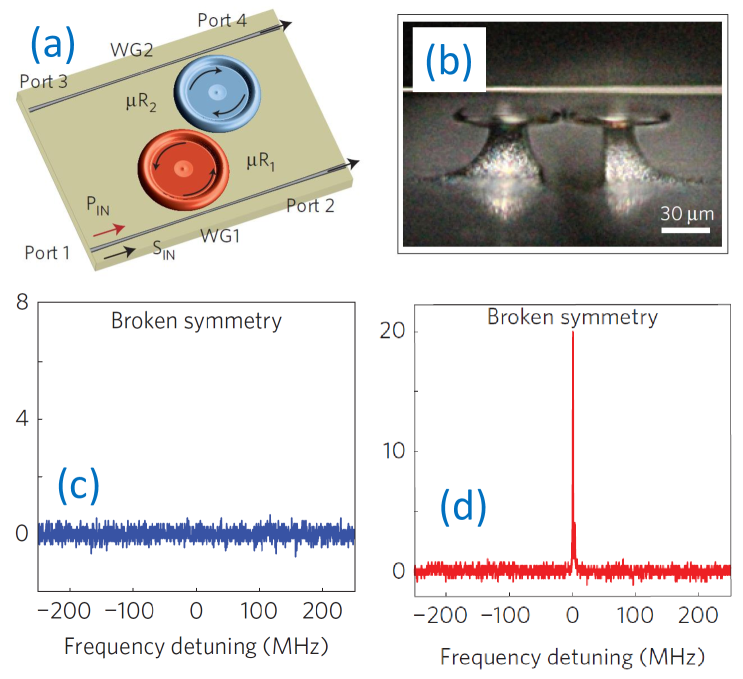
Nonreciprocal transmission in optics was observed in coupled-resonator structures, where nonlinear effects are enhanced due to strong field confinement [110]. The system was composed of two coupled microtoroidal whispering-gallery-mode resonators [Fig. 23(a)], where one was passive, and gain in the other one was provided in the 1,550nm wavelength band by optically pumping Er3+ ions with a pump laser in the 1,460nm band. The coupled-resonator system is PT symmetric because under parity reflection the resonators become interchanged and under time reversal loss becomes gain and gain becomes loss. The microtoroids were fabricated at the edges of two separate chips placed on nanopositioning systems to control precisely the distance and accordingly the coupling, see Fig. 23(b). For strong coupling, the modes are approximately PT-symmetric, whereas breaking of the mode symmetry is observed when the coupling is decreased beyond a critical value.
Transmission between ports 1 and 4 was monitored at different input power levels. At low powers the input-output relation was linear and the system was reciprocal in both the broken- and unbroken-symmetry phases. Indeed, a linear static dielectric system, even with gain and loss, can not have non-reciprocal response. At higher input powers, the system remained in the linear regime for the unbroken-symmetry phase. However the nonlinear threshold was lower in the broken-symmetry phase, due to the stronger field localization in the resonator with gain. As a result, nonlinear non-reciprocal effect was observed: the input signal at port 4 was transmitted to port 1 at resonance [Fig. 23(d)], but the input signal at port 1 could not be transmitted to port 4 [Fig. 23(c)]. The advantages of the PT microresonator systems for the realisation of nonreciprocal transmission include a significant reduction in the input power to 1 W and higher contrast with a complete absence of the signal in one direction but resonantly enhanced transmission in the other direction.
PT-symmetric structures based on microresonators can also be used to realize nonlinear Fano resonances that may give rise to ultralow-power and high-contrast switching and non-reciprocity due to their sharp asymmetric line shapes [27, 114]. Miroshnichenko et al. have considered an optical PT-symmetric gain/loss nonlinear dimer coupled to a passive chain transmitting linear discrete waves , as shown in Fig. 24(a) [27]. Propagation of light in this system can be described by the following set of discrete nonlinear Schrödinger equations
| (62) | |||||
| (63) | |||||
| (64) |
where the overdot stands for the time derivative, accounts for the linear gain and loss acting on complex variables and , respectively, is a frequency shift, accounts for the PT-symmetric nonlinear loss and gain (as shown in [27], stable eigenstates are obtained with , i.e., if the nonlinear loss competes with the linear gain and vice versa), is the coupling constant in the linear chain, is a coupling coefficient between the dimer and the chain, and for . Due to the symmetry, wave scattering in this system does not depend on the side of incidence.
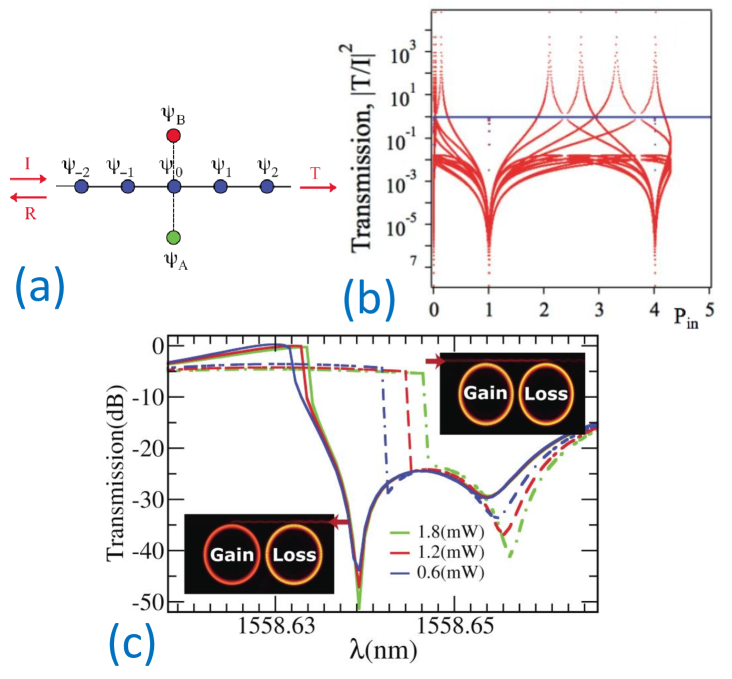
The solution corresponding to the scattering of incident waves with amplitude on the PT complex is looked for as
| (65) |
where wave number is determined by the dispersion equation for the linear chain, , while and are the amplitudes of the reflected and transmitted waves.
In the nonlinear regime with , one can find symmetric solutions with , where is real. For , the symmetric mode exists at , with determined by the equation
| (66) |
which yields a single real root for , and three real solutions (tristability) in the opposite case. All these solutions realize the perfect transmissivity with [the horizontal blue line in Fig. 24(b)].
In contrast to its linear counterpart, the nonlinear system may support complete suppression of the transmission (), that is, nonlinear Fano resonances [115]. The nonlinear PT-symmetric scatterer attached to the linear chain as shown in Fig. 24(a) can support a continuous family of symmetric nonlinear Fano resonances with (for the details see [27]). The family of the nonlinear Fano resonances with the symmetrically excited side-coupled PT elements exists in an interval of the intensity of the incident wave , even though Fano resonance is usually obtained as an isolated solution.
It was further suggested that nonlinear nonreciprocity and optical isolation through Fano resonances can be realized with two nonlinear micro-resonators with gain and loss are coupled to a single waveguide [114]. In the nonlinear regime, the line-shape and Fano resonance position depends on the direction of the incident light, which can provide nonreciprocal transmission with 47 dBs contrast in the optical C-window around 1.55m optical wavelength.
Scattering of linear waves propagating in a waveguide array with an embedded nonlinear PT-symmetric dimer was found to demonstrated distinct features [116]. It was found that, under certain conditions, nonlinearity can effectively suppress the nonconservative effects, which are generated by the linear gain and loss terms. In particular, at high intensities, the incident wave can almost entirely transmit across the defect.
Linear PT-symmetric systems can demonstrate spectral singularities leading to infinite transmission and reflection coefficients [105]. Divergence of the fields in the medium breaks the assumptions of the linear analysis and requires taking into account the dependence of the refractive index of medium on the light intensity. It was observed that simplest cubic Kerr-type nonlinearity does not lead to regularization of spectral singularities [117] but the saturable nonlinearity does [118].
5.3 Soliton scattering
Collision of moving solitons with localized obstacles (defects) is the problem of fundamental significance in various nonlinear wave guiding systems. Recently in nonlinear optics a great deal of attention has been focused on the effect of soliton interaction with the complex PT-symmetric localized potentials embedded into the self-focusing or self-defocusing medium. In these settings the PT-symmetric gain and loss regions are spatially localized, e.g, in the form of nonlinear PT-symmetric dimers, trimers, or, more generally, oligomers embedded into nonlinear conservative lattice [119, 120, 44, 116]. Continuum versions of such models have been analyzed in the works [121, 122, 123]. In other cases soliton dynamics is investigated in the two-core systems such as an array of coupled PT-symmetric dimers [65, 124] and its continuum version in the form of coupled planar waveguides with gain in one of them and balanced loss in another [59, 125]. Two-dimensional generalization of such models was studied in [126].
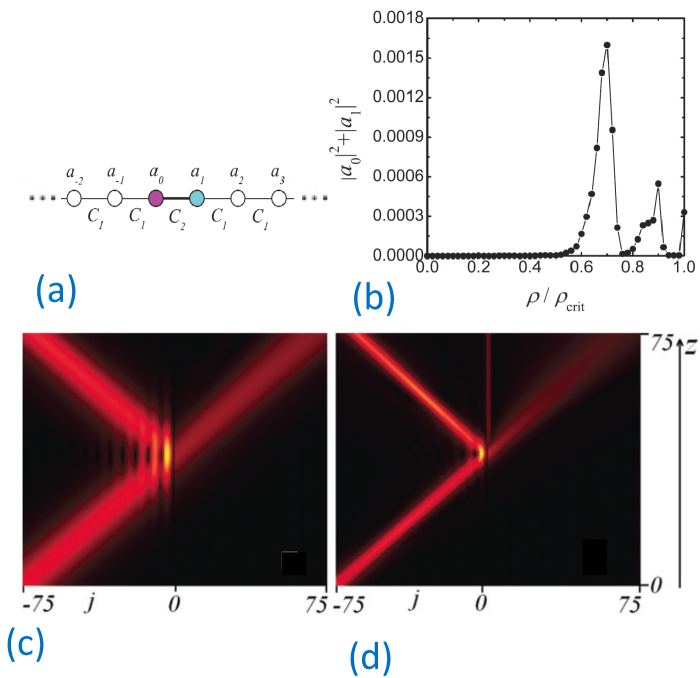
Soliton scattering by PT defects was first investigated in a nonlinear waveguide array [119, 120]. A local inhomogeneity was created by a pair of PT-symmetric waveguides with balanced gain and loss [see Fig. 25(a)]. Propagation of light in this system was modelled with the coupled discrete nonlinear Schrödinger equations
| (67) | |||||
| (68) | |||||
| (69) |
where the overdot stands for the derivative with respect to the propagation distance , is the waveguide number, are the mode amplitudes at waveguides, defines the rate of loss (gain) at zeroth and gain (loss) at first waveguides, and are the coupling coefficients between the modes of waveguides.
Far from the defect, i.e., for , Eq. (67) has an approximate soliton solution
which can be found by considering the continuum limit of Eq. (67) in the form of the integrable nonlinear Schrödinger equation. Here , , , , and are parameters defining the soliton amplitude, inverse width, velocity, initial position, and initial phase, respectively.
It was found that solitons can be partially reflected and transmitted by the PT defect, and the total energy is generally not conserved in the scattering process. In addition, the soliton can excite the mode localized at the PT-symmetric defect, and this process resonantly depends on the structure parameters including the gain and loss, as illustrated in Fig. 25(b). Example of soliton scattering without excitation of localized mode is shown in Fig. 25(c), whereas under different parameters mode excitation is clearly visible, see Fig. 25(d). The soliton interaction with the large-amplitude localized mode can result in PT-symmetry breaking [120].
Interestingly, a discrete model describing a waveguide array with energy gain and loss that admits exact solitary wave solutions has been found [124]. Existence of the high-frequency and the low-frequency solitons was demonstrated. The numerical study of collisions between similar and dissimilar solitons has demonstrated that solitons of the same type interact elastically, while for the dissimilar ones the collision outcome significantly depends on the initial conditions.
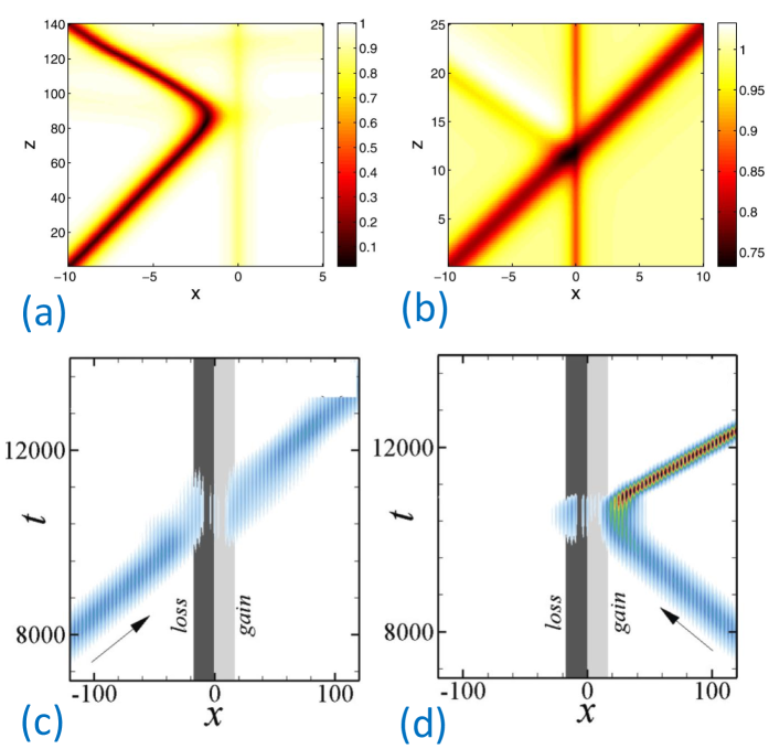
Karjanto et al. [123] have studied the scattering of bright and dark solitons on a strongly localized PT-symmetric defect in frame of the nonlinear Schrödinger equation for the local amplitude of the electromagnetic wave, ,
| (71) |
with a complex potential:
| (72) |
where and denote the Dirac delta function and its derivative, and being real constants, positive or negative [123]. The nonlinear term in Eq. (71) represents defocusing nonlinearity for .
The collisions of incident dark soliton with the PT-symmetric defect were simulated, setting the initial conditions as
| (73) |
where is the initial soliton position and is its velocity. Shown in Figs. 26(a,b) are the examples of the interaction of the dark solitons with the defect for the cases of defocusing nonlinearity. In case (a) the soliton initial velocity is relatively small, and it is reflected by the defect. In case (b) the soliton velocity is relatively large, and it passes through the defect. An essential difference from previously studied interactions of solitons with defects in conservative systems is that, in spite of the gain-loss balance in the PT-symmetric dipole, the collisions change the norm of the solitons making the interaction dynamics more complex.
Abdullaev et al. [122] studied scattering of gap solitons by PT defects in the framework of the following model,
| (74) | |||||
| (75) | |||||
| (76) |
that includes the periodic potential (optical lattice) with the amplitude and the PT-symmetric localized defect that introduces gain and loss in the system. Here is the strength of the conservative part of the defect, coefficient stands for the gain-dissipation parameter, while the width of the defect is fixed to in all numerical calculations. In the absence of the defect potential, Eq. (74) possesses families of exact gap soliton solutions. It is shown that by properly designing the amplitudes of real and imaginary parts of the PT defect it is possible to achieve a resonant transmission of the gap solitons through the defect. This phenomenon occurs for potential parameters that support localized modes inside the PT defect potential with the same energy and norm of the incoming soliton. When the imaginary amplitude of the PT defect is increased, the possibility of damping or amplification of transmitted or reflected gap soliton is demonstrated depending on the soliton incidence direction. Furthermore, unidirectional transmission or diode effect can be achieved as illustrated in Figs. 26(c,d). A pair of PT defects with oppositely positions gain and loss layers can then be used to trap a gap soliton.
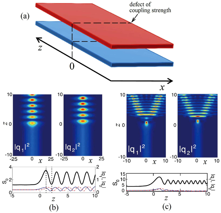
Soliton scattering on a defect in the two-core system schematically shown in Fig. 27(a) was studied by Bludov et al. [125]. The defect is introduced in the planar PT-symmetric coupled waveguides with gain (top waveguide) and loss (bottom waveguide) by local modification of the coupling constant in the vicinity of . Light propagation in this system can be described by the two coupled nonlinear Schrödinger equations
| (77) | |||||
| (78) | |||||
| (79) |
The coupling coefficient attains the minimal value at and tends to at . The defect of coupling has the width . Far from the defect () one has , and the model supports symmetric and antisymmetric types of soliton solutions as described above. Examples the of the soliton-defect interactions are presented for the cases of symmetric and antisymmetric solitons in Figs. 27(b) and (c), respectively. Upper panels give the field intensities, while lower panels present the respective evolution of the total energy flow (thick solid lines) and soliton amplitudes and (thin solid and dashed lines, respectively). In Fig. 27(b), the soliton passes through a relatively short defect () transforming into a breather, which is characterized by the intensity oscillations between the two components: minimum (maximum) in one component corresponds to maximum (minimum) in the other. In Fig. 27(c), for the splitting of the incident soliton in the two outward propagating pulses is observed. There also exist other scenarios of the soliton-defect interactions as discussed in Ref. [125].
6 Periodically Modulated Systems
Periodic modulation is an effective tool for controlling tunneling dynamics [127, 128, 129, 130, 131]. In recent years the PT symmetry of the periodically modulated systems have attracted increasing attention.
6.1 Modulated waveguide couplers
Modulation of structure parameters along the propagation direction of coupled optical waveguides with gain and loss can open new opportunities for optical signal control in both linear [132, 133, 134] and nonlinear [62, 135, 136, 137, 138, 50] regimes.
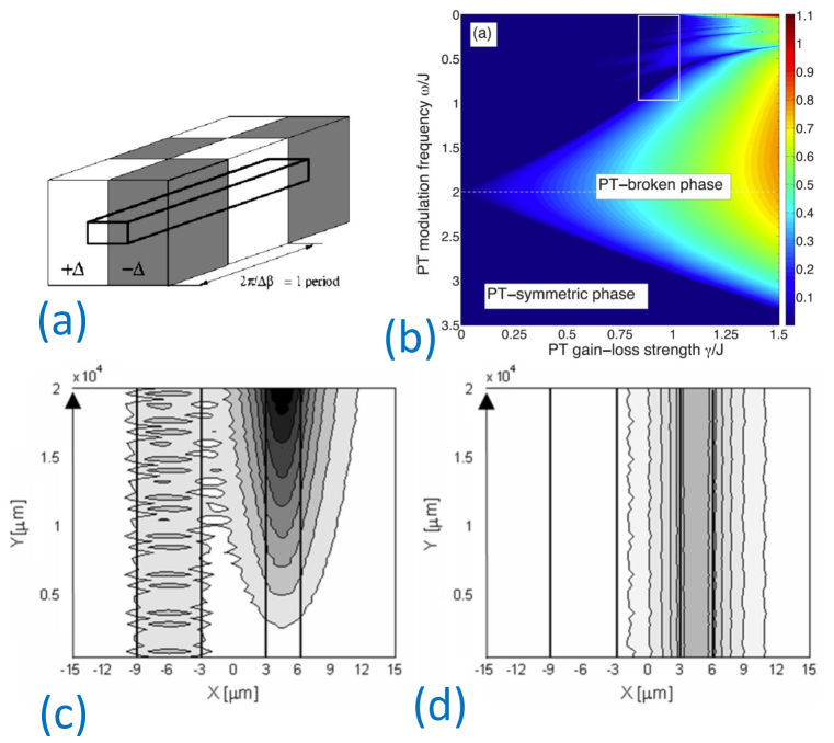
Interestingly, the first studies of couplers with modulated loss and gain were carried out without a consideration of PT symmetry [139, 141, 140, 142]. In these studies, it was shown that unidirectional energy transfer between co-propagating optical modes can be achieved in waveguides with longitudinally modulated gain and loss regions. An example of a two-mode active coupler is shown in Fig. 28(a). Examples of unidirectional behaviour are presented in Figs. 28(c,d), where light gets localized and amplified in the right waveguide, irrespective of the input coupling port. Such irreversible coupling between the co-propagating modes cannot be achieved in conservative structures. This phenomenon relies on the breaking of the time-reversal symmetry through the modulation of the complex optical refractive index, being analogous to unidirectional scattering by PT-symmetric Bragg gratings discussed in Sec. 5.1.
Light evolution in modulated two-mode couplers can be described within a framework of coupled-mode theory,
| (80) |
where is the propagation distance along the waveguide, are the mode amplitudes, is the coupling coefficient, are the gain/loss coefficients, are the real propagation constants, and is the mode number. Such type of models were found to possess PT symmetry, under certain restrictions on the modulation profiles [132, 133, 134].
The formulation of Eq. (80) is not unique, and it depends on the choice of the basis modes. For the structure presented in Fig. 28(a), if the mode amplitudes are chosen as and , where correspond to symmetric and antisymmetric supermodes in the absence of gain or loss, we have , , . Such model is PT-symmetric in case of even modulation, . PT diagram for harmonic modulation, was calculated in Ref. [133], see Fig. 28(b). In PT-symmetric regime, average amplification is zero, however in PT-broken case, one mode experiences strong amplification. Boundaries between these regimes depend nontrivially both on the modulation amplitude and frequency. In case of resonant modulation amplitude matching the beating period between the modes, which corresponds to the normalized value “2” along the vertical axis in Fig. 28(b), PT mode symmetry is broken for arbitrarily small values of gain/loss modulation. It is in this regime that unidirectional mode coupling is always realized, as illustrated in Figs. 28(a,c,d). This is a key difference from unmodulated linear PT couplers, where PT breaking occurs only above a certain threshold of gain/loss.
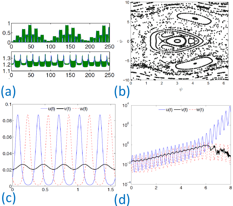
Nonlinear optical interactions can have a nontrivial effect on the mode evolution. It was shown that local Kerr-type nonlinearity can preserve or change the stability properties. Of particular interest is the regime when the system is unstable in the linear regime, but becomes stable due to conservative nonlinear self-action, as illustrated in Fig. 29(a). Such stabilising effect can enable design of laser sources, similar to the case of actively coupled PT waveguides with fixed parameters discussed in Sec. 2.3, however periodic modulation can be realized in a simple way whily allowing fine control over the emerging nonlinear dynamics, which can be periodic or aperiodic. Indeed, chaotic evolution was predicted for a coupler (dimer) with periodically modulated gain and loss [138]. This is illustrated in Fig. 29(b), where the phase plane is presented for variables , with . Periodic modulation can be further applied to multiple coupled nonlinear waveguides, or oligomers [136, 50]. Examples of stable periodic and unstable dynamics in a nonlinear trimer with periodically modulated gain and loss are show in Figs. 29(c) and (d), respectively. Furthermore, periodic modulation can stabilize temporal solitons in coupled waveguides, in the supersymmetric regime when loss and gain are at the linear PT breaking threshold [135].
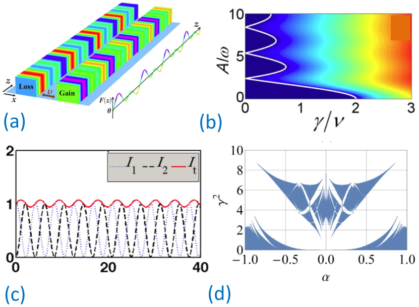
When system parameters are modulated such that underlying system is not PT-symmetric at any modulation cross-section, the overall dynamics can still demonstrate the features of pseudo-PT symmetry [143]. The concept of pseudo-PT symmetry corresponds to the PT-symmetry in the effective system, which manifests as quasi-stationary propagation. Such regime can be achieved under high-frequency periodic modulation, when the modulated system can be mapped into an effectively unmodulated one with rescaled parameters. Following Ref. [143], consider a coupler described by Eq. (80) with balanced gain and loss, and , fixed coupling , and modulated propagation constants , . A biharmonic modulation was analyzed, . For , the corresponding Hamiltonian is not PT-symmetric. Nevertheless, the averaged system obtained after averaging the high-frequency modulations features PT symmetry, and the quasi-energies for such effective system are found as
| (81) |
with the rescaled coupling strength
| (82) |
The two quasi-energies are real if , and they are complex if with the critical point . There exists a spontaneous PT-symmetry-breaking transition in the effective system when the imaginary part changes from zero to nonzero, as illustrated in Fig. 30(b). It appears surprising that the quasi-energies can be real even when the modulated system (80) is non-PT-symmetric, however the numerical analysis reveals that the eigenvalues of the original modulated structure have a very small but nonzero imaginary part. Accordingly, at intermediate propagation distances the dynamics can be almost exactly periodic in the quasi-PT symmetric regime, as show in Fig. 30(c).
Further interesting possibilities can arise in case of aperiodic driving. It was found that a phase diagram analogous to Hofstadter’s butterfly spectrum can emerge in PT Hamiltonians [134], see Fig. 30(d). The horizontal axis in the plot corresponds to the ration of two driving frequencies, and the vertical axis characterizes detuning between the modes.
6.2 Modulated lattices
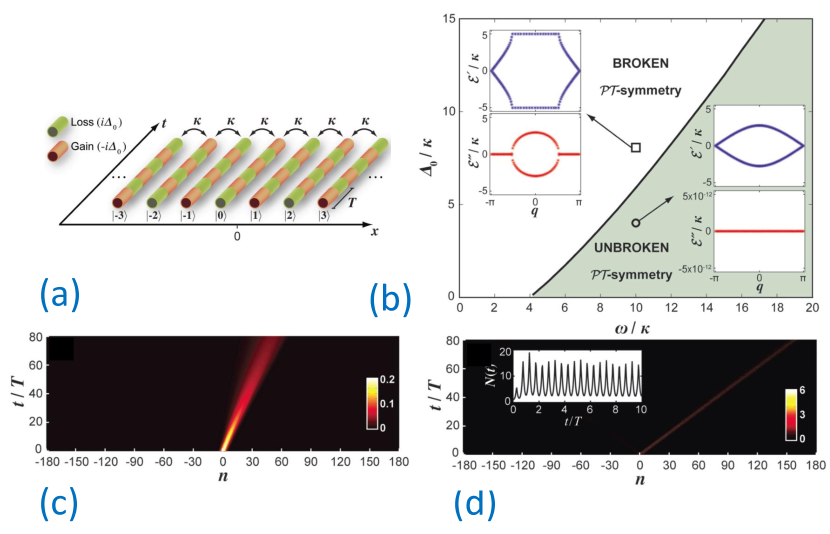
Arrays of coupled modulated waveguides with gain and loss open new opportunities to control the rate of beam propagation and spreading through the lattice [144]. Detailed theoretical analysis was performed for a lattice with periodic modulation of gain and loss, which is out-of-phase between the neighbouring waveguides as illustrated in Fig. 31(a). Linear beam evolution in such arrays is described by the coupled-mode equations,
| (83) |
where is the waveguide number, are the mode amplitudes, is the propagation coordinate, is the coupling between the neighbouring waveguides, and is a square modulation profile of gain and loss. Solutions of this system can be found analytically in Fourier space, characterized by the transverse wavenumber . For a range of modulation parameters indicated with shading in Fig. 31(b), the eigenmodes with all have unbroken PT symmetry. Outside of this parameter region, some modes have broken PT symmetry. Characteristic dispersion dependencies corresponding to these two regimes are shown as insets in Fig. 31(b). The imaginary part at the lower insets represents the mode gain or loss, and we see that it is zero for all modes in the unbroken PT regime. The real part shown in the upper insets defines the propagation angle (proportional to the first derivative) and strength of diffraction (proportional to the second derivative). It is seen that these propagation characteristics can be very strongly affected due to PT transition. A comparison of beam propagation in a conservative array and array with gain/loss modulation parameters chosen close to PT threshold are presented in Figs. 31(c) and (d), respectively. The input beam is inclined such that the phase gradient between the neighbouring waveguides is , which corresponds to the fastest propagation across a conventional conservative lattice, limited by the coupling rate [Fig. 31(c)]. However in a PT lattice with modulated gain and loss, hyper-ballistic transport can be realised with much higher propagation velocity [Fig. 31(c)]. Additionally, the beam spreading due to diffraction is strongly reduced.
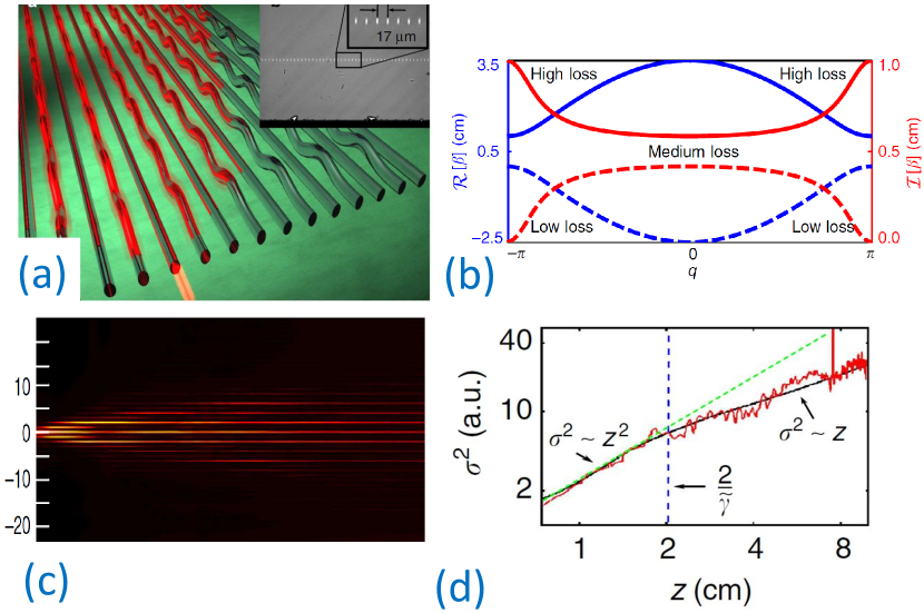
Experimental realisation of PT lattices based on fs laser-written modulated conservative waveguides was reported in Ref. [145]. As shown in Fig. 32, every second waveguide was periodically curved, which resulted in bending losses. In the regime of high-frequency modulation, the loss can be considered as effectively constant along the waveguides. The corresponding spectrum of eigenmodes is presented in Fig. 32(b). Eigenmodes in different regions of the spectrum will experience different losses, depending on the value of the imaginary part of their propagation constant. As a consequence, in both bands modes in the centre of the spectrum (where ) experience an intermediate loss, which is close to the average loss in the system. At the edge of the spectrum (around ), the modes in the upper band suffer from a loss that is much higher than the systems’s average loss, whereas in the lower band the modes experience much less loss. Hence, because of decay, the modes in the upper band at the edge of the spectrum will disappear after a relatively short propagation distance z, whereas the modes in the centre of the spectrum will disappear somewhat later. Therefore, at long propagation distances. the spectrum will be getting narrower, and only a part of the spectrum will contribute to transport. Experimental image of the beam propagation is presented in Fig. 32(c), and Fig. 32(d) presents the beam variance characterising its width, . It is observed that initially, the wave exhibits ballistic spreading with , as all eigenmodes still contribute to the transverse. transport. However after , transition from ballistic to diffusive transport is visible, with slower beam spreading as . Such coexistence of ballistic and diffusive transport in a static, ordered system, could only happen due to non-Hermitically. More recently, topological phase transition was reported in such waveguide arrays [146].
The unconventional properties of modulated PT lattices based on waveguide arrays suggest that such systems would demonstrate novel features in the nonlinear regime, and we anticipate theoretical and experimental studies targeting these topics in the near future. In particulatr, due to the flexibility of waveguide array writing with fs lasers [147], this platform could enable the observation of linear and nonlinear effects in modulated PT structures.
6.3 Mesh lattices
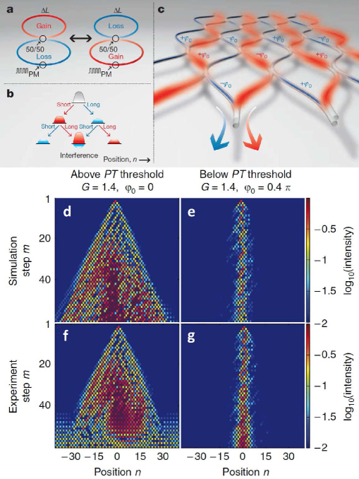
Regensburger et al. [148] demonstrated the first experimental realization of a large-scale PT-symmetric lattice, which was a new kind of optical PT synthetic devices. They reported the experimental observation of light transport in large-scale temporal lattices which are parity-time symmetric. In addition, the periodic structures respecting PT symmetry can act as unidirectional invisible media when operated near their exceptional points.
To realize the specially artificial structures and study the light transportation, they have used an elegant experimental arrangement that operates in the temporal domain, see Fig. 33 (a) and (b). In most cases, the refractive index is a complex quantity. The real part of the refractive index affects the velocity of the propagating light, while the imaginary part can lead to the amplification or absorbtion of light within a material. By temporally modulating the real and imaginary part of the refractive index, they were able to realize the PT-symmetric optical network in the temporal domain, whose system is analogous to a spatially periodic mesh network with gain and loss. Each node of the spatial network corresponds to a specific ’time slot’ of the temporal lattice, see Fig. 33 (c). A sequence of light pulses are injected into two connected optical fiber loops that are designed to exhibit PT symmetry. The anti-symmetric imaginary part of refractive index profile is attained by alternating gain and loss in the two loops via using optical amplifiers and amplitude modulators. While the even, real component of the index profile is introduced by using phase modulators.
The observation of the unusual unidirectional invisibility in their system is also interesting. Since the left-right symmetry is broken in this structure and propagation is no longer invariant when gain and loss are exchanged in time. More specifically, light propagating in such a system can experience reduced or enhanced reflections dependent on the direction of propagation while it has little effect on the transmitted light. The system can become totally invisible when light traverses it from one side, whereas it can still be seen when it is illuminated from the other.
In Ref. [150], they investigated a class of optical mesh periodic structures that are discretized in both the transverse and longitudinal directions, which is equivalent to the above ones in the temporal domain. The mesh arrangements are composed of an array of waveguides with each one being discretely and periodically coupled to its adjacent neighbors. The practical appealing of this type of lattice is the physical separation between the coupling and amplification within each building block. And the band structure of these systems have been systematically analyzed and their dispersion relation is analytically obtained. And the optical dynamics including the unidirectional invisibility in these PT-symmetric mesh lattices are also examined.
By introducing nonlinearity, the observation of stable optical discrete solitons in the PT-symmetric mesh lattices system has been experimentally demonstrated [149]. The structure of lattices is the same as shown in Fig. 33 (c), which is globally PT-symmetric. In the linear regime, when a single position is excited, the wavepacket spreading experiences a great amplification in the broken PT-symmetry regime and remains neutral below the PT threshold. Interestingly, when the power of single initial pulse is raised, the nonlinearity comes into play and the discrete solitons may appear in the system. Above the PT threshold, the nonlinearity cannot lead to stable solitary waves and the wavepacket still spreads exponentially, see Fig. 33 (d) and (f). However, below the PT threshold, the nonlinearity can compensate the spreading and the optical soliton appear, see Fig. 33 (e) and (g). It has been demonstrated that these solitons belong to a continuous family of solitons which is not typically the case for dissipative solitary waves and this class of discrete solitons can avoid instabilities. Based on such mesh lattices system, the behavior of nonlinear waves provides a possibility for realizing saturable absorbers which are widely used in Q-switched laser cavities and ultra-short optical pulse arrangements.
These results, obtained for both temporal and spatial modulated systems, represent an important step towards applications of the parity-time symmetry concept to a new generation of multi-functional optical devices and networks.
7 Conclusion and outlook
Future technologies will demand a substantial increase in a density of photonic integration and energy efficiency far surpassing that of bulk optical components and modern silicon photonics. Such advances can be achieved only by embedding the photonic functionalities at material’s level taking advantages of subwavelength nanophotonics and metadevices. Many metadevices based on plasmonic technologies would require an engineered loss compensation that, as we expect, can be achieved in a clever way through the concepts of non-Hermitian dynamics and the PT symmetric photonic systems. It is believed that the PT symmetric photonic systems can offer promising solutions of a range of important problems providing an efficient and smart loss compensation. Photonic PT systems feature alternating and symmetrically distributed regions of gain and loss, and in such systems losses are as important as gain so that, depending on the structural parameters, gain can either compensate losses or amplify optical pulses. In addition, tunable photonic PT-symmetric systems can add many new exciting functionalities being potentially able to find even broader applications beyond the field of photonics, e.g. in the field of Bose-Einstein condensates [151]. Also, the soliton scattering on PT-symmetric defects has been studied for otehr types of models, for example for the Klein-Gordon system [152, 153].
As an example of the most recent developments we mention a very general study of constant-intensity waves in non-Hermitian potentials. It is well known that any finite-amplitude wave propagating in a nonlinear system undergoes modulational instability in any Hermitian potential with self-focusing nonlinearity. Markis et al. [154] demonstrated that this fundamental restriction is conveniently lifted when working with non-Hermitian potentials. In particular, they presented a whole class of waves that have constant intensity in the presence of linear and nonlinear inhomogeneous media with gain and loss. These results suggest new directions for the experiments on nonlinear non-Hermitian scattering.
Many recent developments on non-Hermitian and PT symmetric systems occur beyond the field of photonics, and one of the examples is exciton-polariton condensate which is composed of hybrid light-matter quasiparticles formed by strongly interacting photons and excitons (electron-hole pairs) in semiconductor microcavities. The exciton-polaritons always exist in a balanced potential landscape of gain and loss and, as was shown recently [155], the non-Hermitian nature of the system can modify dramatically the structure of modes and spectral degeneracies in exciton-polariton systems, and, therefore, will affect their quantum transport, localisation, and dynamical properties. These findings pave the way for studies of non-Hermitian quantum dynamics of exciton-polaritons, which can uncover novel operating principles for polariton-based devices.
As discussed above, PT symmetric systems demonstrate many nontrivial non-conservative wave interaction and phase transitions, which can be employed for signal filtering and switching, opening new prospects for active control of light. In this review, we have discussed only some problems involving nonlinear PT-symmetric photonic systems with an intensity-depend refractive index. Nonlinearity in such PT symmetric systems provides a basis for many effects such as formation of localized modes, nonlinearly induced PT-symmetry breaking, and all-optical switching of signals. Nonlinear PT-symmetric systems can serve as powerful building blocks for the development of novel photonic devices targeting an active light control.
As follows from the results summarized above, the study of photonic systems with the PT symmetry is an active research area which is expanding very rapidly leaving the boundaries outlined by the photonic systems and penetrating to other fields such as the physics of Bose-Einstein condensates. However, the photonics is a cornerstone of those research due to rapidly expanding experimental demonstrations. Here, we have reviewed only a few of many intriguing properties and applications of PT-symmetric photonics systems being concentrated on the less studied nonlinear properties, but the field is quickly growing and many new ideas and demonstrations appear almost every week.
S.V.S., A.A.S., and Y.S.K. were supported by the Australian Research Council, including Discovery Project DP130100135 and Future Fellowship FT100100160. S.V.S. and S.V.D. acknowledge financial support from the Russian Foundation for Basic Research, grant No mol_a, and the D.I. Mendeleev fund of the Tomsk State University. C. Lee and J. Huang are supported by the National Basic Research Program of China (NBRPC) under Grant No. 2012CB821305 and the National Natural Science Foundation of China (NNSFC) under Grants No. 11374375.
cvSuchkovSergey V. Suchkovgraduated from Ufa State Aviation Technical University, Ufa, Russia in 2009. After his graduation he worked as an engineer researcher at the Institute for Metals Superplasticity problems of RAS, Ufa. In 2014 he joined the Nonlinear Physics Centre at Australian National University where he is currently carrying out his research as a PhD student. The area of interests includes optical microresonators, nonlinear -symmetric systems, discrete nonlinear models. \authorboxcvSukhorukovAndrey A. Sukhorukovgraduated from the Physics Faculty of the Lomonosov Moscow State University, Russia and received Ph.D. degree in physics from the Australian National University (ANU) in 2002. He currently leads Nonlinear and Quantum Optics Group at the Nonlinear Physics Centre, ANU. His research interests include nonlinear optical switching, frequency conversion, generation of non-classical states of light, and opto-mechanical interactions in waveguides and nano-structures. He received Queen Elizabeth II and Future Felowships from the Australian Research Council and Humboldt Research Fellowship. \authorboxcvHuangJiahao Huanggraduated from the School of Physics and Engineering, Sun Yat-Sen University (Guangzhou, China). Currently he is a PhD student at the same school. During his PhD, he performed several theoretical studies in quantum metrology and quantum simulation. His research interests include quantum-optical analog in optical waveguides and quantum metrology with ultracold atoms. \authorboxcvDmitrievSergey V. Dmitrievwas born in 1961 in Tomsk, Russia. S.V. Dmitriev graduated from Tomsk State University with a M.S. degree in 1984. Completed the PhD degree in structural mechanics at Tver State University, Russia, in 1988. Gained the second PhD degree in computer modeling of incommensurate phases in dielectrics from the University of Electro-Communications, Tokyo, Japan, in 1999. Received a Habilitation in 2008 with the thesis on solitary wave dynamics in discrete systems from the Altai State Technical University, Barnaul, Russia. Since 2008, S.V. Dmitriev has been serving as the Head of Laboratory of the Institute for Metals Superplasticity Problems, Ufa, Russia. His scientific interests are in solitary waves in discrete systems; discrete breathers; evolution of defect structures in solids during plastic deformation; mechanical properties of graphene; atomistic simulations \authorboxcvLeeChaohong Leereceived a PhD degree in atomic and molecular physics in 2003 from the Wuhan Institute of Physics and Mathematics, Chinese Academy of Sciences (Wuhan, China). From 2003 to 2009 he worked in the Max Planck Institute for the Physics of Complex Systems (Dresden, Genmany) and the Australian National University (Canberra, Australia). In 2009, he joined the Sun Yat-Sen University (Guangzhou, China) as a full professor and established a research group on cold atomic physics and quantum technologies. His research activities span over several branches of quantum atomic gases and quantum photonics, including nonlinear matter-waves, macroscopic quantum phenomena, many-body-quantum physics, non-equilibrium quantum dynamics, quantum metrology, and quantum simulation. \authorboxcvKivsharYuri S. Kivsharreceived a PhD degree in theoretical physics in 1984 from the Institute for Low Temperature Physics and Engineering (Kharkov, Ukraine). From 1988 to 1993 he worked at different research centers in USA, France, Spain, and Germany, and in 1993 he moved to the Australian National University (ANU) where he founded Nonlinear Physics Center being currently its Head and ANU Distinguished Professor. His research interests include nonlinear photonics, optical solitons, nanophotonics, and metamaterials. He is Fellow of the Australian Academy of Science, the Optical Society of America, the American Physical Society, the Institute of Physics (UK), Deputy Director of the Center of Excellence for Ultrahigh-bandwidth Devices for Optical Systems CUDOS (Australia) and Research Director of Metamaterial Laboratory (Russia). He received many prestigious international awards including the Lyle Medal of the Australian Academy of Science (Australia), the State Prize in Science and Technology (Ukraine), the Lebedev Medal of the International Rozhdestvensky Society (Russia), and the Harrie Massey Medal of the Institute of Physics (UK).
References
- [1] C. M. Bender and S. Boettcher, Real spectra in non-hermitian hamiltonians having PT symmetry, Phys. Rev. Lett. 80, 5243–5246 (1998).
- [2] C. M. Bender, D. C. Brody, and H. F. Jones, Complex extension of quantum mechanics, Phys. Rev. Lett. 89, 270401–4 (2002).
- [3] C. M. Bender, Making sense of non-hermitian hamiltonians, Rep. Prog. Phys. 70, 947–1018 (2007).
- [4] A. Ruschhaupt, F. Delgado, and J. G. Muga, Physical realization of PT-symmetric potential scattering in a planar slab waveguide, J. Phys. A 38, L171–L176 (2005).
- [5] R. El Ganainy, K. G. Makris, D. N. Christodoulides, and Z. H. Musslimani, Theory of coupled optical PT-symmetric structures, Opt. Lett. 32, 2632–2634 (2007).
- [6] C. E. Ruter, K. G. Makris, R. El Ganainy, D. N. Christodoulides, M. Segev, and D. Kip, Observation of parity-time symmetry in optics, Nature Physics 6, 192–195 (2010).
- [7] A. Guo, G. J. Salamo, D. Duchesne, R. Morandotti, M. Volatier-Ravat, V. Aimez, G. A. Siviloglou, and D. N. Christodoulides, Observation of PT-symmetry breaking in complex optical potentials, Phys. Rev. Lett. 103, 093902–4 (2009).
- [8] L. Feng, Z. J. Wong, R. M. Ma, Y. Wang, and X. Zhang, Single-mode laser by parity-time symmetry breaking, Science 346, 972–975 (2014).
- [9] H. Hodaei, M. A. Miri, M. Heinrich, D. N. Christodoulides, and M. Khajavikhan, Parity-time-symmetric microring lasers, Science 346, 975–978 (2014).
- [10] A. A. Zyablovsky, A. P. Vinogradov, A. A. Pukhov, A. V. Dorofeenko, and A. A. Lisyansky, PT-symmetry in optics, Phys. Usp. 57, 1063–1082 (2014).
- [11] Y. J. Chen, A. W. Snyder, and D. N. Payne, Twin core nonlinear couplers with gain and loss, IEEE J. Quantum Electron. 28, 239–245 (1992).
- [12] B. A. Malomed, G. D. Peng, and P. L. Chu, Nonlinear-optical amplifier based on a dual-core fiber, Opt. Lett. 21, 330–332 (1996).
- [13] Y. S. Kivshar and G. P. Agrawal, Optical Solitons: From Fibers to Photonic Crystals (Academic Press, San Diego, 2003).
- [14] N. N. Rosanov, Spatial Hysteresis and Optical Patterns, Springer Series in Synergetics (Springer, New York, 2002).
- [15] N. Akhmediev and A. Ankiewicz (eds.), Dissipative Solitons, Lecture Notes in Physics (Springer, New York, 2005).
- [16] H. Ramezani, T. Kottos, R. El Ganainy, and D. N. Christodoulides, Unidirectional nonlinear PT-symmetric optical structures, Phys. Rev. A 82, 043803–6 (2010).
- [17] A. A. Sukhorukov, Z. Y. Xu, and Y. S. Kivshar, Nonlinear suppression of time reversals in PT-symmetric optical couplers, Phys. Rev. A 82, 043818–5 (2010).
- [18] P. G. Kevrekidis, D. E. Pelinovsky, and D. Y. Tyugin, Nonlinear dynamics in PT-symmetric lattices, J. Phys. A 46, 365201–17 (2013).
- [19] I. V. Barashenkov, Hamiltonian formulation of the standard PT-symmetric nonlinear Schrödinger dimer, Phys. Rev. A 90, 045802–4 (2014).
- [20] I. V. Barashenkov, G. S. Jackson, and S. Flach, Blow-up regimes in the PT-symmetric coupler and the actively coupled dimer, Phys. Rev. A 88, 053817–8 (2013).
- [21] J. Pickton and H. Susanto, Integrability of PT-symmetric dimers, Phys. Rev. A 88, 063840–8 (2013).
- [22] I. V. Barashenkov, D. E. Pelinovsky, and P. Dubard, Dimer with gain and loss: Integrability and PT-symmetry restoration, J. Phys. A 48, 325201–28 (2015).
- [23] A. Lupu, H. Benisty, and A. Degiron, Using optical PT-symmetry for switching applications, Photonics Nanostruct.: Fundam. Appl. 12, 305–311 (2014).
- [24] J. Schindler, A. Li, M. C. Zheng, F. M. Ellis, and T. Kottos, Experimental study of active lrc circuits with PT symmetries, Phys. Rev. A 84, 040101–5 (2011).
- [25] J. Cuevas, P. G. Kevrekidis, A. Saxena, and A. Khare, PT-symmetric dimer of coupled nonlinear oscillators, Phys. Rev. A 88, 032108–11 (2013).
- [26] M. Duanmu, K. Li, R. L. Horne, P. G. Kevrekidis, and N. Whitaker, Linear and nonlinear parity-time-symmetric oligomers: a dynamical systems analysis, Philos. Trans. R. Soc. A 371, 20120171–19 (2013).
- [27] A. E. Miroshnichenko, B. A. Malomed, and Y. S. Kivshar, Nonlinearly PT-symmetric systems: Spontaneous symmetry breaking and transmission resonances, Phys. Rev. A 84, 012123–4 (2011).
- [28] D. A. Zezyulin, Y. V. Kartashov, and V. V. Konotop, Stability of solitons in PT-symmetric nonlinear potentials, Europhys. Lett. 96, 64003–6 (2011).
- [29] N. V. Alexeeva, I. V. Barashenkov, K. Rayanov, and S. Flach, Actively coupled optical waveguides, Phys. Rev. A 89, 013848–5 (2014).
- [30] I. V. Barashenkov and M. Gianfreda, An exactly solvable PT-symmetric dimer from a hamiltonian system of nonlinear oscillators with gain and loss, J. Phys. A 47, 282001–18 (2014).
- [31] A. K. Sarma, M. A. Miri, Z. H. Musslimani, and D. N. Christodoulides, Continuous and discrete Schrödinger systems with parity-time-symmetric nonlinearities, Phys. Rev. E 89, 052918–7 (2014).
- [32] F. C. Moreira, F. K. Abdullaev, V. V. Konotop, and A. V. Yulin, Localized modes in media with PT-symmetric localized potential, Phys. Rev. A 86, 053815–7 (2012).
- [33] K. Li, D. A. Zezyulin, P. G. Kevrekidis, V. V. Konotop, and F. K. Abdullaev, PT-symmetric coupler with nonlinearity, Phys. Rev. A 88, 053820–11 (2013).
- [34] R. W. Boyd, Nonlinear Optics, 3rd edition (Academic Press, San Diego, 2008).
- [35] D. A. Antonosyan, A. S. Solntsev, and A. A. Sukhorukov, Parity-time anti-symmetric parametric amplifier, arXiv 1506.02143 (2015).
- [36] E. N. Tsoy, S. S. Tadjimuratov, and F. K. Abdullaev, Beam propagation in gain-loss balanced waveguides, Opt. Commun. 285, 3441–3444 (2012).
- [37] H. Cartarius, D. Haag, D. Dast, and G. Wunner, Nonlinear Schrödinger equation for a PT-symmetric delta-function double well, J. Phys. A 45, 444008–15 (2012).
- [38] A. S. Rodrigues, K. Li, V. Achilleos, P. G. Kevrekidis, D. J. Frantzeskakis, and C. M. Bender, PT-symmetric double-well potentials revisited: bifurcations, stability and dynamics, Rom. Rep. Phys. 65, 5–26 (2013).
- [39] T. Mayteevarunyoo, B. A. Malomed, and A. Reoksabutr, Solvable model for solitons pinned to a parity-time-symmetric dipole, Phys. Rev. E 88, 022919–11 (2013).
- [40] S. V. Suchkov, S. V. Dmitriev, A. A. Sukhorukov, I. V. Barashenkov, E. R. Andriyanova, K. M. Badgetdinova, and Y. S. Kivshar, Phase sensitivity of light dynamics in PT-symmetric couplers, Appl. Phys. A 115, 443–447 (2014).
- [41] D. A. Zezyulin and V. V. Konotop, Nonlinear modes in the harmonic PT-symmetric potential, Phys. Rev. A 85, 043840–6 (2012).
- [42] Z. Lin, H. Ramezani, T. Eichelkraut, T. Kottos, H. Cao, and D. N. Christodoulides, Unidirectional invisibility induced by PT-symmetric periodic structures, Phys. Rev. Lett. 106, 213901–4 (2011).
- [43] K. Li and P. G. Kevrekidis, PT-symmetric oligomers: Analytical solutions, linear stability, and nonlinear dynamics, Phys. Rev. E 83, 066608–7 (2011).
- [44] J. D’Ambroise, P. G. Kevrekidis, and S. Lepri, Asymmetric wave propagation through nonlinear PT-symmetric oligomers, J. Phys. A 45, 444012–16 (2012).
- [45] D. A. Zezyulin and V. V. Konotop, Nonlinear modes in finite-dimensional PT-symmetric systems, Phys. Rev. Lett. 108, 213906–5 (2012).
- [46] K. Li, P. G. Kevrekidis, B. A. Malomed, and U. Gunther, Nonlinear PT-symmetric plaquettes, J. Phys. A 45, 444021–23 (2012).
- [47] O. Bendix, R. Fleischmann, T. Kottos, and B. Shapiro, Exponentially fragile PT symmetry in lattices with localized eigenmodes, Phys. Rev. Lett. 103, 030402–4 (2009).
- [48] D. E. Pelinovsky, D. A. Zezyulin, and V. V. Konotop, Nonlinear modes in a generalized PT-symmetric discrete nonlinear Schrödinger equation, J. Phys. A 47, 085204–20 (2014).
- [49] I. V. Barashenkov, L. Baker, and N. V. Alexeeva, PT-symmetry breaking in a necklace of coupled optical waveguides, Phys. Rev. A 87, 033819–5 (2013).
- [50] A. J. Martinez, M. I. Molina, S. K. Turitsyn, and Y. S. Kivshar, Nonlinear multicore waveguiding structures with balanced gain and loss, Phys. Rev. A 91, 023822–8 (2015).
- [51] K. Li, P. G. Kevrekidis, D. J. Frantzeskakis, C. E. Ruter, and D. Kip, Revisiting the PT-symmetric trimer: bifurcations, ghost states and associated dynamics, J. Phys. A 46, 375304–12 (2013).
- [52] D. Leykam, V. V. Konotop, and A. S. Desyatnikov, Discrete vortex solitons and parity time symmetry, Opt. Lett. 38, 371–373 (2013).
- [53] A. Mostafazadeh, Pseudo-hermiticity versus PT symmetry: The necessary condition for the reality of the spectrum of a non-hermitian hamiltonian, J. Math. Phys. 43, 205–214 (2002).
- [54] A. Mostafazadeh, Exact PT-symmetry is equivalent to hermiticity, J. Phys. A 36, 7081–7091 (2003).
- [55] K. Li, D. A. Zezyulin, V. V. Konotop, and P. G. Kevrekidis, Parity-time-symmetric optical coupler with birefringent arms, Phys. Rev. A 87, 033812–8 (2013).
- [56] H. Benisty, A. Lupu, and A. Degiron, Transverse periodic PT symmetry for modal demultiplexing in optical waveguides, Phys. Rev. A 91, 053825–11 (2015).
- [57] S. K. Turitsyn, A. M. Rubenchik, M. P. Fedoruk, and E. Tkachenko, Coherent propagation and energy transfer in low-dimension nonlinear arrays, Phys. Rev. A 86, 031804–4 (2012).
- [58] A. M. Rubenchik, E. V. Tkachenko, M. P. Fedoruk, and S. K. Turitsyn, Power-controlled phase-matching and instability of cw propagation in multicore optical fibers with a central core, Opt. Lett. 38, 4232–4235 (2013).
- [59] I. V. Barashenkov, S. V. Suchkov, A. A. Sukhorukov, S. V. Dmitriev, and Y. S. Kivshar, Breathers in PT-symmetric optical couplers, Phys. Rev. A 86, 053809–12 (2012).
- [60] A. T. Filippov, The Versatile Soliton, 2nd edition (Birkhäuser, Boston, 2010).
- [61] J. K. Yang, Necessity of PT symmetry for soliton families in one-dimensional complex potentials, Phys. Lett. A 378, 367–373 (2014).
- [62] R. Driben and B. A. Malomed, Stability of solitons in parity-time-symmetric couplers, Opt. Lett. 36, 4323–4325 (2011).
- [63] N. V. Alexeeva, I. V. Barashenkov, A. A. Sukhorukov, and Y. S. Kivshar, Optical solitons in PT-symmetric nonlinear couplers with gain and loss, Phys. Rev. A 85, 063837–13 (2012).
- [64] R. Driben and B. A. Malomed, Dynamics of higher-order solitons in regular and PT-symmetric nonlinear couplers, Europhys. Lett. 99, 54001–6 (2012).
- [65] S. V. Suchkov, B. A. Malomed, S. V. Dmitriev, and Y. S. Kivshar, Solitons in a chain of parity-time-invariant dimers, Phys. Rev. E 84, 046609–8 (2011).
- [66] L. K. Rysaeva, S. V. Suchkov, and S. V. Dmitriev, Probability of breaking of the pj symmetry at collision between breathers with random phases in the model of a pj symmetric planar coupler, JETP Lett. 99, 577–580 (2014).
- [67] F. K. Abdullaev, V. V. Konotop, M. Ogren, and M. P. Sorensen, Zeno effect and switching of solitons in nonlinear couplers, Opt. Lett. 36, 4566–4568 (2011).
- [68] B. Misra and E. C. G. Sudarshan, Zenos paradox in quantum-theory, J. Math. Phys. 18, 756–763 (1977).
- [69] Y. V. Bludov, V. V. Konotop, and B. A. Malomed, Stable dark solitons in PT-symmetric dual-core waveguides, Phys. Rev. A 87, 013816–7 (2013).
- [70] Y. V. Bludov, R. Driben, V. V. Konotop, and B. A. Malomed, Instabilities, solitons and rogue waves in PT-coupled nonlinear waveguides, J. Opt. 15, 064010–7 (2013).
- [71] Z. H. Musslimani, K. G. Makris, R. El Ganainy, and D. N. Christodoulides, Optical solitons in PT periodic potentials, Phys. Rev. Lett. 100, 030402–4 (2008).
- [72] Z. H. Musslimani, K. G. Makris, R. El Ganainy, and D. N. Christodoulides, Analytical solutions to a class of nonlinear Schrödinger equations with PT-like potentials, J. Phys. A 41, 244019–12 (2008).
- [73] V. Achilleos, P. G. Kevrekidis, D. J. Frantzeskakis, and R. Carretero-Gonzalez, Dark solitons and vortices in PT-symmetric nonlinear media: From spontaneous symmetry breaking to nonlinear PT phase transitions, Phys. Rev. A 86, 013808–7 (2012).
- [74] H. G. Li, Z. W. Shi, X. J. Jiang, and X. Zhu, Gray solitons in parity-time symmetric potentials, Opt. Lett. 36, 3290–3292 (2011).
- [75] Z. W. Shi, X. J. Jiang, X. Zhu, and H. G. Li, Bright spatial solitons in defocusing Kerr media with PT-symmetric potentials, Phys. Rev. A 84, 053855–4 (2011).
- [76] Z. W. Shi, H. G. Li, X. Zhu, and X. J. Jiang, Nonlocal bright spatial solitons in defocusing Kerr media supported by PT symmetric potentials, Europhys. Lett. 98, 64006–5 (2012).
- [77] S. M. Hu, X. K. Ma, D. Q. Lu, Z. J. Yang, Y. Z. Zheng, and W. Hu, Solitons supported by complex PT-symmetric gaussian potentials, Phys. Rev. A 84, 043818–6 (2011).
- [78] K. G. Makris, R. El Ganainy, D. N. Christodoulides, and Z. H. Musslimani, Beam dynamics in PT symmetric optical lattices, Phys. Rev. Lett. 100, 103904–4 (2008).
- [79] X. Zhu, H. Wang, L. X. Zheng, H. G. Li, and Y. J. He, Gap solitons in parity-time complex periodic optical lattices with the real part of superlattices, Opt. Lett. 36, 2680–2682 (2011).
- [80] C. Y. Li, C. M. Huang, H. D. Liu, and L. W. Dong, Multipeaked gap solitons in PT-symmetric optical lattices, Opt. Lett. 37, 4543–4545 (2012).
- [81] Y. Lumer, Y. Plotnik, M. C. Rechtsman, and M. Segev, Nonlinearly induced PT transition in photonic systems, Phys. Rev. Lett. 111, 263901–5 (2013).
- [82] S. Nixon, Y. Zhu, and J. K. Yang, Nonlinear dynamics of wave packets in parity-time-symmetric optical lattices near the phase transition point, Opt. Lett. 37, 4874–4876 (2012).
- [83] S. V. Dmitriev, A. A. Sukhorukov, and Y. S. Kivshar, Binary parity-time-symmetric nonlinear lattices with balanced gain and loss, Opt. Lett. 35, 2976–2978 (2010).
- [84] V. V. Konotop, D. E. Pelinovsky, and D. A. Zezyulin, Discrete solitons in PT-symmetric lattices, Europhys. Lett. 100, 56006–6 (2012).
- [85] S. M. Hu, X. K. Ma, D. Q. Lu, Y. Z. Zheng, and W. Hu, Defect solitons in parity-time-symmetric optical lattices with nonlocal nonlinearity, Phys. Rev. A 85, 043826–7 (2012).
- [86] H. G. Li, X. J. Jiang, X. Zhu, and Z. W. Shi, Nonlocal solitons in dual-periodic PT-symmetric optical lattices, Phys. Rev. A 86, 023840–4 (2012).
- [87] S. M. Hu, D. Q. Lu, X. K. Ma, Q. Guo, and W. Hu, Defect solitons supported by nonlocal PT symmetric superlattices, Europhys. Lett. 98, 14006–6 (2012).
- [88] C. P. Yin, Y. J. He, H. G. Li, and J. N. Xie, Solitons in parity-time symmetric potentials with spatially modulated nonlocal nonlinearity, Opt. Express 20, 19355–19362 (2012).
- [89] C. P. Jisha, A. Alberucci, V. A. Brazhnyi, and G. Assanto, Nonlocal gap solitons in PT-symmetric periodic potentials with defocusing nonlinearity, Phys. Rev. A 89, 013812–10 (2014).
- [90] Y. V. Kartashov, Vector solitons in parity-time-symmetric lattices, Opt. Lett. 38, 2600–2603 (2013).
- [91] F. K. Abdullaev, Y. V. Kartashov, V. V. Konotop, and D. A. Zezyulin, Solitons in PT-symmetric nonlinear lattices, Phys. Rev. A 83, 041805–4 (2011).
- [92] Y. J. He, X. Zhu, D. Mihalache, J. L. Liu, and Z. X. Chen, Lattice solitons in PT-symmetric mixed linear-nonlinear optical lattices, Phys. Rev. A 85, 013831–6 (2012).
- [93] F. K. Abdullaev, V. V. Konotop, M. Salerno, and A. V. Yulin, Dissipative periodic waves, solitons, and breathers of the nonlinear Schrödinger equation with complex potentials, Phys. Rev. E 82, 056606–6 (2010).
- [94] S. Liu, C. W. Ma, Y. Q. Zhang, and K. Q. Lu, Bragg gap solitons in PT symmetric lattices with competing nonlinearity, Opt. Commun. 285, 1934–1939 (2012).
- [95] C. Y. Li, H. D. Liu, and L. W. Dong, Multi-stable solitons in PT-symmetric optical lattices, Opt. Express 20, 16823–16831 (2012).
- [96] M. A. Miri, A. B. Aceves, T. Kottos, V. Kovanis, and D. N. Christodoulides, Bragg solitons in nonlinear PT-symmetric periodic potentials, Phys. Rev. A 86, 033801–5 (2012).
- [97] J. K. Yang, Can parity-time-symmetric potentials support families of non-parity-time-symmetric solitons?, Stud. Appl. Math. 132, 332–353 (2014).
- [98] X. Zhu, H. Wang, H. G. Li, W. He, and Y. J. He, Two-dimensional multipeak gap solitons supported by parity-time-symmetric periodic potentials, Opt. Lett. 38, 2723–2725 (2013).
- [99] S. Nixon and J. K. Yang, Pyramid diffraction in parity-time-symmetric optical lattices, Opt. Lett. 38, 1933–1935 (2013).
- [100] D. M. Jovic, C. Denz, and M. R. Belic, Anderson localization of light in PT-symmetric optical lattices, Opt. Lett. 37, 4455–4457 (2012).
- [101] J. K. Yang, Partially PT symmetric optical potentials with all-real spectra and soliton families in multidimensions, Opt. Lett. 39, 1133–1136 (2014).
- [102] Z. P. Chen, J. F. Liu, S. H. Fu, Y. Y. Li, and B. A. Malomed, Discrete solitons and vortices on two-dimensional lattices of PT-symmetric couplers, Opt. Express 22, 29679–29692 (2014).
- [103] A. Mostafazadeh, Invisibility and PT symmetry, Phys. Rev. A 87, 012103–8 (2013).
- [104] L. Feng, Y. L. Xu, W. S. Fegadolli, M. H. Lu, J. E. B. Oliveira, V. R. Almeida, Y. F. Chen, and A. Scherer, Experimental demonstration of a unidirectional reflectionless parity-time metamaterial at optical frequencies, Nat. Mater. 12, 108–113 (2013).
- [105] A. Mostafazadeh, Spectral singularities of complex scattering potentials and infinite reflection and transmission coefficients at real energies, Phys. Rev. Lett. 102, 220402–4 (2009).
- [106] S. Longhi, Invisibility in PT-symmetric complex crystals, J. Phys. A 44, 485302–16 (2011).
- [107] H. F. Jones, Analytic results for a PT-symmetric optical structure, J. Phys. A 45, 135306–10 (2012).
- [108] S. V. Suchkov, S. V. Dmitriev, B. A. Malomed, and Y. S. Kivshar, Wave scattering on a domain wall in a chain of PT-symmetric couplers, Phys. Rev. A 85, 033825–6 (2012).
- [109] H. Schomerus, From scattering theory to complex wave dynamics in non-hermitian PT-symmetric resonators, Philos. Trans. R. Soc. A 371, 20120194–17 (2013).
- [110] B. Peng, S. K. Ozdemir, F. C. Lei, F. Monifi, M. Gianfreda, G. L. Long, S. H. Fan, F. Nori, C. M. Bender, and L. Yang, Parity-time-symmetric whispering-gallery microcavities, Nature Physics 10, 394–398 (2014).
- [111] Z. Lin, J. Schindler, F. M. Ellis, and T. Kottos, Experimental observation of the dual behavior of PT-symmetric scattering, Phys. Rev. A 85, 050101–4 (2012).
- [112] N. Bender, S. Factor, J. D. Bodyfelt, H. Ramezani, D. N. Christodoulides, F. M. Ellis, and T. Kottos, Observation of asymmetric transport in structures with active nonlinearities, Phys. Rev. Lett. 110, 234101–5 (2013).
- [113] S. Lepri and G. Casati, Asymmetric wave propagation in nonlinear systems, Phys. Rev. Lett. 106, 164101–4 (2011).
- [114] F. Nazari, N. Bender, H. Ramezani, M. K. Moravvej-Farshi, D. N. Christodoulides, and T. Kottos, Optical isolation via PT-symmetric nonlinear Fano resonances, Opt. Express 22, 9574–9584 (2014).
- [115] A. E. Miroshnichenko, S. Flach, and Y. S. Kivshar, Fano resonances in nanoscale structures, Rev. Mod. Phys. 82, 2257–2298 (2010).
- [116] X. Y. Zhang, J. L. Chai, J. S. Huang, Z. Q. Chen, Y. Y. Li, and B. A. Malomed, Discrete solitons and scattering of lattice waves in guiding arrays with a nonlinear p t -symmetric defect, Opt. Express 22, 13927–13939 (2014).
- [117] A. Mostafazadeh, Nonlinear spectral singularities for confined nonlinearities, Phys. Rev. Lett. 110, 260402–5 (2013).
- [118] X. L. Liu, S. D. Gupta, and G. S. Agarwal, Regularization of the spectral singularity in PT-symmetric systems by all-order nonlinearities: Nonreciprocity and optical isolation, Phys. Rev. A 89, 013824–5 (2014).
- [119] S. V. Dmitriev, S. V. Suchkov, A. A. Sukhorukov, and Y. S. Kivshar, Scattering of linear and nonlinear waves in a waveguide array with a PT-symmetric defect, Phys. Rev. A 84, 013833–5 (2011).
- [120] S. V. Suchkov, A. A. Sukhorukov, S. V. Dmitriev, and Y. S. Kivshar, Scattering of the discrete solitons on the PT-symmetric defects, Europhys. Lett. 100, 54003–5 (2012).
- [121] S. M. Hu and W. Hu, Defect solitons in optical lattices with parity-time symmetric defect, Eur. Phys. J. D 66, 266–5 (2012).
- [122] F. K. Abdullaev, V. A. Brazhnyi, and M. Salerno, Scattering of gap solitons by PT-symmetric defects, Phys. Rev. A 88, 043829–9 (2013).
- [123] N. Karjanto, W. Hanif, B. A. Malomed, and H. Susanto, Interactions of bright and dark solitons with localized PT - symmetric potentials, Chaos 25, 023112–11 (2015).
- [124] S. Suchkov and A. Khare, Soliton collision in discrete pt-symmetric systems without peierls-nabarro potential, Lett. on Mat. 1, 222–4 (2011).
- [125] Y. V. Bludov, C. Hang, G. X. Huang, and V. V. Konotop, PT-symmetric coupler with a coupling defect: soliton interaction with exceptional point, Opt. Lett. 39, 3382–3385 (2014).
- [126] G. Burlak and B. A. Malomed, Stability boundary and collisions of two-dimensional solitons in PT-symmetric couplers with the cubic-quintic nonlinearity, Phys. Rev. E 88, 062904–8 (2013).
- [127] W. A. Lin and L. E. Ballentine, Quantum tunneling and chaos in a driven anharmonic-oscillator, Phys. Rev. Lett. 65, 2927–2930 (1990).
- [128] F. Grossmann, T. Dittrich, P. Jung, and P. Hanggi, Coherent destruction of tunneling, Phys. Rev. Lett. 67, 516–519 (1991).
- [129] M. Grifoni and P. Hanggi, Driven quantum tunneling, Phys. Rep. 304, 229–354 (1998).
- [130] C. E. Creffield, Quantum control and entanglement using periodic driving fields, Phys. Rev. Lett. 99, 110501–4 (2007).
- [131] X. B. Luo, J. H. Huang, and C. H. Lee, Coherent destruction of tunneling in a lattice array under selective in-phase modulations, Phys. Rev. A 84, 053847–7 (2011).
- [132] N. Moiseyev, Crossing rule for a PT-symmetric two-level time-periodic system, Phys. Rev. A 83, 052125–5 (2011).
- [133] Y. N. Joglekar, R. Marathe, P. Durganandini, and R. K. Pathak, PT spectroscopy of the Rabi problem, Phys. Rev. A 90, 040101–4 (2014).
- [134] J. B. Gong and Q. H. Wang, Stabilizing non-hermitian systems by periodic driving, Phys. Rev. A 91, 042135–6 (2015).
- [135] R. Driben and B. A. Malomed, Stabilization of solitons in PT models with supersymmetry by periodic management, Europhys. Lett. 96, 51001–5 (2011).
- [136] R. L. Horne, J. Cuevas, P. G. Kevrekidis, N. Whitaker, F. K. Abdullaev, and D. J. Frantzeskakis, PT-symmetry management in oligomer systems, J. Phys. A 46, 485101–19 (2013).
- [137] J. D’Ambroise, B. A. Malomed, and P. G. Kevrekidis, Quasi-energies, parametric resonances, and stability limits in ac-driven PT-symmetric systems, Chaos 24, 023136–10 (2014).
- [138] F. Battelli, J. Diblik, M. Feckan, J. Pickton, M. Pospisil, and H. Susanto, Dynamics of generalized PT-symmetric dimers with time-periodic gain-loss, Nonlin. Dynam. 81, 353–371 (2015).
- [139] M. Greenberg and M. Orenstein, Irreversible coupling by use of dissipative optics, Opt. Lett. 29, 451–453 (2004).
- [140] M. Greenberg and M. Orenstein, Optical unidirectional devices by complex spatial single sideband perturbation, IEEE J. Quantum Electron. 41, 1013–1023 (2005).
- [141] M. Greenberg and M. Orenstein, Unidirectional complex gratings assisted couplers, Opt. Express 12, 4013–4018 (2004).
- [142] B. R. West and D. V. Plant, Transfer matrix analysis of the unidirectional grating-assisted codirectional coupler, Appl. Optics 46, 8052–8060 (2007).
- [143] X. B. Luo, J. H. Huang, H. H. Zhong, X. Z. Qin, Q. T. Xie, Y. S. Kivshar, and C. H. Lee, Pseudo-parity-time symmetry in optical systems, Phys. Rev. Lett. 110, 243902–5 (2013).
- [144] G. Della Valle and S. Longhi, Spectral and transport properties of time-periodic PT-symmetric tight-binding lattices, Phys. Rev. A 87, 022119–6 (2013).
- [145] T. Eichelkraut, R. Heilmann, S. Weimann, S. Stutzer, F. Dreisow, D. N. Christodoulides, S. Nolte, and A. Szameit, Mobility transition from ballistic to diffusive transport in non-hermitian lattices, Nat. Commun. 4, 2533–7 (2013).
- [146] J. M. Zeuner, M. C. Rechtsman, Y. Plotnik, Y. Lumer, S. Nolte, M. S. Rudner, M. Segev, and A. Szameit, Observation of a topological transition in the bulk of a non-hermitian system, Phys. Rev. Lett. 115, 040402–5 (2015).
- [147] T. Meany, M. Gräfe, R. Heilmann, A. Prez-Leija, S. Gross, M. J. Steel, M. J. Withford, and A. Szameit, Laser written circuits for quantum photonics, Laser Photon. Rev. 9, 363–384 (2015).
- [148] A. Regensburger, C. Bersch, M. A. Miri, G. Onishchukov, D. N. Christodoulides, and U. Peschel, Parity-time synthetic photonic lattices, Nature 488, 167–171 (2012).
- [149] M. Wimmer, A. Regensburger, M. A. Miri, C. Bersch, D. N. Christodoulides, and U. Peschel, Observation of optical solitons in PT-symmetric lattices, Nat. Commun. 6, 7782 (2015).
- [150] M. A. Miri, A. Regensburger, U. Peschel, and D. N. Christodoulides, Optical mesh lattices with PT symmetry, Phys. Rev. A 86, 023807–12 (2012).
- [151] Y. Y. Li, J. F. Liu, W. Pang, and B. A. Malomed, Symmetry breaking in dipolar matter-wave solitons in dual-core couplers, Phys. Rev. A 87, 013604–11 (2013).
- [152] P. G. Kevrekidis, Variational method for nonconservative field theories: Formulation and two PT-symmetric case examples, Phys. Rev. A 89, 010102–5 (2014).
- [153] D. Saadatmand, S. V. Dmitriev, D. I. Borisov, and P. G. Kevrekidis, Interaction of sine-Gordon kinks and breathers with a parity-time-symmetric defect, Phys. Rev. E 90, 052902–10 (2014).
- [154] K. G. Makris, Z. H. Musslimani, D. N. Christodoulides, and S. Rotter, Constant-intensity waves and their modulation instability in non-hermitian potentials, Nat. Commun. 6, 7257–7 (2015).
- [155] T. Gao, E. Estrecho, K. Bliokh, T. Liew, M. Fraser, S. Brodbeck, M. Kamp, C. Schneider, S. Hofling, Y. Yamamoto, F. Nori, Y. Kivshar, A. Truscott, R. Dall, and E. Ostrovskaya, Observation of non-Hermitian degeneracies in a chaotic exciton-polariton billiard, arXiv 1504.00978 (2015).