Experimental investigation of circular Bragg
phenomenon exhibited by a mirror-backed chiral sculptured thin film
Sema Erten, Stephen E. Swiontek, Christian M. Graham and
Akhlesh Lakhtakia∗
Pennsylvania State University, Department of Engineering Science and Mechanics, 212 EES Building, University Park, PA 16802, USA
∗ akhlesh@psu.edu
Abstract
Experimentation with obliquely incident light established that all four circular reflectances of a chiral sculptured thin film backed by a metallic mirror contain strong evidence of the circular Bragg phenomenon. When the mirror is removed, strong evidence of that phenomenon is found only in the spectrum of the co-polarized and co-handed reflectance.
1 Introduction
The permittivity dyadic of a periodic structurally chiral material, exemplified by cholesteric liquid crystals [1, 2, 3] and chiral sculptured thin films (STFs) [4], rotates at a fixed rate about a fixed axis. The consequent periodic unidirectional nonhomogeneity is responsible for the exhibition of the circular Bragg phenomenon [5] by the structurally chiral material. This phenomenon can be described as follows: When a circularly polarized plane wave is incident on a periodic structurally chiral material of sufficient thickness embedded in free space, the direction of nonhomogeneity is the same as the thickness direction, the angle of incidence with respect to the thickness direction is not very high, and the free-space wavelength lies in a specific regime called the circular Bragg regime, the reflectance is
-
•
high if the handedness of the incident plane wave is identical to that of the material, but
-
•
low if the two handednesses are different.
If the periodic structurally chiral material is weakly dissipative, low/high reflectance in the circular Bragg regime is accompanied by high/low transmittance. Particularly for normal incidence (i.e., ), the circular Bragg phenomenon is exploited for circular-polarization filters, spectroscopy, and optical-sensing applications [5, 6, 4].
Would the circular-polarization selectivity in the circular Bragg regime exist even if transmission were to be completely thwarted by backing the periodic structurally chiral material with a highly reflecting standard mirror such as a highly polished metal sheet? To our knowledge, no report on this question has been published.
In this Letter, we report the measured circular reflectances of a chiral STF made of zinc selenide and backed by a silver mirror. The angle of incidence was varied from deg to deg while the wavelength was varied between nm and nm. Both ranges were sufficient to comprehensively accommodate the circular Bragg phenomenon for the chosen material.
2 Materials and methods
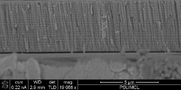
A structurally right-handed chiral STF was deposited on a pre-cleaned microscope glass slide (82027-788, VWR, Radnor, PA, USA) in a low-pressure chamber (Torr International, New Windsor, NY, USA) as follows. Two grams of powdered zinc selenide (Alfa Aesar, Ward Hill, MA, USA) were loaded into a tungsten boat (S6-.005W, R. D. Mathis, Long Beach, CA, USA) which was secured as the heating element in an electrical heater located inside the low-pressure chamber. The glass slide and a silicon wafer were affixed side by side to a rotatable planar platform about 15 cm above the boat. A quartz crystal monitor was mounted close to the platform to help control the deposition rate. The platform was oriented so that a collimated vapor flux of zinc selenide would be directed during deposition at deg with respect to the plane of the platform. The chamber was closed and pumped down to a base pressure of Torr. Then a -A current was passed through the tungsten boat. The serial bideposition technique [7] was implemented while maintaining the deposition rate at nm s-1. A 6-periods-thick chiral STF was grown. The procedure was repeated without removing the glass slide and the silicon wafer but after replenishing the boat with zinc selenide so that the chiral STF finally had 12 periods along the thickness direction.
Cross-sectional images of the 12-periods-thick chiral STF grown on the silicon wafer were acquired on a scanning electron microscope (FEI Nova NanoSEM 630, Hillsboro, OR, USA). Structural chirality is clearly evident in the representative image shown in Fig. 1. As the thickness m, the period of the chiral STF is nm.
A custom computer-controlled variable-angle spectroscopic system was used to measure the circular reflectances (, , , and ) of the chiral STF on the glass slide as functions of and . The first subscript in indicates the Left-circular polarization (LCP) state of the reflected light and the second subscript indicates the Right-circular polarization (RCP) state of the incident light, and similarly for the other three circular reflectances. Co-polarized reflectances have both subscripts identical, but cross-polarized reflectances do not.
Light from a halogen light source (HL-2000, Ocean Optics, Dunedin, FL, USA) was passed first through a Glan–Taylor linear polarizer (GT10, ThorLabs, Newton, NJ, USA) positioned inside a lens tube mount (SM1PM10, ThorLabs) inserted in a rotation mount (PRM1Z8, ThorLabs) and then through a Fresnel rhomb (LMR1, ThorLabs), before impinging on the chiral STF. The polarizer was set so that the light incident on the chiral STF possessed either the RCP or the LCP state. The chiral STF was mounted on a rotatable stage to change the angle as desired. The light specularly reflected by the chiral STF traveled through a Fresnel rhomb and a Glan–Taylor linear polarizer to a CCD spectrometer (HRS-BD1-025, Mightex Systems, Pleasanton, CA) to measure the intensity. The second polarizer was set so that the light incident on the CCD spectrometer possessed either the RCP or the LCP state. The reflected intensity was divided by the previously measured incident intensity to obtain the circular reflectance. We measured all four circular reflectances, first of the chiral STF on the glass slide alone and then of the chiral STF on the glass slide backed by a silver mirror (PFSQ10-03-P01, Thorlabs).
3 Results and discussion
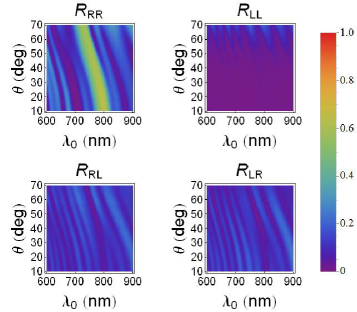
Measured spectrums of the four circular reflectances of the structurally right-handed chiral STF deposited on the glass slide are shown in Fig. 2 for . The circular Bragg regime is clearly manifested in the spectrum of as a high-intensity ridge that blue shifts as increases, no similar feature being evident in the spectrum of [4, 5, 8, 9]. Indeed, in this regime, which has center wavelength nm and full-width-at-half-maximum bandwidth nm when . The center wavelength blue shifts to nm as increases to , as determined from the experimental -data using the scheme described elsewhere [10]. Even though the cross-polarized circular reflectances and are very small, low-intensity troughs identifying the circular Bragg regime are weakly evident in the spectrums of these two reflectances. Although the reflectances could not be measured for normal incidence, conclusions on the center wavelength and the bandwidth of the circular Bragg regime drawn from deg can be easily extended to [10].
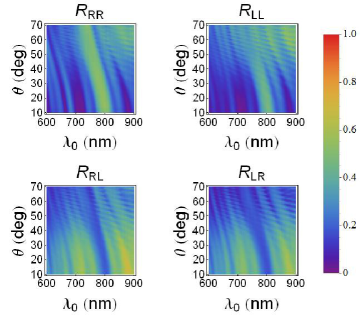
Measured spectrums of the four circular reflectances of the zinc-selenide chiral STF backed by a silver mirror are shown in Fig. 3 for . The circular Bragg regime is evident in the spectrum of as a high-intensity ridge that blue shifts with increasing —similarly to the high-intensity ridge in the spectrum of in Fig. 2. The center wavelength blue shifts from nm to nm as increases from to , also as determined from the experimental -data [10].
The circular Bragg regime is evident in Fig. 3 also as a high-intensity ridge in the spectrum of . Although still exceeds , the difference is considerably smaller than in Fig. 2. Furthermore, low-intensity troughs in the spectrums of and in Fig. 3 are additional footprints of the circular Bragg phenomenon, these troughs being far more prominent than in Fig. 2.
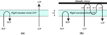
The differences between the spectrums shown in Figs. 2 and 3 can be explained as follows. Coupled-mode theory shows that the structurally right-handed chiral STF functions as a Bragg reflector when normally incident light has the RCP state [11, 12]; furthermore, time-domain simulations indicate that the reflection takes place through a large region of the chiral STF close to its entry pupil [13], which is the reason for to be sufficiently large in comparison to the period of an SCM for a significant manifestation of the circular Bragg phenomenon [4]. For incident light of the LCP state, the right-handed chiral STF functions simply as a homogeneous material, so that reflection is low and transmission is high (if dissipation is weak). Hence, . Cross-polarized reflectances and transmittances are usually small, and can be further decreased by the use of impedance-matching layers on both faces of the chiral STF. The simple cartoon in Fig. 4(a) depicts the chief features of the circular Bragg phenomenon, after ignoring the cross-polarized remittances and with the assumption that is sufficiently large. As increases, a blue shift of the circular Bragg regime occurs [10], but the simple cartoon in Fig. 4(a) remains valid to a great extent. The foregoing characteristics are evident in the spectrums presented in Fig. 2. The circular-polarization selectivity vanishes at very high values of [4], but those values of could not be covered in our experimental setup.
Over the spectral regime nm nm and for unpolarized light, the silver mirror used by us has a reflectance of at least for and for , according to the manufacturer. Therefore, in order to explain the characteristics of the circular Bragg phenomenon in Fig. 3, it is safe to assume that the silver mirror is a perfect reflector. Furthermore, the silver mirror reverses the handedness of the reflected light in relation to that of the incident circularly polarized light.
A small air gap exists between the back face of the glass slide and the silver mirror. As shown in Fig. 4(b), RCP light incident normally on the mirror-backed structurally right-handed chiral STF would be substantially reflected from within the chiral STF, provided that is sufficiently large and the wavelength lies in the circular Bragg regime; very little light would be incident on and be reflected by the mirror. A substantial fraction of LCP light incident normally on the same structure would reach the air gap, be incident on the silver mirror, and would undergo three reflections before traversing the chiral STF as RCP light—as shown also in Fig. 4(b). Since incident RCP light would travel through the chiral STF for a shorter distance than incident LCP light would, the latter would be absorbed more than the former, leading to exceeding , but the difference between the two co-polarized reflectances would not be as stark as when the mirror were to be removed.
Although cross-polarized remittances and small co-polarized remittances were ignored, the foregoing simple explanation suffices to understand the effect of the backing mirror. The blue shift of the circular Bragg regime with increasing would not be disturbed by the mirror. Outside the circular Bragg regime, and would be expected to be enhanced by the reversal of the circular polarization state by the mirror, a feature that is clearly identifiable on comparing Figs. 2 and 3. That enhancement also intensifies the footprints of the circular Bragg phenomenon in the spectrums of and in Fig. 3 relative to their counterparts in Fig. 2.
To conclude, we have experimentally established that the signature of the circular Bragg phenomenon is clearly evident in the spectrums of all four circular reflectances of a modestly dissipative chiral STF backed by a metallic reflector. When the mirror is absent, strong evidence of the circular Bragg phenomenon exists only in the spectrum of the co-polarized and co-handed reflectance (i.e., in Fig. 2).
Acknowledgments
S.E. thanks the Turkish Ministry of National Education for financial support of her graduate studies. S.E.S. and A.L. are grateful to the Charles Godfrey Binder Endowment at the Pennsylvania State University for financial support.
References
- [1] J. L. Fergason, “Cholesteric structure—I. Optical properties,” Mol. Cryst. 1(2), 293–307 (1966).
- [2] S. Chandrasekhar, Liquid Crystals, 2nd ed., Cambridge University Press, Cambridge, United Kingdom (1992).
- [3] P. G. de Gennes and J. A. Prost, The Physics of Liquid Crystals, 2nd ed., Clarendon Press, Oxford, United Kingdom (1993).
- [4] A. Lakhtakia and R. Messier, Sculptured Thin Films: Nanoengineered Morphology and Optics, SPIE Press, Bellingham, WA, USA (2005).
- [5] M. Faryad and A. Lakhtakia, “The circular Bragg phenomenon,” Adv. Opt. Photon. 6(2), 225–292 (2014).
- [6] S. D. Jacobs (Ed.), Selected Papers on Liquid Crystals for Optics, SPIE Optical Engineering Press, Bellingham, WA, USA (1992).
- [7] I. Hodgkinson, Q.-h. Wu, B. Knight, A. Lakhtakia, and K. Robbie, “Vacuum deposition of chiral sculptured thin films with high optical activity,” Appl. Opt. 39(4), 642–649 (2000).
- [8] H. Takezoe, Y. Ouchi, M. Hara, A. Fukuda, and E. Kuze, “Experimental studies on reflection spectra in monodomain cholesteric liquid crystal cells: total reflection, subsidiary oscillation and its beat or swell structure,” Jpn. J. Appl. Phys. 22(1), 1080–1091 (1983).
- [9] W. D. St. John et al., W. D. St. John, W. J. Fritz, Z. J. Lu, and D.-K. Yang, “Bragg reflection from cholesteric liquid crystals,” Phys. Rev. E 51(2), 1191–1198 (1995).
- [10] S. Erten, A. Lakhtakia, and G. D. Barber, “Experimental investigation of circular Bragg phenomenon for oblique incidence,” J. Opt. Soc. Am. A 32(5), 764–770 (2015).
- [11] V. A. Belyakov, V. E. Dmitrienko, and V. P. Orlov, “Optics of cholesteric liquid crystals,” Sov. Phys. Usp. 22(2), 63–88 (1979).
- [12] M. W. McCall, “Simplified theory of axial propagation through structurally chiral media,” J. Opt.: Pure Appl. Opt. 11(7), 074006 (2009).
- [13] J. B. Geddes III and A. Lakhtakia, “Numerical investigation of reflection, refraction, and diffraction of pulsed optical beams by chiral sculptured thin films,” Opt. Commun. 252(4-6), 307–320 (2005).