TPC-like readout for thermal neutron detection using a GEM-detector
Abstract
Spatial resolution of less than 200 m is challenging for thermal neutron detection. A novel readout scheme based on the time-projection-chamber (TPC) concept is used in a gaseous electron multiplier (GEM) detector [1]. Thermal neutrons are captured in a single 2 m thick Boron-10 converter cathode and secondary Helium and Lithium ions are produced with a combined energy of 2.8 MeV. These ions have sufficient energy to form straight tracks of several mm length. With a time resolving 2-dimensional readout of 400 m pitch in both directions, based on APV25 chips, the ions are tracked and their respective origin in the cathode converter foil is reconstructed. Using an Ar-CO2 93:7% gas mixture, a resolution of 100 m (FWHM 235 m) has been observed with a triple GEM-detector setup at the Garching neutron source (FRMII) for neutrons of 4.7 Å.
keywords:
Gas Detectors1 Introduction
Thermal neutron detection with spatial resolution around or below 0.2 mm will become mandatory for modern thermal neutron crystallography or fast imaging detectors [2].
Gaseous micro-pattern detectors like GEM (gaseous electron multiplier) or Micromegas have proven to reach spatial resolutions well below 100 m [3], depending on the fineness of their segmentation. Here a self calibrating TPC-like analysis for this kind of detector is presented with a GEM-detector.
2 TPC-like Analysis of Ion Tracks
A triple GEM-detector with segmented 2D-readout of 0.4 mm pitch was used in combination with a 10B converter cathode to detect thermal neutrons. Thermal neutron capture in 10B has a high cross section and produces a 7Li and a 4He ion back-to-back with a combined energy of 2.8 MeV.
The heavy He or Li ion create a straight line of ionized electrons in the drift-volume of a micro-pattern detector. The full track information can be reconstructed from the electron drift time measured as a function of the responding readout segments. This allows for reconstruction of the neutron interaction point in the converter cathode.
The APV front-end-electronics samples the signal on every strip in steps of 25 ns. With typical rise times of 150 ns the beginning of a signal, and thus the drift time of the respective electrons, can be determined with a fit to the rise of the charge distributions.
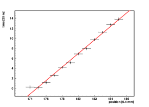
From a fit to the starting times as a function of hit strips the inclination angle of the track can be reconstructed.
3 Determination of spatial resolution
As conversion cathode a 2 m layer of 10B evaporated on an aluminum supporting sheet has been used. It was mounted to a triple GEM detector with two-dimensional strip readout, based on crossed strips with a pitch of 400 m in both directions. The readout anode was delivered by CERN. X and Y directions are covered by 256 strips each with a copper strip width of 80 m for the upper layer and 320 m for the lower layer. All the insulator material but the direct insulation between X and Y copper strips have been etched off, such that the different copper width guarantees similar pulse-height in both planes. The readout is based on APV-25 front-end boards [4] and the SRS data acquisition system [5] and was triggered by the signal on the lower side of the last GEM-foil, which is in principle the inverted signal of the readout plane. The drift gas, Ar-CO2 of 93:7 Vol.% at atmospheric pressure, defines in combination with the thickness of the absorber the maximum range of the 4He ions to 12 mm. The width of the drift gap of 6 mm was chosen to decrease the impact of the Bragg-peak in the track reconstruction and to assure that only tracks with large inclination angle stop in the active volume. The distances between GEM-foils and the distance between last GEM-foil and the readout anode was 2 mm each. For optimized spatial resolution the drift velocity of the electrons was chosen quite low to 11 m/ns, by adapting the electric field in the drift region to the time resolution of the APV25 chips.
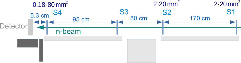
Neutrons of 4.7 Å are available at the Garching FRMII research reactor at the TREFF beam line. The beam was collimated by a system of four apertures, see figure 2. The collimation was done by the collimators 1, 2 and 4 and a possible beam halo was cut by collimator 3. The beam was formed to a slit of 180 m width and 65 mm height, defined by the collimators on the last aperture, which lead to a maximum width of the beam spot on the converter cathode of 250 m with only 0.32 mrad divergence. To determine the neutron profile on the conversion layer the hit distribution has been approximated by a boxcar function. The convolution with the Gaussian-distribution describing the spatial detector resolution allows then to simulate the measured distribution. This leads to a double error-function of the form:
| (1) |
denotes a normalization factor, is the half width of the slit, is the center of the slit and is the standard deviation of the Gaussian, which represents the detector-resolution.
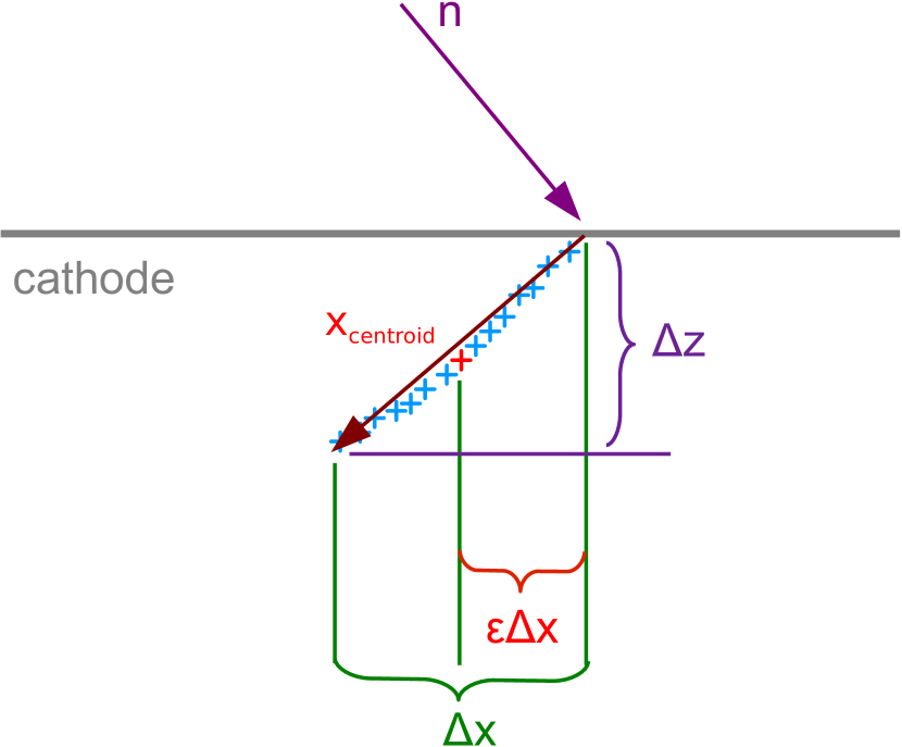
In a standard analysis the neutron position would be determined by the center of the charge distribution for every track in the readout plane. The error in position resolution is therefore limited by the inclination angle and the length of the track of the secondary ion, see figure 3. The resolution achievable by this method is a FWHM of 3.4 0.1 mm.
The resolution can be improved by determining the starting point of the secondary ion track and thus the point of conversion in the cathode.
With a single GEM-detector spatial resolution of below 470 m could already be achieved by determination of the last strip, which was hit in a track([6]). In a triple GEM-setup the spread of the charge cloud by diffusion towards the anode is quite significant. This can be overcome by fully tracking the ions in the drift volume.
The method would work best if all ions would transverse the complete drift region and if the correlation between responding readout strips and ion track would be precise. Certainly, ions with large inclination angles stop within the 6 mm wide drift region. The systematic effects: electron diffusion and capacitive coupling of neighboring readout strips, lead to an overestimation of the length of the track on both ends for both traversing and stopping ions. Therefore, the TPC-like reconstruction is dependent on the track length, the inclination angle, and the non-homogeneous the charge distribution in the track, the skewness. Skewness and track length are dependent on the particle type as well.
In the following the dependencies of the reconstruction on the track length, and the skewness of the charge distribution in the track will be discussed. These corrections are performed by linear fits to internal detector correlations see figure 3.
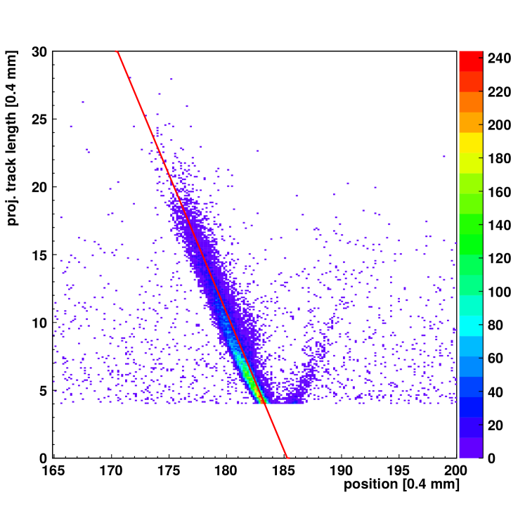
Figure 5 shows a clear correlation between the projected track length in one readout direction of a track and the reconstructed position. The length of the track is determined from a Gaussian fit to the charge distribution on all responding strips individually in X and Y direction. The dependence of the centroid position on the projected track length was determined by linear fit and the position was corrected depending on the projected track length.
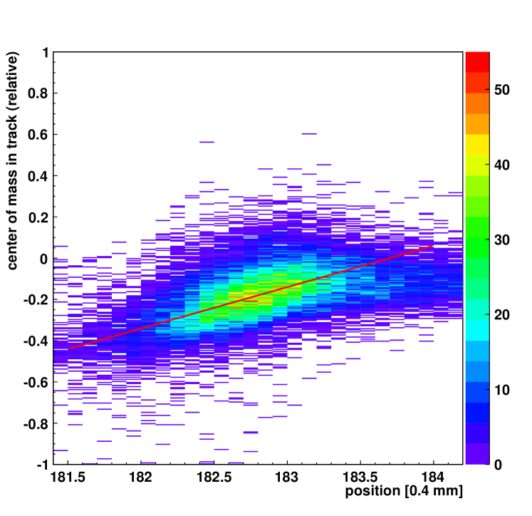
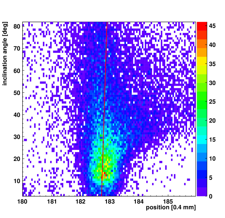
After application of this correction the dependence of the reconstructed position on the skewness of the charge distribution is shown in figure 6. The linear fit gives the parameters for the correction in a second step and in the last step the fit to the reconstructed angle of the track as a function of reconstructed position is investigated, as shown in figure 7.
Since there are dependencies of all these measurement parameters it is not advantageous to correct them iteratively in a calibration one after the other.
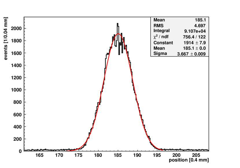
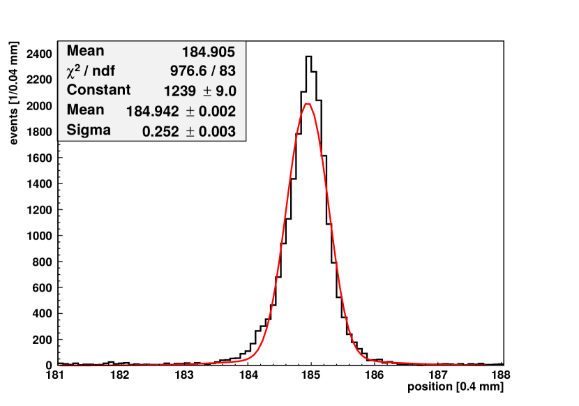
The result of this calibration is shown in figure 8, where the projection of the strip in the X-direction is shown and the resolution is determined by a fit of equation 1. A spatial resolution of (235 25) m FWHM ((100 15) m) is achieved.
4 Conclusion
Using TPC analysis the inclination angle of the track is determined, which defines the direction of the track. As origin the centroid of the tracks was determined and its dependence on the track length, inclination angle, and the skewness of the charge distribution in the track is examined. The iteration of calibration factors determined from linear fits to the reconstructed position in dependence to the mentioned track parameters were adapted to compensate for these. Altogether this corrections in addition to a cut on the minimal track length of 3.5 strips in both directions led to a gaussian distribution with an improved resolution of (23525) m FWHM ( 10015 m) in comparison to a standard centroid determination with a resolution of 3.4 mm.
This procedure produces implicitly correction factors that have been so far obtained in MIP tracking experiments by dedicated calibration runs with known incidence angle of the particle beam.
Acknowledgments
This work is based upon experiments performed at the TREFF instrument operated by FRMII at the Heinz Maier-Leibnitz Zentrum (MLZ), Garching, Germany.
The authors thank H. Takahashi (University of Tokyo) for providing of the 10B cathode.
References
- [1] F. Sauli, GEM: A new concept for electron amplification in gas detectors, Nucl. Instrum. Meth. A386 (1997) 531–534.
- [2] O. Kirstein, et al., Neutron Position Sensitive Detectors for the ESS, arXiv:1411.6194v1 [physics.ins-det] 23 Nov 2014.
- [3] J. Bortfeldt, et al.,High-resolution Micromegas telescope for pion- and muon-tracking,Nucl. Instrum. Meth. A718 (2013) 406–408.
- [4] M. French, et al.,Design and Results from the APV25, a Deep Submicron CMOS Front-End Chip for the CMS Tracker , Nuclear Instruments and Methods in Physics Research A 466 (2001) 359-365.
- [5] S. Martoiu, et al, Development of the scalable readout system for micro-pattern gas detectors and other applications , Journal of Instrumentation 8 (2013) C0301.
- [6] D. Pfeiffer, et al., The TPC Method: Improving the Position Resolution of Neutron Detectors Based on MPGDs , JINST 10 (2015) P04004.