Polariton waveguides from a quantum dot chain in a nanowire photonic crystal:
an architecture for quantum information science and waveguide QED
Abstract
We introduce a polariton-waveguide structure, comprised of a nanowire-based photonic crystal waveguide with a quantum dot embedded in each unit cell. Using realistic designs and parameters, we derive and calculate the fundamental electromagnetic properties of these polariton waveguides, with an emphasis on the photon Green function and local optical density of states (LDOS). Both infinite and finite-size waveguides are considered, where the latter’s properties are calculated using a Dyson equation approach without any approximations. We demonstrate dramatic increases, and rich fundamental control, of the LDOS due to strong light-matter interactions in each unit cell through periodic quantum dot interactions. Consequently, these structures allow the exploration of new regimes of waveguide quantum electrodynamics. As an example application, we consider the coupling of an external target quantum dot with a finite-sized polariton waveguide, and show that the single quantum dot strong coupling regime is easily accessible, even for modest dipole strengths.
pacs:
42.50.Ct, 42.50.Nn, 78.67.Hc, 78.67.QaThe design of nanoscale solid state devices to control light-matter interactions is highly desirable, both for applications in quantum information science Yao et al. (2009a) and to explore novel regimes of quantum electrodynamics (QED) Fink et al. (2008); Greentree et al. (2006). Photonic crystals (PCs) with embedded quantum dots (QDs) have had much success in this regard by modifying the LDOS John and Wang (1990); Hennessy et al. (2007); Gao et al. (2013); Bose et al. (2012), although they have been hindered by fabrication issues including surface roughness Hughes et al. (2005); Patterson et al. (2009); Fussell et al. (2008) and limited control of the QD properties BaHoang2012. Arrays of nanowires (NWs) grown through a molecular beam epitaxy (MBE) technique Dubrovskii2009; Joyce2011 have been proposed as an alternative PC platform to help mitigate these issues Angelatos2014; Angelatos2015, with the potential to contain identical or very similar QDs inside each NW of a given radius Makhonin2013; Diedenhofen2011. This opens the idea of NW PC waveguides where each waveguide channel NW contains an identical QD embedded in its center. Coupled dipole chains in free space have interesting collective properties, and can act as subwavelength waveguides Citrin2004; implementing such chains in PC waveguides could result in new physical behavior or improved performance. Metamaterials, comprised of multiple elements that are engineered to have unique and useful properties, have been used to produce exotic waveguides with a dramatically different LDOS than simple dielectric structures, e.g., manifesting in large spontaneous emission rate enhancements Li2009; Yao2009meta for dipole emitters, even with material losses. Plasmonic polariton waveguide structures Christ2003 and metal nanoparticle chains coupled to traditional waveguides Fevrier2012 have demonstrated chain-mediated coupling between plasmonic and photonic excitations leading to an anti-crossing in the band structure. This polariton anti-crossing is also observed with quantum wells in 1D distributed Bragg reflector waveguides Yablonskii2001. All these structures essentially lead to normal mode splitting.
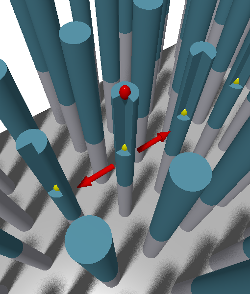
Inspired by the metamaterial concept and advances in NW growth techniques, the inclusion of a QD chain in a PC waveguide can similarly reshape and greatly enhance the system LDOS and result in drastically different properties and behavior, but without the large metallic losses of plasmonic metamaterials. In this Letter, we introduce and explore the optical properties of a nanophotonics system comprised of a PC waveguide with an embedded QD in each unit cell, which we describe as a “polariton waveguide” because its excitations are mixed light-matter states due to the collective coupling of the QDs with the waveguide Bloch mode. Figure 1(a) shows a schematic of our proposed structure. To elucidate the underlying physics of these systems, we derive the photon Green function (GF) of both infinite and finite-sized systems polariton waveguides, and explore their coupling with a single external “target” QD, which is found to be in the strong coupling regime. This achievement of strong coupling between a single isolated emitter and a waveguide mode, to the best of our knowledge first reported here, allows for the creation of devices relying on quantum cavity physics, such as photon blockades and single photon switches Greentree et al. (2006); Bose et al. (2012), with reliable input/output coupling on chip. Our polariton waveguide architecture can also be adapted for other systems such as circuit QED Fink et al. (2008).
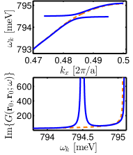
Our proposed structure exploits the elevated NW PC waveguide design of Ref. Angelatos2014, where a PC waveguide is formed from an organized array of GaAs NWs extended from an AlO substrate Tokushima2004, with the waveguide channel introduced by reducing the radius of a row of NWs from to along . Importantly, this structure is based on current fabrication techniques and properties are determined through full 3D calculations including radiative coupling effects. The PC waveguide with lattice constant m contains a single vertically-polarized below-light-line waveguide band with a mode edge near the telecom wavelength of m (ranging from meV). Light is confined to the upper GaAs portion of the NWs (height ), while the AlO layer separates them from the substrate and an array width of is sufficient to prevent in-plane losses. As this waveguide band approaches the mode edge it flattens due to symmetry and the group velocity goes to zero, causing the LDOS to diverge as seen in Fig. 1LABEL:sub@Gcomp, an effect that is inevitably spoiled by disorder-induced losses in real systems Hughes et al. (2005). To form the polariton waveguide of Fig. 1LABEL:sub@scheme, we embed a QD in the center of the GaAs layer of each waveguide NW at , where is an integer. We take the embedded QDs to have a Lorenzian polarizability , with a dipole moment D (e-nm) and polarization decay rate eV (including both non-radiative decay and coupling into non-waveguide modes); these are similar to experimental parameters for InAs QDs at 4 K Weiler2012. The QD exciton line is taken to be meV, which is in the moderately-slow-light regime of the waveguide band resulting in a group velocity and (relative LDOS enhancement, ). Throughout this work, we connect to the GF , which describes the system electric-field response at to a point source at (fully including all light scattering events), and whose imaginary and real components at equal space points are directly proportional to the system LDOS (and emitter spontaneous emission rate), and Lamb shift, respectively Yao et al. (2009a); Angelatos2015. These GFs are projected along the relevant component for vertically polarized QDs: and given in units of the imaginary part of free-space GF Novotny2006. When we consider the addition of an external target QD to the waveguide, this will be embedded on the top of waveguide NW at position , where indexes the unit cell, as seen in Fig. 1LABEL:sub@scheme, both for fabrication purposes and because this is where the antinode of the waveguide mode resides.
We first consider an infinite embedded QD array to help explain these structures’ underlying physics, exploiting Bloch’s theorem and treating the QDs as a perturbation to each PC unit cell , which shifts the waveguide resonance for a given to . We obtain from perturbation theory, Mahmoodian2009; Patterson2010; Angelatos2015th, where is the unit cell volume and is the waveguide unit-cell function, normalized through , with corresponding waveguide mode where the waveguide length. The waveguide band is split by the QD–Bloch-mode interaction, resulting in a pair of complex eigenfrequencies at each , with and . The QD–unit-cell coupling parameter gives the strength of the light-matter interaction leading to anti-crossing and is the continuum form of , the single mode quantum optical coupling rate. This modified band structure is compared with that of the original PC in Fig. 1LABEL:sub@Gcomp, where the strong mode splitting ( ) flattens the dispersion as and losses remain low: . The inclusion of the QD array has caused the waveguide band to split, corresponding to a mixed light-matter excitation: the polariton waveguide.
The above approach was also applied to the waveguide Bloch modes: away from where perturbation theory naturally breaks down we find only the waveguide Bloch mode contribution is significant and , and we only show results for frequencies where perturbation theory still holds. We write the GF of this infinite polariton waveguide as a sum over these waveguide Bloch modes, , and converting this sum to an integral in the complex plane Angelatos2015th, we arrive at an analytic expression similar in form to that for a regular PC waveguide Rao2007theory; Yao et al. (2009a):
| (1) |
but with , where is the polariton waveguide group velocity and . We emphasize that both and are found from the polariton waveguide relationship, which differs greatly from that of the original PC near due to the polariton splitting. This was derived assuming , which remains valid until , where . The effect of the QD array, demonstrated in Fig. 1LABEL:sub@Gcomp, is thus to produce large and tunable LDOS enhancements near resonance by flattening the band structure; as one moves away from the original PC waveguide GF is quickly recovered. At the above minimum detuning, these polariton waveguides yield —a dramatic rate enhancement and indicative that these structures should enter the strong coupling regime of QED, even at the single quantum level.
We next consider polariton waveguides with a finite number of embedded QDs, more representative of real systems. We can no longer exploit Bloch’s theorem, but instead include QDs iteratively in the system GF via an exact Dyson equation approach. Denoting the background PC waveguide Green function as and starting with unit cell , we introduce a QD at , calculate the resultant Green function including scattering from this QD, and then use this as the background Green function to introduce a QD in the subsequent unit cell. From the Dyson equation, QD can be included self-consistently in the system GF through Kristensen2011 This was done numerically using the same system as for the infinite case (i.e. identical PC waveguide and QDs) for QD chains of increasing length, .
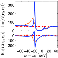
Figure 2 shows , corresponding to a chain sufficiently long to produce substantial LDOS enhancements and begin to recover the infinite chain result, while still demonstrating important finite-size effects. We chose to emphasize the position on top of the central NW of the QD array (where a target QD will be later embedded) because constructive interference from repeated QD scattering maximizes the polariton effects. The addition of a single QD introduces a dip in at , however with increasing the build up of off-resonant enhancement from QD scattering leads to the formation of a strong resonance in which exceeds for . This resonance is red-shifted from , with a peak and FWHM eV at eV for the 101 QD case. As more QDs are added, this polariton peak grows, narrows, and blue-shifts towards while additional weaker red-shifted resonances begin to appear. Above , resonances also form which grow and become more numerous with increasing , indicating that they arise from QD chain Fabry-Pérot (FP) modes. The higher two FP modes for the structure are at eV and eV. Away from , converges to the PC waveguide GF, as was seen for the infinite case. The large number of resonances in these waveguides also produce a richly varying which remains substantial over a broad frequency region, particularly for larger .
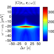
The above results were also found to be robust to disorder in embedded QD position and dipole moment; e.g., random variations of up to nm and 3 D reduced the strength of the primary peak slightly () and introduced a frequency shift of eV, but the underlying system behavior remained unchanged. Similarly, these findings were also verified to hold for eV, with the dip extending deeper and resonances initially appearing at lower and closer to as is reduced. Figure 2LABEL:sub@Gprop101 shows the propagator , which is proportional to the coupling strength between the target QD location and various points in the structure, and far greater coupling rates are found than for a bare ideal PC waveguide. For instance, and are found for , and one can produce effectively any arbitrary combination of and through careful choice of separation and frequency. This GF reshaping persists even past the mode edge of the polariton waveguide: once one is outside of the QD chain, experiences only a phase shift of as and are varied and has a peak of at (eV), more than double the bare PC waveguide result: . Notably these finite-sized GFs are derived without any approximations, and reproduce the physics of the infinite structure, namely strong light-matter interactions resulting in dramatic enhancements in the system LDOS.
We now consider an important quantum optical application of these polariton waveguides, studying the interaction of a single external QD at of the polariton waveguide. The LDOS enhancements, specifically the polariton peak at , are possibly sufficient to strongly couple the waveguide to a realistic QD. We follow a first principals quantization procedure appropriate for lossy inhomogeneous systems Suttorp2004 such as these polariton waveguides. The system Hamiltonian in the dipole approximation, consisting of a single target QD interacting with the electromagnetic environment of the polariton waveguide, is given by where the QD is a two-level atom (TLA) with exciton frequency and transition dipole moment ; is the bosonic field annihilation operator associated with the field frequency which generates the electric-field operator via Suttorp2004. We Laplace transform the resulting operator Heisenberg equations of motion to construct the spontaneous emission spectrum at detector position : , which yields
| (2) |
where we have assumed an initially excited QD in vacuum. The self-energy is , and is the polarization decay rate of the target TLA due to interactions with the environment (i.e., anything other than the LDOS given by the polariton waveguide GF). The spectrum depends not only on the GF at TLA position but also on the propagator to the detector . When we present spectra below, we show both and , where is calculated from Eq. (2) by replacing the propagator in the numerator with . This is done because is often distorted by the rich spectral features of the GFs of these waveguide structures (see Fig. 2b). The bare spectrum thus more cleanly shows the system energy levels and dynamics of the target QD.
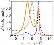
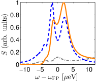
We assume a -aligned target QD with a polarization decay rate eV and calculate spectra for target QD dipole moments of , , and D, encompassing the range of QDs which could feasibly be coupled to the polariton waveguide. For a simple Lorentzian LDOS, the resultant system dynamics can be approximated with the Jaynes-Cummings (JC) Hamiltonian, where the interaction of a single photonic mode and TLA leads to an anti-crossing as they approach resonance (splitting of on resonance); near we define an effective coupling constant Angelatos2015th. The three target dipole moments produce of 1.24, 3.72, and eV, respectively, which meet the criteria for strongly coupling with the resonance: Meystre1999. We assign a detector position , which is outside the polariton waveguide portion of the structure to reduce the filtering of the detected spectrum, while in the same position in the unit cell as the QD to maximize coupling. The emitted and detected spectra and at for the D QD is shown in Fig. 3LABEL:sub@scspecres. Remarkably, substantial splitting is seen in both and despite the modest choice of and peak locations of eV and eV agree well with the JC Hamiltonian when the Lamb shift is included; however we stress that the widths and weighting of the spectral peaks, as well as propagation effects and polarization decay, are only captured through the formalism leading to Eq. 2; in particular, the reduced height of the peak is a result of the unique shape of near producing a large positive Lamb shift. The importance of propagation effects can clearly be seen by comparing and , where the depletion above reduces the height of the peak. In Fig. 3LABEL:sub@scspecfpb we show the spontaneous emission spectra at for D, where the QD–polariton-waveguide coupling is sufficiently strong that significant exchange occurs with both the and modes for . This results in a triplet forming in , with peaks at eV, eV, and eV; the splitting is substantially stronger than so these peaks are clearly seen at the detector position as well.
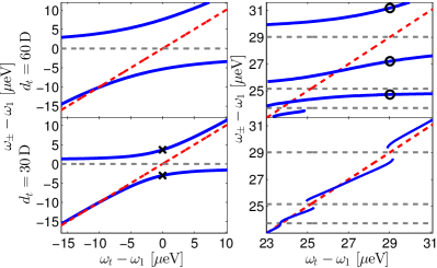
Finally, to demonstrate that the features in the above spontaneous emission spectra are a consequence of the strong coupling regime, the clearly resolvable peaks of as is brought to resonance with are shown in Fig. 4 for a target QD with and D. The left plots depict anti-crossing with the primary resonance at , while the peaks as is swept through the FP region are shown on the right and markers denote the peaks of Fig. 3. Remarkably for a waveguide system, all three QDs ( D is not shown) demonstrate a clear anti-crossing as they approach , conclusive evidence that they are strongly coupled to the polariton-waveguide despite the complicated nature of this system. While similar strong coupling behavior has been theoretically predicted for coupled-cavity PC waveguides Fussell2007, a later study showed this was inevitably spoiled by disorder Fussell et al. (2008). Strong coupling has recently been observed with Anderson-localized cavities in disordered PC waveguides Gao et al. (2013), although this is fundamentally different from strong coupling with a propagating waveguide mode as reported here. It is also impressive that our predicted splitting is seen even for the D target QD, which is much weaker than that used in other studies. Of further interest is the system behavior in the FP region of the polarition waveguide, where the unusual shape of the system LDOS leads to multiple anti-crossings which are poorly described by a JC Hamiltonian. The interaction of the FP modes with the D target QD is particularly striking: up to four energy levels are seen for a given and the multi-mode nature of the QD-polariton waveguide has flattened these anti-crossing lines.
In conclusion, we have proposed a new nano-engineered metamaterial system, a polaritonic waveguide, consisting of a PC waveguide with periodic embedded QDs. We developed two separate approaches to describe the physics of this system, studying both infinite and finite polariton waveguides and demonstrating that in both instances strong light-matter interactions lead to rich and dramatic LDOS enhancements which are robust to disorder and without the losses typically associated with metallic metamaterials. We then considered the interaction of a finite-size structure with an external QD and we showed that these LDOS enhancements can be exploited to strongly couple with a single external emitter and produce interesting spectral features clearly visible in the externally detected spectrum. These structures could thus be used to design complex devices for quantum information and explore new regimes of open system waveguide QED.
This work was supported by the Natural Sciences and Engineering Research Council of Canada and Queen’s University.
References
- Yao et al. (2009a) P. Yao, V. S. C. Manga Rao, and S. Hughes, Laser Photon. Rev. 4, 499 (2009a).
- Fink et al. (2008) J. M. Fink, M. Göppl, M. Baur, R. Bianchetti, P. J. Leek, Blais, and A. Wallraff, Nature 454, 315 (2008), arXiv:0902.1827 .
- Greentree et al. (2006) A. D. Greentree, C. Tahan, J. H. Cole, and L. C. L. Hollenberg, Nat. Phys. 2, 856 (2006).
- John and Wang (1990) S. John and J. Wang, Physical Review Letters 64, 2418 (1990).
- Hennessy et al. (2007) K. Hennessy, A. Badolato, M. Winger, D. Gerace, M. Atatüre, S. Gulde, S. Fält, E. L. Hu, and A. Imamoğlu, Nature 445, 896 (2007).
- Gao et al. (2013) J. Gao, S. Combrie, B. Liang, P. Schmitteckert, G. Lehoucq, S. Xavier, X. Xu, K. Busch, D. L. Huffaker, A. De Rossi, and C. W. Wong, Sci. Rep. 3, 1994 (2013).
- Bose et al. (2012) R. Bose, D. Sridharan, H. Kim, G. S. Solomon, and E. Waks, Phys. Rev. Lett. 108, 227402 (2012).
- Hughes et al. (2005) S. Hughes, L. Ramunno, J. F. Young, and J. E. Sipe, Phys. Rev. Lett. 94, 033903 (2005).
- Patterson et al. (2009) M. Patterson, S. Hughes, S. Combrié, N.-V.-Q. Tran, A. De Rossi, R. Gabet, and Y. Jaouën, Phys. Rev. Lett. 102, 253903 (2009).
- Fussell et al. (2008) D. P. Fussell, S. Hughes, and M. M. Dignam, Phys. Rev. B 78, 144201 (2008).