Space-Frequency Block Code for MIMO-OFDM Communication Systems with Reconfigurable Antennas

Vida Vakilian1, Jean-François Frigon1, and Sébastien Roy2 1 École Polytechnique de Montréal, Dept. of Electrical Engineering, Montréal, QC, H3T 1J4, Canada
{vida.vakilian, j-f.frigon}@polymtl.ca
2 Dept. of Elec. and Comp. Engineering, Université Sherbrooke Sherbrooke, QC, Canada
sebastien.roy13@usherbrooke.ca
Abstract

We propose a space-frequency (SF) block coding scheme for a multiple-input multiple-output (MIMO) orthogonal frequency-division multiplexing (OFDM) system using antennas with reconfigurable radiation patterns. In this system, each element of the antenna array at the transmitter side is assumed to be reconfigurable so that it can independently change the physical characteristics of its radiation pattern. The proposed block code is full rate and benefits from spatial, frequency, and reconfigurable radiation pattern state diversity over frequency-selective fading channels. We provide simulation results to demonstrate the performance of the proposed block coding technique and make comparisons with that of the previous SF coding schemes in MIMO-OFDM systems. The results indicate that the proposed code achieves higher diversity and coding gain compared to other available SF codes.

Index Terms:
Frequency-selective fading channels, multiple-input multiple-output-orthogonal frequency-division multiplexing (MIMO-OFDM) systems, space-frequency (SF) coding, reconfigurable antennas.

I Introduction

Reconfigurable antennas can be used in multiple-input multiple-output (MIMO) communication systems to increase the capacity and reliability of wireless links [1, 2, 3, 4, 5]. In a reconfigurable MIMO system, the characteristics of each antenna radiation pattern can be changed by placing switching devices such as Microelectromechanical Systems (MEMS), varactor diodes, or field-effect transistor (FET) within the antenna structure [6, 7, 8]. As a result, a system employing reconfigurable antennas is able to alter the propagation characteristics of the wireless channel into a form that leads to a better signal quality at the receiver. In fact, by using reconfigurable antennas and designing a proper code, we can achieve an additional diversity gain that can further improve the performance of wireless communication systems.

There are several works in the literature on designing efficient codes for reconfigurable MIMO systems in order to take advantage of the antenna reconfigurability. In [5], authors have proposed a MIMO system equipped with reconfigurable antennas at the receiver that can achieve a diversity order that equals to the product of the number of transmit antennas, the number of receive antennas and the number of reconfigurable states of the receive antennas. They have shown that this diversity gain is achievable only under certain channel propagation conditions and using an appropriate coding technique. Later on, in [9] authors extended the concept by using reconfigurable elements at both transmitter and receiver sides. In their work, they have introduced a state-switching transmission scheme, called space-time-state block coding (STS-BC), to further utilize the available diversity in the system over flat fading wireless channels. However, their coding scheme does not exploit the frequency diversity offered by the multipath propagation channels between each transmit and receive antenna pair.

To obtain frequency diversity in multipath environment, a space-frequency (SF) block code was first proposed by authors in [10], where they used the existing space-time (ST) coding concept and constructed the code in frequency domain. Later works [11, 12, 13, 14, 15, 16] also used similar strategies to develop SF codes for MIMO-OFDM systems. However, the resulting SF codes achieved only spatial diversity, and they were not able to obtain both spatial and frequency diversities. To address this problem, a subcarrier grouping method has been proposed in [17] to further enhance the diversity gain while reducing the receiver complexity. In [18], a repetition mapping technique has been proposed that obtains full-diversity in frequency-selective fading channels. Although their proposed technique achieves full-diversity order, it does not guarantee full coding rate. Subsequently, a block coding technique that offers full-diversity and full coding rate was derived [19, 20]. However, the SF codes proposed in the above studies and other similar works on the topic are not able to exploit the state diversity available in reconfigurable multiple antenna systems.

In this paper, we propose a coding scheme for reconfigurable MIMO-OFDM systems that achieves multiple diversity gains, including, space, frequency, and state. Basically, the proposed scheme consists of a code that is sent over transmit antennas, OFDM tones, and radiation states. In order to obtain state diversity, we configure each transmit antenna element to independently switch its radiation pattern to a direction that can be selected according to different optimization criteria, e.g., to minimize the correlation among different radiation states. We construct our proposed code based on the fundamental concept of rotated quasi-orthogonal space-time block codes (QOSTBC) [21, 22, 23]. By using the rotated QOSTBC, the proposed coding structure provides rate-one transmission (i.e., one symbol per frequency subcarrier per radiation state) and leads to a simpler Maximum Likelihood (ML) decoder. As the simulation results indicate, our proposed code outperforms the existing space-frequency codes substantially.

Refer to caption
Figure 1: Block diagram of a Reconfigurable MIMO-OFDM system employing reconfigurable antennas at the transmitter.

The rest of this paper is organized as follows. In Section II, we introduce the channel and system model for a reconfigurable MIMO-OFDM system. In Section III, we briefly discuss the code design for reconfigurable multiple antenna systems. Simulation results are presented in Section IV, and finally conclusions are drawn in Section V.

Notation: Throughout this paper, we use capital boldface letters for matrices, and lowercase boldface letters for vectors. ()Tsuperscript𝑇(\cdot)^{T} denotes transpose of a vector. 𝒞𝒞\mathcal{C} stands for the set of complex valued numbers. Operator diag(a1,a2,,an)diagsubscript𝑎1subscript𝑎2subscript𝑎𝑛\text{diag}(a_{1},a_{2},\cdots,a_{n}) represents a diagonal n×n𝑛𝑛n\times n matrix whose diagonal entries are a1,a2,,ansubscript𝑎1subscript𝑎2subscript𝑎𝑛a_{1},a_{2},\cdots,a_{n}. \lfloor\cdot\rfloor stands for the floor operation and 𝐈Nsubscript𝐈𝑁{\bf I}_{N} represents the N×N𝑁𝑁N\times N identity matrix. Operator col{}col\text{col}\{\cdot\} stacks up the matrices on top of each other.

II Channel and System Models for Reconfigurable MIMO-OFDM Systems
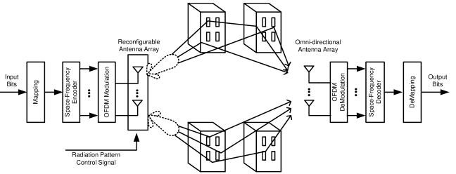
Consider a MIMO-OFDM system with Mtsubscript𝑀𝑡M_{t} reconfigurable elements at the transmitter where each of these elements is capable of electronically changing its radiation pattern and creating P𝑃P different radiation states as shown in Fig. 1. In this system, we assume the receiver antenna array consist of Mrsubscript𝑀𝑟M_{r} omni-directional elements with fixed radiation patterns. Moreover, we consider an Ncsubscript𝑁𝑐N_{c}-tone OFDM modulation and frequency-selective fading channels with L𝐿L independent propagation paths between each pair of transmit and receiver antenna in each radiation state. The channel gains are quasi-static over one OFDM symbol interval. The channel impulse response between transmit antenna i𝑖i and receive antenna j𝑗j in the p𝑝p-th radiation state can be modelled as

hpi,j(τ)=l=0L1αpi,j(l)δ(ττl,p),superscriptsubscript𝑝𝑖𝑗𝜏superscriptsubscript𝑙0𝐿1superscriptsubscript𝛼𝑝𝑖𝑗𝑙𝛿𝜏subscript𝜏𝑙𝑝\displaystyle h_{p}^{i,j}(\tau)=\sum_{l=0}^{L-1}\alpha_{p}^{i,j}(l)\delta(\tau-\tau_{l,p}), (1)

where τl,psubscript𝜏𝑙𝑝\tau_{l,p} is the l𝑙l-th path delay in the p𝑝p-th radiation state, and αpi,j(l)superscriptsubscript𝛼𝑝𝑖𝑗𝑙\alpha_{p}^{i,j}(l) is the complex amplitude of the l𝑙l-th path between the i𝑖i-th reconfigurable transmit antenna and the j𝑗j-th receive antenna in the p𝑝p-th radiation state. The average total received power is normalized to one.

The frequency response of the channel at the n𝑛n-th subcarrier between transmit antenna i𝑖i and receive antenna j𝑗j in the p𝑝p-th radiation state is given by

Hpi,j(n)=l=0L1αpi,j(l)ej2πnΔfτl,p,superscriptsubscript𝐻𝑝𝑖𝑗𝑛superscriptsubscript𝑙0𝐿1superscriptsubscript𝛼𝑝𝑖𝑗𝑙superscript𝑒𝑗2𝜋𝑛Δ𝑓subscript𝜏𝑙𝑝\displaystyle H_{p}^{i,j}(n)=\sum_{l=0}^{L-1}\alpha_{p}^{i,j}(l)e^{-j2\pi n\Delta f\tau_{l,p}}, (2)

where Δf=1/TsΔ𝑓1subscript𝑇𝑠\Delta f=1/T_{s} is the subcarrier frequency spacing and Tssubscript𝑇𝑠T_{s} is the OFDM symbol duration. The space-frequency codeword transmitted during the p𝑝p-th radiation state, 𝐂p𝒞Mt×Ncsubscript𝐂𝑝superscript𝒞subscript𝑀𝑡subscript𝑁𝑐{\bf C}_{p}\in\mathcal{C}^{M_{t}\times N_{c}}, can be expressed as

𝐂p=[cp1(0)cp1(1)cp1(Nc1)cp2(0)cp2(1)cp2(Nc1)cpMt(0)cpMt(1)cpMt(Nc1)],subscript𝐂𝑝delimited-[]superscriptsubscript𝑐𝑝10superscriptsubscript𝑐𝑝11superscriptsubscript𝑐𝑝1subscript𝑁𝑐1superscriptsubscript𝑐𝑝20superscriptsubscript𝑐𝑝21superscriptsubscript𝑐𝑝2subscript𝑁𝑐1superscriptsubscript𝑐𝑝subscript𝑀𝑡0superscriptsubscript𝑐𝑝subscript𝑀𝑡1superscriptsubscript𝑐𝑝subscript𝑀𝑡subscript𝑁𝑐1{\bf C}_{p}=\left[\begin{array}[]{cccc}c_{p}^{1}(0)&c_{p}^{1}(1)&\cdots&c_{p}^{1}(N_{c}-1)\\ c_{p}^{2}(0)&c_{p}^{2}(1)&\cdots&c_{p}^{2}(N_{c}-1)\\ \vdots&\vdots&\ddots&\vdots\\ c_{p}^{M_{t}}(0)&c_{p}^{M_{t}}(1)&\cdots&c_{p}^{M_{t}}(N_{c}-1)\end{array}\right], (3)

where cpi(n)superscriptsubscript𝑐𝑝𝑖𝑛c_{p}^{i}(n) denotes the data symbol transmitted by transmit antenna i𝑖i on the n𝑛n-th subcarrier during the p𝑝p-th radiation state.

At the receiver, after cyclic prefix removal and FFT, the received frequency domain signal of the n𝑛n-th subcarrier and p𝑝p-th radiation state at the j𝑗j-th receive antenna can be written as

ypj(n)=γMti=1MtHpi,j(n)cpi(n)+zpj(n),superscriptsubscript𝑦𝑝𝑗𝑛𝛾subscript𝑀𝑡superscriptsubscript𝑖1subscript𝑀𝑡superscriptsubscript𝐻𝑝𝑖𝑗𝑛superscriptsubscript𝑐𝑝𝑖𝑛superscriptsubscript𝑧𝑝𝑗𝑛\displaystyle y_{p}^{j}(n)=\sqrt{\frac{\gamma}{M_{t}}}\sum_{i=1}^{M_{t}}H_{p}^{i,j}(n)c_{p}^{i}(n)+z_{p}^{j}(n), (4)

where Hpi,j(n)superscriptsubscript𝐻𝑝𝑖𝑗𝑛H_{p}^{i,j}(n) is the frequency response of the channel at the n𝑛n-th subcarrier between transmit antenna i𝑖i and receive antenna j𝑗j in the p𝑝p-th radiation state as defined in (2), zpj(n)superscriptsubscript𝑧𝑝𝑗𝑛z_{p}^{j}(n) is the additive complex Gaussian noise with zero mean and unit variance at the n𝑛n-th subcarrier, and γ𝛾\gamma is the received signal-to noise ratio (SNR).

The received signal during the p𝑝p-th radiation state 𝐲p=[𝐲pT(0)𝐲pT(1)𝐲pT(Nc1)]Tsubscript𝐲𝑝superscriptdelimited-[]superscriptsubscript𝐲𝑝𝑇0superscriptsubscript𝐲𝑝𝑇1superscriptsubscript𝐲𝑝𝑇subscript𝑁𝑐1𝑇{\bf y}_{p}=[{\bf y}_{p}^{T}(0)\;{\bf y}_{p}^{T}(1)\;\cdots\;{\bf y}_{p}^{T}(N_{c}-1)]^{T} with 𝐲p(n)=[yp1(n)yp2(n)ypMr(n)]Tsubscript𝐲𝑝𝑛superscriptdelimited-[]superscriptsubscript𝑦𝑝1𝑛superscriptsubscript𝑦𝑝2𝑛superscriptsubscript𝑦𝑝subscript𝑀𝑟𝑛𝑇{\bf y}_{p}(n)=[y_{p}^{1}(n)\;y_{p}^{2}(n)\;\cdots\;y_{p}^{M_{r}}(n)]^{T}, can be written as

𝐲p=γMt𝐇p𝐜p+𝐳p,subscript𝐲𝑝𝛾subscript𝑀𝑡subscript𝐇𝑝subscript𝐜𝑝subscript𝐳𝑝\displaystyle{\bf y}_{p}=\sqrt{\frac{\gamma}{M_{t}}}{\bf H}_{p}{\bf c}_{p}+{\bf z}_{p}, (5)

where

𝐇p=diag{𝐇p(0),𝐇p(1),,𝐇p(Nc1)}subscript𝐇𝑝diagsubscript𝐇𝑝0subscript𝐇𝑝1subscript𝐇𝑝subscript𝑁𝑐1{\bf H}_{p}=\text{diag}\{{\bf H}_{p}(0),\;{\bf H}_{p}(1),\;\cdots,\;{\bf H}_{p}(N_{c}-1)\} (6)

is the channel matrix, 𝐜p=vec(𝐂p)subscript𝐜𝑝vecsubscript𝐂𝑝{\bf c}_{p}=\text{vec}({\bf C}_{p}) is the transmitted codeword, and 𝐳p𝒞NcMr×1subscript𝐳𝑝superscript𝒞subscript𝑁𝑐subscript𝑀𝑟1{\bf z}_{p}\in\mathcal{C}^{N_{c}M_{r}\times 1} is the noise vector during the p𝑝p-th radiation state. In (6), 𝐇p(n)subscript𝐇𝑝𝑛{\bf H}_{p}(n) is an Mr×Mtsubscript𝑀𝑟subscript𝑀𝑡M_{r}\times M_{t} channel matrix with entries defined in (2).

The SF codeword over all P𝑃P radiation states can be represented as

𝐂=[𝐂1,𝐂2,,𝐂P],𝐂subscript𝐂1subscript𝐂2subscript𝐂𝑃{\bf C}=\big{[}{\bf C}_{1},\;{\bf C}_{2},\;\cdots,\;{\bf C}_{P}\big{]}, (7)

where 𝐂psubscript𝐂𝑝{\bf C}_{p} is given in (3). The received signals over all radiation states is defined by 𝐲=[𝐲1T𝐲2T𝐲PT]T𝒞PNcMr×1𝐲superscriptdelimited-[]superscriptsubscript𝐲1𝑇superscriptsubscript𝐲2𝑇superscriptsubscript𝐲𝑃𝑇𝑇superscript𝒞𝑃subscript𝑁𝑐subscript𝑀𝑟1{\bf y}=[{\bf y}_{1}^{T}\;{\bf y}_{2}^{T}\;\cdots\;{\bf y}_{P}^{T}]^{T}\in\mathcal{C}^{PN_{c}M_{r}\times 1} and can be represented by

𝐲=γMt𝐇𝐜+𝐳,𝐲𝛾subscript𝑀𝑡𝐇𝐜𝐳\displaystyle{\bf y}=\sqrt{\frac{\gamma}{M_{t}}}{\bf H}{\bf c}+{\bf z}, (8)

where 𝐜=vec(𝐂)𝐜vec𝐂{\bf c}=\text{vec}({\bf C}), 𝐇=diag{𝐇1,𝐇2,,𝐇P}𝒞PNcMr×PNcMt𝐇diagsubscript𝐇1subscript𝐇2subscript𝐇𝑃superscript𝒞𝑃subscript𝑁𝑐subscript𝑀𝑟𝑃subscript𝑁𝑐subscript𝑀𝑡{\bf H}=\text{diag}\{{\bf H}_{1},\;{\bf H}_{2},\;\cdots,\;{\bf H}_{P}\}\in\mathcal{C}^{PN_{c}M_{r}\times PN_{c}M_{t}} is the overall channel matrix, and 𝐳=[𝐳1T𝐳2T𝐳PT]T𝒞PNcMr×1𝐳superscriptdelimited-[]superscriptsubscript𝐳1𝑇superscriptsubscript𝐳2𝑇superscriptsubscript𝐳𝑃𝑇𝑇superscript𝒞𝑃subscript𝑁𝑐subscript𝑀𝑟1{\bf z}=[{\bf z}_{1}^{T}\;{\bf z}_{2}^{T}\;\cdots\;{\bf z}_{P}^{T}]^{T}\in\mathcal{C}^{PN_{c}M_{r}\times 1} is the noise vector.

𝐂1=14[𝒮11𝒮21𝒮31𝒮41𝒮1M𝒮2M𝒮3M𝒮4M𝒮21𝒮11𝒮41𝒮31𝒮2M𝒮1M𝒮4M𝒮3M]subscript𝐂114delimited-[]superscriptsubscript𝒮11subscriptsuperscript𝒮superscript12subscriptsuperscript𝒮13subscriptsuperscript𝒮superscript14superscriptsubscript𝒮1𝑀subscriptsuperscript𝒮superscript𝑀2subscriptsuperscript𝒮𝑀3subscriptsuperscript𝒮superscript𝑀4superscriptsubscript𝒮21subscriptsuperscript𝒮11subscriptsuperscript𝒮14subscriptsuperscript𝒮13superscriptsubscript𝒮2𝑀subscriptsuperscript𝒮𝑀1subscriptsuperscript𝒮𝑀4subscriptsuperscript𝒮𝑀3{\bf C}_{1}=\frac{1}{4}\left[\begin{array}[]{ccccccccc}\mathcal{S}_{1}^{1}&-\mathcal{S}^{1^{*}}_{2}&\mathcal{S}^{1}_{3}&-\mathcal{S}^{1^{*}}_{4}&\cdots&\mathcal{S}_{1}^{M}&-\mathcal{S}^{M^{*}}_{2}&\mathcal{S}^{M}_{3}&-\mathcal{S}^{M^{*}}_{4}\\ \mathcal{S}_{2}^{1}&\mathcal{S}^{1*}_{1}&\mathcal{S}^{1}_{4}&\mathcal{S}^{1*}_{3}&\cdots&\mathcal{S}_{2}^{M}&\mathcal{S}^{M*}_{1}&\mathcal{S}^{M}_{4}&\mathcal{S}^{M*}_{3}\\ \end{array}\right]
𝐂2=14[𝒮51𝒮61𝒮71𝒮81𝒮5M𝒮6M𝒮7M𝒮8M𝒮61𝒮51𝒮81𝒮71𝒮6M𝒮5M𝒮8M𝒮7M]subscript𝐂214delimited-[]superscriptsubscript𝒮51subscriptsuperscript𝒮superscript16subscriptsuperscript𝒮17subscriptsuperscript𝒮superscript18superscriptsubscript𝒮5𝑀subscriptsuperscript𝒮superscript𝑀6subscriptsuperscript𝒮𝑀7subscriptsuperscript𝒮superscript𝑀8superscriptsubscript𝒮61subscriptsuperscript𝒮15subscriptsuperscript𝒮18subscriptsuperscript𝒮17superscriptsubscript𝒮6𝑀subscriptsuperscript𝒮𝑀5subscriptsuperscript𝒮𝑀8subscriptsuperscript𝒮𝑀7{\bf C}_{2}=\frac{1}{4}\left[\begin{array}[]{ccccccccc}\mathcal{S}_{5}^{1}&-\mathcal{S}^{1^{*}}_{6}&\mathcal{S}^{1}_{7}&-\mathcal{S}^{1^{*}}_{8}&\cdots&\mathcal{S}_{5}^{M}&-\mathcal{S}^{M^{*}}_{6}&\mathcal{S}^{M}_{7}&-\mathcal{S}^{M^{*}}_{8}\\ \mathcal{S}_{6}^{1}&\mathcal{S}^{1*}_{5}&\mathcal{S}^{1}_{8}&\mathcal{S}^{1*}_{7}&\cdots&\mathcal{S}_{6}^{M}&\mathcal{S}^{M*}_{5}&\mathcal{S}^{M}_{8}&\mathcal{S}^{M*}_{7}\\ \end{array}\right] (14)

III Space-Frequency Code Design for Reconfigurable MIMO-OFDM Systems

In this section, we present our proposed coding scheme for a reconfigurable antenna system, where each antenna elements can independently change its radiation pattern direction. In particular, we construct the code based on the principle of a quasi-orthogonal coding structure for an arbitrary number of transmit antennas and radiation pattern states. In each radiation state, we consider a coding strategy where the SF codeword is a concatenation of 𝐆pmTsuperscriptsubscript𝐆𝑝superscript𝑚𝑇{\bf G}_{p}^{m^{T}} as follows:

𝐂p=[𝐆p1T𝐆p2T𝐆pMT𝟎NcMLMtT],subscript𝐂𝑝delimited-[]superscriptsubscript𝐆𝑝superscript1𝑇superscriptsubscript𝐆𝑝superscript2𝑇superscriptsubscript𝐆𝑝superscript𝑀𝑇subscriptsuperscript0𝑇subscript𝑁𝑐𝑀𝐿subscript𝑀𝑡{\bf C}_{p}=[{\bf G}_{p}^{1^{T}}{\bf G}_{p}^{2^{T}}\cdots{\bf G}_{p}^{M^{T}}{\bf 0}^{T}_{N_{c}-MLM_{t}}], (9)

where M=NcLMt𝑀subscript𝑁𝑐𝐿subscript𝑀𝑡M=\lfloor\frac{N_{c}}{LM_{t}}\rfloor and 𝟎Nsubscript0𝑁{\bf 0}_{N} is the all-zeros N×N𝑁𝑁N\times N matrix. In this expression, 𝟎Nsubscript0𝑁{\bf 0}_{N} will disappear if Ncsubscript𝑁𝑐N_{c} is an integer multiple of LMt𝐿subscript𝑀𝑡LM_{t}. In this work, for simplicity, we assume Nc=LMtqsubscript𝑁𝑐𝐿subscript𝑀𝑡𝑞N_{c}=LM_{t}q, for some integer q𝑞q. Each 𝐆pmsuperscriptsubscript𝐆𝑝𝑚{\bf G}_{p}^{m} matrix, m{1,2,,M}𝑚12𝑀m\in\{1,2,\cdots,M\}, takes the following form:

𝐆pm=col{𝐗1,𝐗2,,𝐗L},superscriptsubscript𝐆𝑝𝑚colsubscript𝐗1subscript𝐗2subscript𝐗𝐿{\bf G}_{p}^{m}=\text{col}\{{\bf X}_{1},\;{\bf X}_{2},\;\cdots,\;{\bf X}_{L}\}, (10)

where 𝐗lsubscript𝐗𝑙{\bf X}_{l} is the Mt×Mtsubscript𝑀𝑡subscript𝑀𝑡M_{t}\times M_{t} block coding matrix which is equivalent to an Alamouti code structure for Mt=2subscript𝑀𝑡2M_{t}=2. To maintain simplicity in our presentation, we design the code for Mt=2subscript𝑀𝑡2M_{t}=2 transmit antennas, however, extension to Mt>2subscript𝑀𝑡2M_{t}>2 is possible by following the similar procedure. In the case of having two transmit antennas, 𝐗l=𝐀(x1,x2)subscript𝐗𝑙𝐀subscript𝑥1subscript𝑥2{\bf X}_{l}={\bf A}\big{(}x_{1},x_{2}\big{)}, where

𝐀(x1,x2)=[x1x2x2x1],𝐀subscript𝑥1subscript𝑥2delimited-[]subscript𝑥1subscript𝑥2superscriptsubscript𝑥2superscriptsubscript𝑥1{\bf A}\big{(}x_{1},x_{2}\big{)}=\left[{\begin{array}[]{cc}x_{1}&x_{2}\\ -x_{2}^{*}&x_{1}^{*}\\ \end{array}}\right], (11)

and therefore 𝐆pmsuperscriptsubscript𝐆𝑝𝑚{\bf G}_{p}^{m} can be expressed as

𝐆pm=[𝐀(𝒮2(p1)L+1m,𝒮2(p1)L+2m)𝐀(𝒮2(p1)L+3m,𝒮2(p1)L+4m)𝐀(𝒮2pL1m,𝒮2pLm)].superscriptsubscript𝐆𝑝𝑚delimited-[]𝐀superscriptsubscript𝒮2𝑝1𝐿1𝑚superscriptsubscript𝒮2𝑝1𝐿2𝑚𝐀superscriptsubscript𝒮2𝑝1𝐿3𝑚superscriptsubscript𝒮2𝑝1𝐿4𝑚𝐀superscriptsubscript𝒮2𝑝𝐿1𝑚superscriptsubscript𝒮2𝑝𝐿𝑚{\bf G}_{p}^{m}=\left[\begin{array}[]{c}{\bf A}(\mathcal{S}_{2(p-1)L+1}^{m},\mathcal{S}_{2(p-1)L+2}^{m})\\ {\bf A}(\mathcal{S}_{2(p-1)L+3}^{m},\mathcal{S}_{2(p-1)L+4}^{m})\\ \vdots\\ {\bf A}(\mathcal{S}_{2pL-1}^{m},\mathcal{S}_{2pL}^{m})\\ \end{array}\right]. (12)

In (12), 𝒮imsuperscriptsubscript𝒮𝑖𝑚\mathcal{S}_{i}^{m} is a set of combined symbols, computed as

[𝒮1m𝒮3m𝒮2PL1m]T=Θ[s1ms3ms2PL1m]T,superscriptdelimited-[]superscriptsubscript𝒮1𝑚superscriptsubscript𝒮3𝑚superscriptsubscript𝒮2𝑃𝐿1𝑚missing-subexpressionmissing-subexpressionmissing-subexpression𝑇Θsuperscriptdelimited-[]superscriptsubscript𝑠1𝑚superscriptsubscript𝑠3𝑚superscriptsubscript𝑠2𝑃𝐿1𝑚missing-subexpressionmissing-subexpressionmissing-subexpression𝑇\displaystyle\left[\begin{array}[]{cccc}\mathcal{S}_{\scriptscriptstyle 1}^{m}\;\mathcal{S}_{\scriptscriptstyle 3}^{m}\;\cdots\;\mathcal{S}_{\scriptscriptstyle 2PL-1}^{m}\end{array}\right]^{T}=\Theta\left[\begin{array}[]{cccc}s_{\scriptscriptstyle 1}^{m}\;s_{\scriptscriptstyle 3}^{m}\;\cdots\;s_{\scriptscriptstyle 2PL-1}^{m}\end{array}\right]^{T}, (15)
[𝒮2m𝒮4m𝒮2PLm]T=Θ[s2ms4ms2PLm]T,superscriptdelimited-[]superscriptsubscript𝒮2𝑚superscriptsubscript𝒮4𝑚superscriptsubscript𝒮2𝑃𝐿𝑚missing-subexpressionmissing-subexpressionmissing-subexpression𝑇Θsuperscriptdelimited-[]superscriptsubscript𝑠2𝑚superscriptsubscript𝑠4𝑚superscriptsubscript𝑠2𝑃𝐿𝑚missing-subexpressionmissing-subexpressionmissing-subexpression𝑇\displaystyle\left[\begin{array}[]{cccc}\mathcal{S}_{\scriptscriptstyle 2}^{m}\;\mathcal{S}_{\scriptscriptstyle 4}^{m}\;\cdots\;\mathcal{S}_{\scriptscriptstyle 2PL}^{m}\end{array}\right]^{T}=\Theta\left[\begin{array}[]{cccc}s_{\scriptscriptstyle 2}^{m}\;s_{\scriptscriptstyle 4}^{m}\;\cdots\;s_{\scriptscriptstyle 2PL}^{m}\end{array}\right]^{T}, (18)

where {s1m,,s2PLm}superscriptsubscript𝑠1𝑚superscriptsubscript𝑠2𝑃𝐿𝑚\{s_{\scriptscriptstyle 1}^{m},\cdots,s_{\scriptscriptstyle 2PL}^{m}\} is a block of symbols belonging to a constellation 𝒜𝒜\mathcal{A}, Θ=𝐔×diag{1,ejθ1,,ejθPL1}Θ𝐔diag1superscript𝑒𝑗subscript𝜃1superscript𝑒𝑗subscript𝜃𝑃𝐿1\Theta={\bf U}\times\text{diag}\{1,e^{j\theta_{1}},\ldots,e^{j\theta_{PL-1}}\} and 𝐔𝐔{\bf U} is a PL×PL𝑃𝐿𝑃𝐿PL\times PL Hadamard matrix. The θisubscript𝜃𝑖\theta_{i}’s are the rotation angles. Different optimization strategies can be used to find the optimal values of rotation angles θisubscript𝜃𝑖\theta_{i}’s, such that they maximize the coding gain. The objective function in this optimization is defined as the minimum Euclidean distance between constellation points.

As an example, consider a reconfigurable MIMO-OFDM system with Mt=2subscript𝑀𝑡2M_{t}=2 transmit antennas, P=2𝑃2P=2 radiation states, and L=2𝐿2L=2 multipaths. In this scenario, the transmitted codewords 𝐂1subscript𝐂1{\bf C}_{1} and 𝐂2subscript𝐂2{\bf C}_{2} given in (14) are constructed according to (9). The entries of 𝐂psubscript𝐂𝑝{\bf C}_{p} are computed using (18). As a result, we obtain 𝐂1Tsuperscriptsubscript𝐂1𝑇{\bf C}_{1}^{T} as

[s11+s~31+s^51+sˇ71s21+s~41+s^61+sˇ81s21s~41s^61sˇ81s11+s~31+s^51+sˇ71s11s~31+s^51sˇ71s21s~41+s^61sˇ81s21+s~41s^61+sˇ81s11s~31+s^51sˇ71s1M+s~3M+s^5M+sˇ7Ms2M+s~4M+s^6M+sˇ8Ms2Ms~4Ms^6Msˇ8Ms1M+s~3M+s^5M+sˇ7Ms1Ms~3M+s^5Msˇ7Ms2Ms~4M+s^6Msˇ8Ms2M+s~4Ms^6M+sˇ8Ms1Ms~3M+s^5Msˇ7M],delimited-[]superscriptsubscript𝑠11superscriptsubscript~𝑠31superscriptsubscript^𝑠51superscriptsubscriptˇ𝑠71superscriptsubscript𝑠21superscriptsubscript~𝑠41superscriptsubscript^𝑠61superscriptsubscriptˇ𝑠81superscriptsubscript𝑠2superscript1superscriptsubscript~𝑠4superscript1superscriptsubscript^𝑠6superscript1superscriptsubscriptˇ𝑠8superscript1superscriptsubscript𝑠1superscript1superscriptsubscript~𝑠3superscript1superscriptsubscript^𝑠5superscript1superscriptsubscriptˇ𝑠7superscript1superscriptsubscript𝑠11superscriptsubscript~𝑠31superscriptsubscript^𝑠51superscriptsubscriptˇ𝑠71superscriptsubscript𝑠21superscriptsubscript~𝑠41superscriptsubscript^𝑠61superscriptsubscriptˇ𝑠81superscriptsubscript𝑠2superscript1superscriptsubscript~𝑠4superscript1superscriptsubscript^𝑠6superscript1superscriptsubscriptˇ𝑠8superscript1superscriptsubscript𝑠1superscript1superscriptsubscript~𝑠3superscript1superscriptsubscript^𝑠5superscript1superscriptsubscriptˇ𝑠7superscript1superscriptsubscript𝑠1𝑀superscriptsubscript~𝑠3𝑀superscriptsubscript^𝑠5𝑀superscriptsubscriptˇ𝑠7𝑀superscriptsubscript𝑠2𝑀superscriptsubscript~𝑠4𝑀superscriptsubscript^𝑠6𝑀superscriptsubscriptˇ𝑠8𝑀superscriptsubscript𝑠2superscript𝑀superscriptsubscript~𝑠4superscript𝑀superscriptsubscript^𝑠6superscript𝑀superscriptsubscriptˇ𝑠8superscript𝑀superscriptsubscript𝑠1superscript𝑀superscriptsubscript~𝑠3superscript𝑀superscriptsubscript^𝑠5superscript𝑀superscriptsubscriptˇ𝑠7superscript𝑀superscriptsubscript𝑠1𝑀superscriptsubscript~𝑠3𝑀superscriptsubscript^𝑠5𝑀superscriptsubscriptˇ𝑠7𝑀superscriptsubscript𝑠2𝑀superscriptsubscript~𝑠4𝑀superscriptsubscript^𝑠6𝑀superscriptsubscriptˇ𝑠8𝑀superscriptsubscript𝑠2superscript𝑀superscriptsubscript~𝑠4superscript𝑀superscriptsubscript^𝑠6superscript𝑀superscriptsubscriptˇ𝑠8superscript𝑀superscriptsubscript𝑠1superscript𝑀superscriptsubscript~𝑠3superscript𝑀superscriptsubscript^𝑠5superscript𝑀superscriptsubscriptˇ𝑠7superscript𝑀\displaystyle\left[\begin{array}[]{cc}s_{1}^{1}+\tilde{s}_{3}^{1}+\hat{s}_{5}^{1}+\check{s}_{7}^{1}&s_{2}^{1}+\tilde{s}_{4}^{1}+\hat{s}_{6}^{1}+\check{s}_{8}^{1}\\ -s_{2}^{1^{*}}-\tilde{s}_{4}^{1^{*}}-\hat{s}_{6}^{1^{*}}-\check{s}_{8}^{1^{*}}&s_{1}^{1^{*}}+\tilde{s}_{3}^{1^{*}}+\hat{s}_{5}^{1^{*}}+\check{s}_{7}^{1^{*}}\\ s_{1}^{1}-\tilde{s}_{3}^{1}+\hat{s}_{5}^{1}-\check{s}_{7}^{1}&s_{2}^{1}-\tilde{s}_{4}^{1}+\hat{s}_{6}^{1}-\check{s}_{8}^{1}\\ -s_{2}^{1^{*}}+\tilde{s}_{4}^{1^{*}}-\hat{s}_{6}^{1^{*}}+\check{s}_{8}^{1^{*}}&s_{1}^{1^{*}}-\tilde{s}_{3}^{1^{*}}+\hat{s}_{5}^{1^{*}}-\check{s}_{7}^{1^{*}}\\ \vdots&\vdots\\ s_{1}^{M}+\tilde{s}_{3}^{M}+\hat{s}_{5}^{M}+\check{s}_{7}^{M}&s_{2}^{M}+\tilde{s}_{4}^{M}+\hat{s}_{6}^{M}+\check{s}_{8}^{M}\\ -s_{2}^{M^{*}}-\tilde{s}_{4}^{M^{*}}-\hat{s}_{6}^{M^{*}}-\check{s}_{8}^{M^{*}}&s_{1}^{M^{*}}+\tilde{s}_{3}^{M^{*}}+\hat{s}_{5}^{M^{*}}+\check{s}_{7}^{M^{*}}\\ s_{1}^{M}-\tilde{s}_{3}^{M}+\hat{s}_{5}^{M}-\check{s}_{7}^{M}&s_{2}^{M}-\tilde{s}_{4}^{M}+\hat{s}_{6}^{M}-\check{s}_{8}^{M}\\ -s_{2}^{M^{*}}+\tilde{s}_{4}^{M^{*}}-\hat{s}_{6}^{M^{*}}+\check{s}_{8}^{M^{*}}&s_{1}^{M^{*}}-\tilde{s}_{3}^{M^{*}}+\hat{s}_{5}^{M^{*}}-\check{s}_{7}^{M^{*}}\\ \end{array}\right], (24)

and 𝐂2Tsuperscriptsubscript𝐂2𝑇{\bf C}_{2}^{T} as

[s11+s~31s^51sˇ71s21+s~41s^61sˇ81s21s~41+s^61+sˇ81s11+s~31s^51sˇ71s11s~31s^51+sˇ71s21s~41s^61+sˇ81s21+s~41+s^61sˇ81s11s~31s^51+sˇ71s1M+s~3Ms^5Msˇ7Ms2M+s~4Ms^6Msˇ8Ms2Ms~4M+s^6M+sˇ8Ms1M+s~3Ms^5Msˇ7Ms1Ms~3Ms^5M+sˇ7Ms2Ms~4Ms^6M+sˇ8Ms2M+s~4M+s^6Msˇ8Ms1Ms~3Ms^5M+sˇ7M],delimited-[]superscriptsubscript𝑠11superscriptsubscript~𝑠31superscriptsubscript^𝑠51superscriptsubscriptˇ𝑠71superscriptsubscript𝑠21superscriptsubscript~𝑠41superscriptsubscript^𝑠61superscriptsubscriptˇ𝑠81superscriptsubscript𝑠2superscript1superscriptsubscript~𝑠4superscript1superscriptsubscript^𝑠6superscript1superscriptsubscriptˇ𝑠8superscript1superscriptsubscript𝑠1superscript1superscriptsubscript~𝑠3superscript1superscriptsubscript^𝑠5superscript1superscriptsubscriptˇ𝑠7superscript1superscriptsubscript𝑠11superscriptsubscript~𝑠31superscriptsubscript^𝑠51superscriptsubscriptˇ𝑠71superscriptsubscript𝑠21superscriptsubscript~𝑠41superscriptsubscript^𝑠61superscriptsubscriptˇ𝑠81superscriptsubscript𝑠2superscript1superscriptsubscript~𝑠4superscript1superscriptsubscript^𝑠6superscript1superscriptsubscriptˇ𝑠8superscript1superscriptsubscript𝑠1superscript1superscriptsubscript~𝑠3superscript1superscriptsubscript^𝑠5superscript1superscriptsubscriptˇ𝑠7superscript1superscriptsubscript𝑠1𝑀superscriptsubscript~𝑠3𝑀superscriptsubscript^𝑠5𝑀superscriptsubscriptˇ𝑠7𝑀superscriptsubscript𝑠2𝑀superscriptsubscript~𝑠4𝑀superscriptsubscript^𝑠6𝑀superscriptsubscriptˇ𝑠8𝑀superscriptsubscript𝑠2superscript𝑀superscriptsubscript~𝑠4superscript𝑀superscriptsubscript^𝑠6superscript𝑀superscriptsubscriptˇ𝑠8superscript𝑀superscriptsubscript𝑠1superscript𝑀superscriptsubscript~𝑠3superscript𝑀superscriptsubscript^𝑠5superscript𝑀superscriptsubscriptˇ𝑠7superscript𝑀superscriptsubscript𝑠1𝑀superscriptsubscript~𝑠3𝑀superscriptsubscript^𝑠5𝑀superscriptsubscriptˇ𝑠7𝑀superscriptsubscript𝑠2𝑀superscriptsubscript~𝑠4𝑀superscriptsubscript^𝑠6𝑀superscriptsubscriptˇ𝑠8𝑀superscriptsubscript𝑠2superscript𝑀superscriptsubscript~𝑠4superscript𝑀superscriptsubscript^𝑠6superscript𝑀superscriptsubscriptˇ𝑠8superscript𝑀superscriptsubscript𝑠1superscript𝑀superscriptsubscript~𝑠3superscript𝑀superscriptsubscript^𝑠5superscript𝑀superscriptsubscriptˇ𝑠7superscript𝑀\left[\begin{array}[]{cc}s_{1}^{1}+\tilde{s}_{3}^{1}-\hat{s}_{5}^{1}-\check{s}_{7}^{1}&s_{2}^{1}+\tilde{s}_{4}^{1}-\hat{s}_{6}^{1}-\check{s}_{8}^{1}\\ -s_{2}^{1^{*}}-\tilde{s}_{4}^{1^{*}}+\hat{s}_{6}^{1^{*}}+\check{s}_{8}^{1^{*}}&s_{1}^{1^{*}}+\tilde{s}_{3}^{1^{*}}-\hat{s}_{5}^{1^{*}}-\check{s}_{7}^{1^{*}}\\ s_{1}^{1}-\tilde{s}_{3}^{1}-\hat{s}_{5}^{1}+\check{s}_{7}^{1}&s_{2}^{1}-\tilde{s}_{4}^{1}-\hat{s}_{6}^{1}+\check{s}_{8}^{1}\\ -s_{2}^{1^{*}}+\tilde{s}_{4}^{1^{*}}+\hat{s}_{6}^{1^{*}}-\check{s}_{8}^{1^{*}}&s_{1}^{1^{*}}-\tilde{s}_{3}^{1^{*}}-\hat{s}_{5}^{1^{*}}+\check{s}_{7}^{1^{*}}\\ \vdots&\vdots\\ s_{1}^{M}+\tilde{s}_{3}^{M}-\hat{s}_{5}^{M}-\check{s}_{7}^{M}&s_{2}^{M}+\tilde{s}_{4}^{M}-\hat{s}_{6}^{M}-\check{s}_{8}^{M}\\ -s_{2}^{M^{*}}-\tilde{s}_{4}^{M^{*}}+\hat{s}_{6}^{M^{*}}+\check{s}_{8}^{M^{*}}&s_{1}^{M^{*}}+\tilde{s}_{3}^{M^{*}}-\hat{s}_{5}^{M^{*}}-\check{s}_{7}^{M^{*}}\\ s_{1}^{M}-\tilde{s}_{3}^{M}-\hat{s}_{5}^{M}+\check{s}_{7}^{M}&s_{2}^{M}-\tilde{s}_{4}^{M}-\hat{s}_{6}^{M}+\check{s}_{8}^{M}\\ -s_{2}^{M^{*}}+\tilde{s}_{4}^{M^{*}}+\hat{s}_{6}^{M^{*}}-\check{s}_{8}^{M^{*}}&s_{1}^{M^{*}}-\tilde{s}_{3}^{M^{*}}-\hat{s}_{5}^{M^{*}}+\check{s}_{7}^{M^{*}}\\ \end{array}\right], (25)

where s~i=ejθ1sisubscript~𝑠𝑖superscript𝑒𝑗subscript𝜃1subscript𝑠𝑖\tilde{s}_{i}=e^{j\theta_{1}}s_{i}, s^i=ejθ2sisubscript^𝑠𝑖superscript𝑒𝑗subscript𝜃2subscript𝑠𝑖\hat{s}_{i}=e^{j\theta_{2}}s_{i}, and sˇi=ejθ3sisubscriptˇ𝑠𝑖superscript𝑒𝑗subscript𝜃3subscript𝑠𝑖\check{s}_{i}=e^{j\theta_{3}}s_{i}. Note that the above codeword provides rate-one transmission (i.e., one symbol per OFDM tone per radiation state).

IV Simulation Results

In this section, we present simulation results for both conventional and reconfigurable MIMO-OFDM systems. The reconfigurable multiple antenna system employs antenna elements capable of dynamically changing their radiation pattern directions at the transmitter, where in this work, we consider that each element has P=2𝑃2P=2 radiation states. The conventional MIMO-OFDM system uses omni-directional antenna elements with fixed radiation pattern at both transmitter and receiver ends. For both systems, we consider Mt=2subscript𝑀𝑡2M_{t}=2 antennas at the transmitter and Mr=1subscript𝑀𝑟1M_{r}=1 antenna at the receiver and an OFDM modulation technique with Nc=128subscript𝑁𝑐128N_{c}=128 subcarriers as well as a cyclic prefix equal to or longer than the maximum channel delay spread. In our simulations, we consider that the receiver has perfect channel state information. We also assume that the symbols are chosen from a BPSK constellation, leading to a spectral efficiency of 1 bit/sec/Hz if the cyclic prefix overhead is ignored. The average symbol power per transmit antenna is set to be Es=1/Mtsubscript𝐸𝑠1subscript𝑀𝑡E_{s}=1/M_{t} and the noise variance is σn2=1/γsuperscriptsubscript𝜎𝑛21𝛾\sigma_{n}^{2}=1/\gamma. We carry out the simulations for a 222-ray equal power channel model for two different delay spreads. Furthermore, for a reconfigurable antenna system, we assume the same delay spread for both radiation states (i.e., τl,1=τl,2subscript𝜏𝑙1subscript𝜏𝑙2\tau_{l,1}=\tau_{l,2}). The channel coefficients αpi,j(l)superscriptsubscript𝛼𝑝𝑖𝑗𝑙\alpha_{p}^{i,j}(l) are zero-mean identically-distributed Gaussian random variables with a variance of σl,p2superscriptsubscript𝜎𝑙𝑝2\sigma_{l,p}^{2}. We assumed that they are independent for each multipath, transmit antenna and radiation pattern state. The powers of all paths in each radiation state are normalized such that l=0L1σl,p2=1superscriptsubscript𝑙0𝐿1superscriptsubscript𝜎𝑙𝑝21\sum_{l=0}^{L-1}\sigma_{l,p}^{2}=1. For our proposed QOSF scheme, the rotation angles are chosen as θ1=π4subscript𝜃1𝜋4\theta_{1}=\frac{\pi}{4}, θ2=π2subscript𝜃2𝜋2\theta_{2}=\frac{\pi}{2}, and θ3=3π4subscript𝜃33𝜋4\theta_{3}=\frac{3\pi}{4}.

Refer to caption
Figure 2: BER vs. SNR for a reconfigurable multi-antenna system with Mt=2subscript𝑀𝑡2M_{t}=2, P=2𝑃2P=2, Mr=1subscript𝑀𝑟1M_{r}=1 in a 222-ray channel with a delay spread of 5μs5𝜇𝑠5\mu s

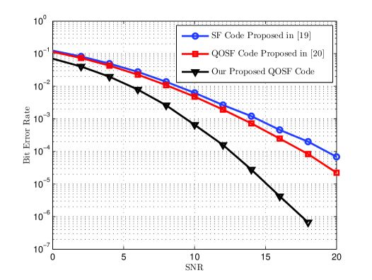
Fig. 2 shows the bit error rate (BER) performance of the proposed code in multipath propagation channels with a delay spread of τ=5μs𝜏5𝜇𝑠\tau=5\mu s. As shown in this figure, the proposed code outperforms those of [19] and [20]. In particular, at a bit error rate of 105superscript10510^{-5}, the performance improvement compared to [19] and [20] is nearly 777 and 666 dB, respectively. This performance improvement demonstrates the superiority of our proposed scheme which is due to the extra diversity gain offered by the use of reconfigurable antenna elements.

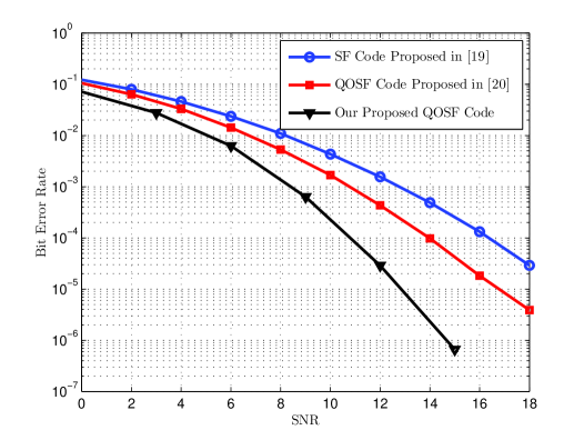
Fig. 3 depicts the BER performance of the proposed code for a delay spread of τ=20μs𝜏20𝜇𝑠\tau=20\mu s. It is evident from the figure that at a BER of 105superscript10510^{-5}, our proposed coding scheme outperforms the codes presented in [19] and [20] by about 666 and 444 dB, respectively. Compared to the results in Fig. 2, it can be seen that as delay spread increases, the BER performance improves. This is due to benefiting from lower correlation between subcarriers, and therefore higher frequency diversity in multipath propagation channels.

Refer to caption
Figure 3: BER vs. SNR for a reconfigurable multi-antenna system with Mt=2subscript𝑀𝑡2M_{t}=2, P=2𝑃2P=2, Mr=1subscript𝑀𝑟1M_{r}=1 in a 222-ray channel with a delay spread of 20μs20𝜇𝑠20\mu s

V Conclusions

We proposed a space-frequency coding technique for MIMO-OFDM systems using antennas with reconfigurable radiation patterns. The proposed code is constructed based on the principle of quasi-orthogonal coding scheme and consists of a block of transmitted symbols expanding over space, frequency, and radiation state dimensions. We provided simulation results to demonstrate the performance of the proposed coding scheme and make comparisons with that of the previous SF coding schemes. In these experiments, it has been shown that the proposed code provides additional diversity and coding gains compared to the previously designed SF codes in MIMO-OFDM systems.

References

  • [1] B. Cetiner, E. Akay, E. Sengul, and E. Ayanoglu, “A MIMO system with multifunctional reconfigurable antennas,” IEEE Antennas Wireless Propag. Lett., vol. 5, pp. 463–466, 2006.
  • [2] D. Piazza, N. Kirsch, A. Forenza, R. Heath, and K. Dandekar, “Design and evaluation of a reconfigurable antenna array for MIMO systems,” IEEE Trans. Antennas Propagat., vol. 56, pp. 869–881, Mar. 2008.
  • [3] J. Frigon, C. Caloz, and Y. Zhao, “Dynamic radiation pattern diversity (DRPD) MIMO using CRLH leaky-wave antennas,” in Proc. IEEE Radio and Wireless Symp., 2008, pp. 635–638.
  • [4] X. Li and J. Frigon, “Capacity analysis of MIMO systems with dynamic radiation pattern diversity,” in Proc. IEEE VTC Spring 2009, 2009, pp. 1–5.
  • [5] A. Grau, H. Jafarkhani, and F. De Flaviis, “A reconfigurable multiple-input multiple-output communication system,” IEEE Trans. on Wireless Commun., vol. 7, pp. 1719–1733, May 2008.
  • [6] W. Weedon, W. Payne, and G. Rebeiz, “MEMS-switched reconfigurable antennas,” in Antennas and Propagation Society International Symposium, 2001. IEEE, vol. 3, 2001, pp. 654–657.
  • [7] C. Caloz and T. Itoh, Electromagnetic metamaterials: transmission line theory and microwave applications.   Wiley-IEEE Press, 2005.
  • [8] C. won Jung, M.-j. Lee, G. Li, and F. De Flaviis, “Reconfigurable scan-beam single-arm spiral antenna integrated with RF-MEMS switches,” IEEE Trans. Antennas Propagat., vol. 54, pp. 455–463, Feb. 2006.
  • [9] F. Fazel, A. Grau, H. Jafarkhani, and F. Flaviis, “Space-time-state block coded MIMO communication systems using reconfigurable antennas,” IEEE Trans. on Wireless Commun., vol. 8, pp. 6019–6029, Dec. 2009.
  • [10] D. Agrawal, V. Tarokh, A. Naguib, and N. Seshadri, “Space-time coded OFDM for high data-rate wireless communication over wideband channels,” in Proc. IEEE Veh. Technol. Conf. (VTC), vol. 3, 1998, pp. 2232–2236.
  • [11] K. F. Lee and D. B. Williams, “A space-time coded transmitter diversity technique for frequency selective fading channels,” in in Proc. IEEE Sensor Array and Multichannel Signal Processing Workshop, March 2000, pp. 149–152.
  • [12] H. Bolcskei and A. J. Paulraj, “Space-frequency coded broadband OFDM systems,” in Proc. IEEE Wireless Commun. Networking Conf. (WCNC), vol. 1, Sept. 2000, pp. 1–6.
  • [13] B. Lu and X. Wang, “Space-time code design in OFDM systems,” in Proc. IEEE Global Commun. Conf. (GLOBECOM), vol. 2, Nov. 2000, pp. 1000–1004.
  • [14] R. S. Blum, Y. G. Li, J. H. Winters, and Q. Yan, “Improved space-time coding for MIMO-OFDM wireless communications,” IEEE Trans. Commun., vol. 49, pp. 1873–1878, Nov. 2001.
  • [15] Z. Hong and B. L. Hughes, “Robust space-time codes for broadband OFDM systems,” in Proc. IEEE Wireless Commun. Networking Conf. (WCNC), vol. 1, 2002, pp. 105–108.
  • [16] K. F. Lee and D. B. Williams, “A space-frequency transmitter diversity technique for OFDM systems,” in Proc. IEEE Global Commun. Conf. (GLOBECOM), vol. 3, 2000, pp. 1473–1477.
  • [17] A. F. Molisch, M. Z. Win, and J. H. Winters, “Space-time-frequency (STF) coding for MIMO-OFDM systems,” IEEE Commun. Lett., vol. 6, pp. 370–372, Sept. 2002.
  • [18] W. Su, Z. Safar, M. Olfat, and K. R. Liu, “Obtaining full-diversity space-frequency codes from space-time codes via mapping,” IEEE Trans. Signal Process., vol. 51, no. 11, pp. 2905–2916, Nov. 2003.
  • [19] W. Su, Z. Safar, and K. R. Liu, “Full-rate full-diversity space-frequency codes with optimum coding advantage,” IEEE Trans. Inf. Theory, vol. 51, pp. 229–249, Jan. 2005.
  • [20] F. Fazel and H. Jafarkhani, “Quasi-orthogonal space-frequency and space-time-frequency block codes for MIMO OFDM channels,” IEEE Trans. on Wireless Commun., vol. 7, pp. 184–192, Jan. 2008.
  • [21] O. Tirkkonen, “Optimizing space-time block codes by constellation rotations,” in Finnish Wireless Commun. Workshop (FWWC), Oct. 2001, pp. 59–60.
  • [22] N. Sharma and C. B. Papadias, “Improved quasi-orthogonal codes through constellation rotation,” IEEE Trans. Commun., vol. 51, pp. 332–335, March 2003.
  • [23] W. Su and X.-G. Xia, “Signal constellations for quasi-orthogonal space-time block codes with full diversity,” IEEE Trans. Inf. Theory, vol. 50, pp. 2331–2347, Oct. 2004.