Impact of Droplets on Inclined Flowing Liquid Films
Abstract
The impact of droplets on an inclined falling liquid film is studied experimentally using high-speed imaging. The falling film is created on a flat substrate with controllable thicknesses and flow rates. Droplets with different sizes and speeds are used to study the impact process under various Ohnesorge and Weber numbers, and film Reynolds numbers. A number of phenomena associated with droplet impact are identified and analysed, such as bouncing, partial coalescence, total coalescence, and splashing. The effects of droplet size, speed, as well the film flow rate are studied culminating in the generation of an impact regime map. The analysis of the lubrication force acted on the droplet via the gas layer shows that a higher flow rate in the liquid film produces a larger lubrication force, slows down the drainage process, and increases the probability of droplet bouncing. Our results demonstrate that the flowing film has a profound effect on the droplet impact process and associated phenomena, which are markedly more complex than those accompanying impact on initially quiescent films.
pacs:
47.55.D-, 47.15.gm, 47.55.df, 47.55.dr, 47.35.PqI Introduction
Droplet impact on solid or liquid interfaces is a ubiquitous and fascinating phenomenon in nature Martin (1993); Yarin (2005), and has a wide range of applications; these include inkjet-printing, spray-painting, spray-cooling, internal combustion engines, fire suppression, deposition of solder bumps on printed circuit boards, surface-cleaning, and cell-printing. The outcome after a droplet impacts on a surface is a fascinating problem and has received considerable attention in the literature dating back to over a century ago Worthington (1908). Various impacting substrates have been employed, ranging from dry Kolinski et al. (2014) and pre-wetted surfaces Cossali et al. (1997), surfaces with physical Range and Feuillebois (1998) and chemical heterogeneities Chen and Li (2010); Kannan and Sivakumar (2008), thin Wang and Chen (2000) and deep liquid layers Adomeit and Renz (2000); Blanchette and Bigioni (2009), porous media Ding and Theofanous (2011), heated Bernardin et al. (1997); Tran et al. (2012), sublimating Antonini et al. (2013), and electrically-conducting Deng and Gomez (2010), elastic membranes Pepper et al. (2008), and granular materials Marston et al. (2010). Non-Newtonian Bergeron et al. (2000); Smith and Bertola (2010), surfactant-laden Gatne et al. (2009), and liquid-metallic droplets Aziz and Chandra (2000); Dykhuizen (1994) have also been studied. Different outcomes of impact have been observed, such as bouncing, coalescence, partial coalescence, splashing. The transitions among different regimes have been investigated Cossali et al. (1997); Rioboo et al. (2003); Wang and Chen (2000).
Depending upon the choice of impacting surfaces and droplet physical properties, the impact dynamics can be extremely complex. Thus, analysing the accompanying phenomena during the impact process, and understanding the physics behind the phenomena are of critical importance. Generally, the impact dynamics of droplets is dominated by the interplay between surface tension, inertia, and viscous forces; this may be modified by the presence of non-Newtonian and/or physico-chemical and/or thermal effects. The relative importance of these forces can be quantified using dimensionless numbers, such as the Ohnesorge and Weber numbers. These dimensionless numbers are used widely in the investigation of droplet impact, e.g., in defining the regimes of impact Pan and Law (2007) and in developing empirical correlations Scheller and Bousfield (1995); Cossali et al. (1997).
Although droplet impact phenomena have been investigated for more than a century, it is the recent development of high-speed imaging that allows researchers to unveil the fast evolving dynamic features of the phenomena Thoroddsen et al. (2008). Many phenomena occurring during impact remain poorly understood, and continue to attract interest. These phenomena include the collapse of the gas layer beneath the droplet during the impact de Ruiter et al. (2012); Driscoll and Nagel (2011); Tran et al. (2013), the entrapment of air bubbles when a droplet impacts on a liquid surface Bouwhuis et al. (2012); Oguz and Prosperetti (1990), and the ejection of liquid sheets during the impact and its subsequent breakup into secondary droplets Thoraval et al. (2012); Thoroddsen et al. (2012). Bird et al. Bird et al. (2009) found that during the impact of droplets on angled or moving surfaces, the asymmetry leads to an azimuthal variation of the ejected rim, and the tangential component of impact can act to enhance or suppress a splash. Šikalo et al. Š. Šikalo et al. (2005) studied the impact of droplets on inclined dry and wetted surfaces, and found the bouncing on dry smooth or wetted surfaces, and no bouncing on rough surfaces. Gilet and Bush Gilet and Bush (2012) studied the bouncing of droplets on an inclined substrate with a thin layer of high-viscosity fluid, and analysed the contact time and the conversion of energy. The liquid layer with high viscosity was used to ensure a smooth impact surface which facilitates droplet bouncing. Despite the large number of studies on droplet impact, the impact of droplets on flowing liquid films, to the best of our knowledge, has not been studied. This is surprising since it is a common phenomenon occurring in many two-phase flows, such as annular flows Hewitt (1978), spray-cooling Kim (2007), and spray-painting. The interaction between the droplet and the flowing liquid film could produce unique dynamic features distinct from the impact phenomena on quiescent liquids. This will be the subject of the present paper.
A falling liquid film is used as the flowing liquid film for droplet impact in this study. Falling films are common in nature, important to many industrial applications, and are characterised by rich nonlinear dynamics Chang (1994); Chang and Demekhin (2002); Craster and Matar (2009); Kalliadasis et al. (2011). The pioneering study of Kapitza was performed half a century ago Kapitza and Kapitza (1948). Since then, the flow in falling liquid films has been studied extensively through experimental measurements Adomeit and Renz (2000); Zhou et al. (2009), low-dimensional modelling Scheid et al. (2006); Shkadov (1967), and full numerical simulations Gao et al. (2003). The effects of many factors that influence the flow in falling films have been investigated, such as the effects of thermocapillarity Frank and Kabov (2006), electric fields Jayaratne and Mason (1964); Tseluiko and Papageorgiou (2006), and surfactants Ji and Setterwall (1994); Strobel and Whitaker (1969). Different processes that may be involved in falling films have also been studied, such as heat transfer Scheid et al. (2008), mass transfer Yang and Wood (1992), chemical reactions Dabir et al. (1996), and phase change Palen et al. (1994). Even though the flow of falling liquid films has been widely studied in the literature, it still remains an important research topic and attracts the attention of researchers of various disciplines. In this study, we use high-speed imaging to examine the impact of droplets of controlled diameter, angle of incidence and speed, on isothermal falling films in order to explore how the film dynamics influence the impact phenomena. In addition to the Ohnesorge and Weber numbers, this system is also parameterised by the film Reynolds number, which is based on the film mean thickness and velocity. The results of our work show that the film dynamics have a profound effect on the impact process, giving rise to phenomena that are not observed in the quiescent film case.
The rest of this paper is organised as follows. The experimental system is described in Section II, including the falling film rig, the droplet generation unit, and the high-speed imaging system. The experimental results are presented in Section III. A regime map of droplet impact is created, and the effects of the Weber, Ohnesorge, and Reynolds numbers are studied by varying the impact speeds, the droplet sizes, and the flow rates of the falling film. A simple model based on lubrication theory is used to explain the bouncing phenomenon. Finally, concluding remarks are provided in Section IV.
II Experimental method
II.1 Falling liquid film
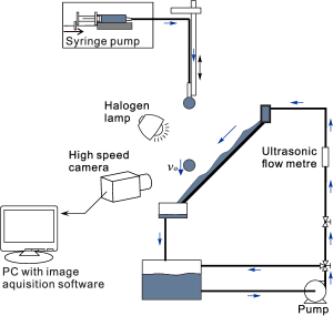
The experimental setup used to study droplet impact on flowing liquid films is shown in Figure 1. The falling film rig comprised a rigid and impermeable plate 41 cm long and 28 cm wide made of a titanium foil with a 50 m thickness inclined at 45∘ to the horizontal. The liquid used was deionised water of density kg/m3, viscosity Pas, and surface tension 72.8 mN/m, and the flow rate was controlled by a valve and a variac transformer for the pump. An ultrasonic flow metre (Flownetix 100 series, Flownetix, UK) was used to measure the flow rate of the falling film, which was in the range 0.90.1–10.70.3 l/min. The lower limit of the flow rate of the liquid film is the minimum flow rate that can ensure the whole substrate is wetted. The mean film thicknesses and the mean flow speed were estimated using the Nusselt solution Kalliadasis et al. (2011) to be in the range 0.29–0.65 mm, and 0.19–0.98 m/s, respectively. The Reynolds numbers of the falling films were therefore in the range 54–636, where and are the density and the viscosity of the liquid, and are the flow rate and the width of the falling liquid film, respectively. Since laminar-turbulence transition in falling films happens at Chang (1994), the flow in the falling liquid film studied here is laminar.
II.2 Droplet generation unit
Droplets of uniform size were generated from the tip of blunt syringe needles. Deionised (DI) water was pumped into the needle using a syringe pump (Braintree Scientific Inc., UK) at constant flow rates. The droplets broke up at the tip of the syringe needle in the dripping mode, fell under their own weights, and impacted obliquely onto the inclined liquid film. The dripping mode and the gravity-driven acceleration of the droplets ensure that the process is highly reproducible. To study the effect of droplet size on the impact process, the droplet size was varied via a change in the diameter of the needle. Three droplet diameters were studied, 3.3, 4.0, and 5.2 mm with standard deviation less than 0.1 mm, while the corresponding Ohnesorge number,, were 0.0021, 0.0019, and 0.0016, respectively. Here, is the density of the liquid, is the surface tension, is the dynamic viscosity, and is the droplet diameter before impact. To study the effect of the droplet speed on the impact process, the impact speeds of the droplets were varied by changing the vertical distance of the needle towards the falling liquid film from 1 to 50 cm. The corresponding speeds of the droplet were in the range 0.300.02–2.990.09 m/s, and the corresponding Weber numbers, , were in the range of 4–630 for different droplet sizes. The impact point on the liquid film is 34 cm from the inlet of the falling film, which is larger than 500 times of the film thickness of the Nusselt solution Kalliadasis et al. (2011) at the highest flow rate studied, and allows the development of the film flow on the substrate. The details of the flow in the falling film will be discussed in Subsection III.1.
II.3 high-speed imaging system
The droplet impact process was recorded using a high-speed camera (Olympus i-SPEED 3) at a frame rate of 5000 frames per second. A macro lens (Sigma EX 105mm) was used to capture the details during the impact. Two halogen lamps (500W) were used for illumination. To minimize the heating effect of the halogen lamps, the lamps were kept on only when the camera was recording. Side-view images were captured at a resolution of 804396 pixels (about 40 m/pixel) with 10∘ deviation from the plane of the film, while top view images were capture at a resolution of 528600 pixels perpendicular to the film (about 40 m/pixel). The high-speed images were analysed using customised Matlab routines. The speed and the size of the droplets were measured from the high-speed images.
III Results and discussion
In this section, we present a discussion of our results starting with a brief description of the wavy falling film dynamics in the absence of droplet impact; this provides an indication of the expected state of the interface prior to droplet impact at various film Re. A detailed investigation of the wavy flow in the liquid film is beyond the scope of this study. We then describe the main phenomena associated with the impact process, before presenting a flow regime diagram as a function of system parameters. The results of a simple model based on lubrication theory are also discussed, and used to explain the trends associated with a subset of the phenomena observed.
III.1 Wavy flow in liquid films
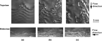
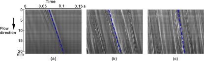
The wavy flow in the falling liquid films was analysed from the top-view and side-view images near the point of the droplet impact, as shown in Figure 2. At low Re values, the liquid films are characterised by interfaces that exhibit mild deformations with occasional solitary waves. These waves are formed with coherent precursor waves, as shown in Figure 2a. As Re increases, the waves become more frequent and less coherent. The evolution of the waves can be seen from the time-space plot of a line along the flow direction, which is obtained from the top-view images, as shown in Figure 3. In a time-space plot, the (spatial) wave length is the vertical distance of consecutive waves, and the (temporal) frequency of the waves is the reciprocal of the horizontal distance of consecutive waves. The amplitude of the waves could not be measured in this experiment quantitatively due to the limitation of the experimental facility. The variation of the film thickness, however, is represented by the light intensity. Previous studies of falling liquid films Chang (1994); Chang and Demekhin (2002); Craster and Matar (2009); Kalliadasis et al. (2011) have shown that the amplitude of the waves is usually smaller or comparable to the mean film thickness, and the wave lengths are much larger than the mean film thickness. The surface curvature of the liquid film is very small as compared to the droplet curvature due to the small aspect ratio of the liquid film (thickness vs film length). At low Re, the solitary wave in Figure 3a travels downstream at a constant speed. With increasing Re, the waves interact with adjacent waves as they propagate downstream, as shown in Figure 3b-c. The speed of the waves can be estimated from the gradient of the line of the waves in the time-space plot, which shows that the wave speed increases with Re.
In the following subsections, the impact processes on falling films at different conditions of We, Re, and Oh numbers are analysed. Various combinations of the parameters result in different phenomena as observed in the experiments: bouncing, partial coalescence, total coalescence, and splashing, as will be detailed below. Because the waves on the liquid films are formed naturally and stochastically, the drop may impact on different parts of the waves. Therefore, the outcome of the impact may vary, and the results are presented in a probability manner.
III.2 Bouncing
‘Bouncing’ refers to situations wherein a droplet approaching the falling film, does not coalesce with it, but instead bounces back, as shown in Figure 4, which was generated for , , and . The coalescence of a droplet with a liquid film involves three stages: (i) droplet approach towards the film; (ii) the thinning of the thin, intervening gas layer between the droplet and the film; and (iii) the rupture of the gas layer. The first stage is driven by the momentum of the droplet gained from gravity, the second stage is resisted by the viscous force in the thin gas layer, and the third stage is dominated by capillary force. As the gas layer becomes thinner, the resistance becomes larger, according to lubrication theory Davis et al. (1989); Deen (1998). Therefore, the gas layer could potentially stabilise the droplet against coalescence. Rupture of the gas layer occurs when its thickness decreases below a certain level so that van der Waals forces come into operation to destabilise the layer Hahn et al. (1985).
Prior to impact, the droplet is almost spherical (see Figure 4a), as the capillary force minimizes the surface area and, in turn, the surface energy. Upon impact, the droplet progressively adopts a pyramidal (see Figure 4e) and then a pancake shape (see Figure 4g). The latter increases the contact area of the droplet with the film and further retards the thinning of the gas layer, according to lubrication theory Davis et al. (1989); Deen (1998). The surface energy of the droplet, , can be estimated through image analysis by assuming a surface of revolution, , where is the surface area of the droplet. The result shows that from the undistorted droplet shape (see Figure 4 c) to the maximum deformation (see Figure 4g), the surface energy increases from approximately J to J. Meanwhile, the kinetic energy before the impact, , and the loss of potential energy, , are approximately J and J, respectively. Here, is the mass of the droplet, and is the vertical distance that the droplet travels from the instant of apparent contact to the instant of maximum deformation. Therefore, the relative conversion of energy from kinetic and potential energy to surface energy during the process can be calculated from
| (1) |
which is estimated to be about 70%. Such high ratio of energy conversion has also been found for droplet bouncing on horizontal and inclined wet surfaces Gilet and Bush (2012).
The Weber number is a key parameter that affects the thinning of the gas layer prior to possible rupture: lower Weber numbers (lower impact speeds) lead to longer gas layer drainage times, and, therefore, an increased probability of droplet bouncing. The momentum of the falling film, on the other hand, for a fixed inclination angle, increases with the film Reynolds number (the liquid flow rate). Therefore, droplets have a greater chance of bouncing on liquid films with higher Reynolds numbers. This is consistent with the phenomenon of droplet levitation at the hydraulic jump point of a liquid film produced from a vertical jet impinging on a horizontal surface Sreenivas et al. (1999). The details will be explained in detail in Section III.7.
III.3 Partial coalescence
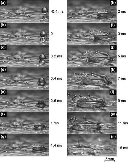
For a range of system parameters, the droplets were observed to undergo ‘partial coalescence’ with the falling film. This corresponds to situations wherein, upon impacting the film, a fraction of the droplet coalesces with the film, but immediately after impact, a small daughter droplet or a cascade of daughter droplets Blanchette and Bigioni (2006); Gilet et al. (2007) are created; an example of partial coalescence is shown in Figure 5. It occurs as a consequence of small Weber numbers and small film Reynolds numbers.
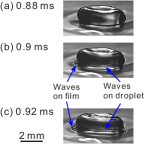
The rupture of the gas layer starts with the formation of a liquid bridge connecting the droplet and the liquid film. Due to the large curvature at the liquid bridge and the corresponding large capillary force, the liquid bridge immediately grows, and produces capillary waves on the surface of the droplet and on the liquid film (see Figure 5g and Figure 6 for the formation and the propagation of the capillary waves). The waves on the droplet then propagate rapidly towards the apex of the droplets (see Figure 6c). Immediately after the collapse of the gas layer, the liquid at the bottom of the droplet is significantly affected by the capillary waves and is pulled towards the liquid film. However, the liquid at the droplet apex is less affected, and there is no sufficient time to catch up with that near the bottom of the droplet. Therefore, the droplet becomes a long thin liquid thread (see Figure 5l), which eventually breaks up into two parts (see Figure 5o) due to the inward momentum of the collapsing neck Blanchette and Bigioni (2006). The lower part mixes with the liquid in the falling film, while the upper part gradually falls on the liquid film due to gravity as a daughter droplet. The daughter droplet tends to be more stable against coalescence because of its smaller speed than the primary droplet before partial coalescence, as shown in Figure 5p.
The surface energy after pinch-off of the daughter droplet (see Figure 5n) can be estimated through image analysis to be J. It is much smaller than the initial surface energy before the impact (see Figure 5a), J. This indicates significant energy loss due to viscous dissipation and the formation of capillary waves during the process.
III.4 Total coalescence
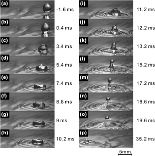
In contrast to the situations considered above, ‘total coalescence’ refers to complete coalescence of the droplet with the falling film upon impact without forming smaller, secondary droplets; an example of total coalescence is shown in Figure 7 generated for , , and . If the Weber number is above a certain level, the upper part of the droplet, follows the lower part of the droplet and coalesces with the liquid film (see Figure 7f), without breaking up into a daughter droplet, as in the case of partial coalescence. In addition, the high-momentum liquid in the droplet pushes away the liquid in the flowing film and produces a crater (see Figure 7g). The waves produced by this event propagate away from the crater and dissipate gradually (see Figure 7h).
III.5 Splashing
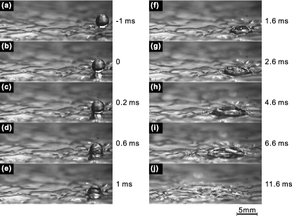
If the momentum of the droplet is sufficiently large, characterised by high We, the droplet drives the liquid in the film to form a ‘crown’, which then disintegrates into many droplets, as shown in Figure 8. This ‘splashing’ phenomenon occurs because the gas layer separating the impacting droplet and the falling film undergoes rapid rupture, and capillary forces are not sufficiently strong so as to balance the large force per unit area at high Weber numbers. Thus, following impact, the liquid undergoes severe deformation leading to the formation of a cylindrical sheet of liquid around the droplet (see Figure 8e), which then assumes a crown shape (see Figure 8h). The crown rim then undergoes an Rayleigh-Plateau instability Zhang et al. (2010) that results in the creation and subsequent ejection of small droplets (see Figure 8k). The crown formation and the ejection of small droplets for the impact of droplets on quiescent liquids has been well studied in the literature Martin (1993); Wang and Chen (2000); Yarin (2005); Thoraval et al. (2012); Thoroddsen et al. (2012). Being different from impact on quiescent liquids, the wavy interface of the liquid film results in a more irregular crown structure and different sizes of the small droplets. The crown is also not symmetric due to the oblique impact angle Bird et al. (2009): the rim on the downstream side is much higher than that on the upstream side of the crown, which leads to the ejection of more droplets on the downstream side. The details will be discussed in Subsection III.9.
III.6 Regime map
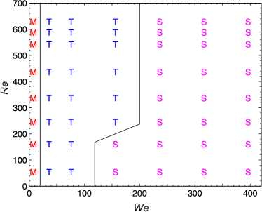
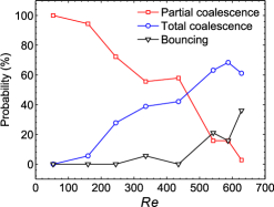
A regime map for droplet impact on falling liquid films is created by varying the flow rate of the falling film and the impact speed of the droplets; this is presented in Figure 9 as a Re vs We plot which shows the regime transitions as these parameters are varied for . For a given Re, large We values lead to splashing, while moderate We values lead to total coalescence. At the lowest We studied, multiple phenomena are observed, namely bouncing, partial coalescence, and total coalescence, and their probability of occurrence in repeated experiments are plotted in Figure 10.
As shown in Figure 10, partial coalescence always occurs for the lowest Re studied. As Re increases, the probability of partial coalescence decreases, while that of total coalescence rises. This is because a thick liquid film facilitates the flow of liquid in the direction perpendicular to the film and allows the liquid near the top region of the droplet to catch up with that near the bottom region, thereby reducing the probability of formation of secondary droplets following impact. The probability of bouncing also increases with the film Reynolds number. This is consistent with the phenomenon of droplet levitation at the hydraulic jump point of a liquid film produced from a vertical jet impinging on a horizontal surface Sreenivas et al. (1999), which corresponds to a large Re and negligible We in Figure 9.
III.7 Lubrication gas layer and force analysis
To explain the phenomena presented above, the gas layer between the droplet and the liquid film and the forces involved are analysed. Prior to the rupture of the gas layer between the droplet and the liquid film, the gas layer drains gradually. The drainage of the gas layer is controlled by the competition between the inertia of the approaching droplet and the lubrication force in the gas layer. The former serves as the driving force and is indicated by the normal component of the droplet speed to the falling film, while the latter serves as the resistance and is affected by the flow speed in the film. Thus, droplet bouncing is expected only at low normal speeds of impact. Even though the thickness of the gas layer is too thin to be determined from the observation in Figure 4, measurements of the film thickness for droplet impact on solid surfaces in the literature van der Veen et al. (2012); de Ruiter et al. (2012) have shown that the thickness of the gas layer can be down to several micrometres. To estimate the lubrication force acted on the droplet by the gas layer during the impact process, two complementary methods are presented. The first method is through an analysis of the flow in the gas layer, the liquid film, and the droplet, while the second method relies on the analysis of the droplet deformation shown on the high-speed images.
III.7.1 Estimation from the flow in the gas layer, the liquid film, and the droplet
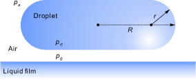
Due to the small thickness of the gas layer and the liquid film relative to the drainage length of the gas layer in the tangential direction, the flow in the gas layer and in the liquid film can be approximated using lubrication theory. The approximation is also applied in a penetration depth in the droplet, and the velocity gradient vanishes and the velocity approaches the droplet tangential speed at the penetration depth Li and Liu (1996); Yeo et al. (2001), as shown in Figure 11. We also neglect deformations of the film-gas interface in the present, approximate analysis:
| (2) |
| (3) |
| (4) |
where the subscript indicates the gas layer, and the liquid film, and the droplet. Then the velocity profiles along the direction are parabolic:
| (5) |
| (6) |
| (7) |
where the coefficients , , , , , , , , can be obtained by satisfying the following boundary conditions and closure equations. A no-slip boundary condition is imposed at the substrate, and continuity of velocity is imposed at the gas/liquid-film interface and at the gas/droplet interface,
| (8) |
| (9) |
| (10) |
where . The matching of shear stress at the gas/liquid-film interface and at the gas/droplet interface yields
| (11) |
| (12) |
The shear stress at the penetration depth of the droplet vanishes, and the speed approaches the tangential speed of the droplet with respect to the substrate, :
| (13) |
| (14) |
where . The flow rate of the liquid film is given by
| (15) |
The pressure gradients in the liquid film and in the gas layer are assumed to be the same because film deformations are neglected, and normal viscous stresses correspond to high-order terms within lubrication theory; thus, Eqs. (2) and (3) yield
| (16) |
Therefore, the coefficients in Eqs. (5)–(6) can be obtained:
| (17) | ||||||||
where
Although the exact value of pressure could not be known due to the complex structure at the rim of the gas layer, the pressure difference between the gas layer and the ambient can be estimated from the pressure gradient,
| (18) |
where we have made use of Eqs. (2), (5), (16), and (17). Therefore, the lubrication force can be estimated as
| (19) |
The liquid film thickness can be estimated from the Nusselt solution for the falling liquid film Kalliadasis et al. (2011),
| (20) |
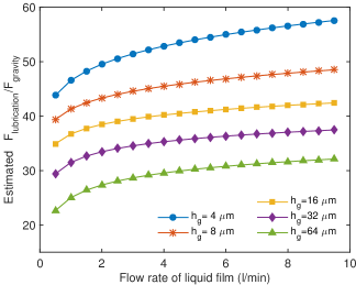
The penetration depth in the droplet is assumed to be as in Ref. Yeo et al. (2001). Therefore, during the drainage of the gas layer, the magnitude of the lubrication force can be estimated at different thicknesses of the gas layer, as shown in Figure 12. The lubrication force (i.e., the resistant force) being large than the normal component of the gravitational force (i.e., the driving force) is a minimum requirement of droplet bouncing. Therefore, the gravitational force of the droplet in the direction normal to the falling film, , is used as a reference to scale the estimated lubrication force, where is the inclination angle of the falling film to the horizontal. Figure 12 shows that as the gas layer becomes thinner, the lubrication force becomes larger. It also shows that the lubrication force increases with increasing the film flow rate. Since a large lubrication force indicates a large resistance of the droplet, a slow drainage of the gas layer, and a high chance of droplet bouncing, the result in Figure 12 is consistent with the experimental observation shown in Figure 10.

III.7.2 Estimation from the droplet deformation in high-speed images
The force applied on the droplet by the falling liquid film via the gas layer can also be estimated from the droplet deformation in the high-speed images. When the droplet reaches the maximum deformation, it has a pancake shape, as shown in Figure 4g. The pressure in the droplet can be estimated through the surface curvature of the droplet,
| (21) |
where the and are two principle radii of the curved droplet interface measured on the side of the non-spherical droplet, as shown Figure 13. Since the base of the droplet is almost flat and does not deform rapidly during the later stage of the drainage of the gas layer, the pressure in the droplet and in the gas layer can be regarded to be in equilibrium, and the pressure in the gas layer, , can be approximated by the pressure in the droplet, ,
| (22) |
The lubrication force applied on the droplet by the liquid film via the gas layer can be estimated by multiplying the pressure in the gas layer and the base area of the droplet, . Therefore, the lubrication force is
| (23) |
where the effect of the ambient pressure in Eq. (22) is cancelled by the ambient pressure on the upper side of the droplet. For the bouncing event shown in Figure 4, image analysis shows that the ratio of the lubrication force to the gravitational force . Therefore, the lubrication force by the gas layer on the droplet can be much larger than the gravitational force of the droplet, and can result in bouncing.
At impact, both the gas-droplet and gas-film interfaces undergo deformation Tran et al. (2013) whose severity depends on the system parameters. An estimate of the liquid film deformation is obtained by comparing inertial, capillary, and viscous forces. The inertial force tends to deform the interface, while the capillary and viscous forces tend to resist this deformation. Their relative importance can be quantified by their ratios represented by the Weber number and the Reynolds number for film deformation, respectively given by:
| (24) |
| (25) |
The characteristic velocity is the normal velocity of droplet towards the plate, , while the characteristic length is the film thickness as calculated from the Nusselt solution Kalliadasis et al. (2011). At an impact speed of 0.30 m/s, for instance, , and , which indicate that the surface tension is very important in resisting the deformation of the film interface. Equations (24–25) also indicate that thicker films which correspond to high film Re are easy to deform. In addition, the relative importance between the viscous and capillary forces is quantified by
| (26) |
which is in the range of 0.003–0.03 for different impact speeds (0.30–2.99 m/s), indicating that the capillary force is much stronger than the viscous force.
During impact, at larger Re values of the liquid films, the average liquid films are thicker and more deformable since the restoring capillary force becomes progressively weaker. The deformation of the gas/liquid-film interface delays the drainage of the gas layer, preventing its rupture. In addition, the force exerted by the film on the droplet at high film Re, which is transmitted through the gas layer, pushes the droplet away from the impact region. These factors also could increase the probability of droplet bouncing.
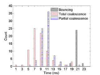
To further understand the collapse of the gas layer, the lifetime of the gas layer was studied, and a histogram of this lifetime is plotted in Figure 14. The starting time was determined from the high-speed images, which show noticeable capillary waves on the surfaces of the liquid film upon apparent impact. The ending time was determined from the images which show the rupture of the gas layer indicated by the capillary waves on the droplet and on the liquid film, as explained in Figure 6. For the bouncing phenomenon, the lift-off of the droplet away from the film was considered as the ending time. Due to this distinctive feature and the fast propagation of the capillary waves in the high-speed images, the life time of the gas layer can be determined at an accuracy of about 0.2–0.4 ms at the filming frame rate 5000 fps. As shown in Figure 14, the bouncing and total coalescence phenomena correspond to long and short gas layer lifetimes, respectively. This indicates that delaying (accelerating) the rupture of the gas layer results in bouncing (total coalescence). This is because the speed of the liquid at the top region of the droplet can be retarded via droplet deformation during the thinning of the gas layer. Following rapid rupture of the gas layer, the fluid near the droplet apex has a higher chance of catching up with the fluid near the bottom of the droplet, preventing the formation of secondary droplets, and leading to total coalescence.
III.8 Dimple formation and droplet ejection for large droplets
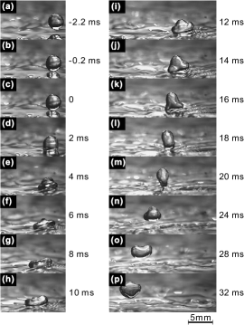
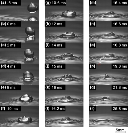
The Ohnesorge number can be varied by changing the droplet size. We consider a case shown in Figure 15 characterised by , , and . These parameters are similar to those that were used to generate Figure 5, which depicted a case of partial coalescence; the decrease in Oh and the slight increase in We were brought about by the increase in the droplet diameter from 3.3 mm to 5.2 mm. The case presented in Figure 14 illustrates an impact accompanied by the droplet surface switching from a convex to a concave shape, followed by the ejection of a small droplet. Inspection of Figure 14a shows that the droplet shape prior to impact is far from spherical, as expected for large droplet size, i.e., large Oh numbers. Upon apparent contact with the liquid film (see Figure 15b), capillary waves are formed and propagate along the surface of the droplet towards the top of the droplet and also on the surface of the liquid film (see Figure 15c-d). The liquid in the top region of the droplet is less affected by the impact than that near the bottom of the droplet and continues to move towards the film by inertia (see Figure 15e-f). Following rupture of the gas layer, capillary waves form and propagate on the surface of the droplet towards its apex. The interaction of these waves with the downwards-moving fluid from the apex leads to the formation of a hat-shaped droplet (see Figure 15g-h) followed by a dimple at the droplet apex (see Figure 15i-k). The formation of the dimple is facilitated by the relative weakness of capillary forces for such large droplets and their consequent inability to act as effective restoring forces to counterbalance severe interfacial deformation. For the concave interface associated with the dimple, capillarity pulls the liquid at the rim of the dimple causing it to shrink (see Figure 15l-n). The collision of the interface at the rim of the dimple results in the ejection of a small droplet (see Figure 15o-p). Due to the flow in the liquid film, the droplet is not symmetric, and the small droplet is ejected in a direction which is not perpendicular to the substrate but deviated in the streamwise direction. The liquid eventually settles down as the energy from the impact is dissipated gradually (see Figure 15q-r).
III.9 The asymmetric splashing process
We devote the concluding part of this section to quantitatively examining the details of asymmetric splashing at different film flow rates, droplet speeds, and droplet sizes. The asymmetric splashing process was studied to consider the effects of relevant parameters and quantified by the propagation of the baseline of the droplet, as shown in Figure 16a. The streamwise direction of the falling film is defined as the positive direction of the movement of the baseline, and the initial contact point of the droplet on the falling liquid film is defined as the origin. The initial contact time is determined by interpolating the interface position from the image sequence, which provides a higher precision of the initial contact time than the time delay between two consecutive frames. The length of the baseline of the droplet, and the position of the front and rear point is normalized by the diameter of the droplet, and the time is normalized by the speed and the diameter of the droplet:
| (27) |
| (28) |
Since the droplet impact in the present study is different from the perpendicular impact of droplets on quiescent films, the propagation of the front and rear of the baselines are asymmetric, as shown in Figure 16. The degree of asymmetry is influenced by the oblique impact of the droplet and the flow rate of the liquid film. Upon impact, the front point of the baseline moves along the flow direction, and the rear point of the baseline moves backwards. In addition, the front point moves at a higher speed than the rear point.
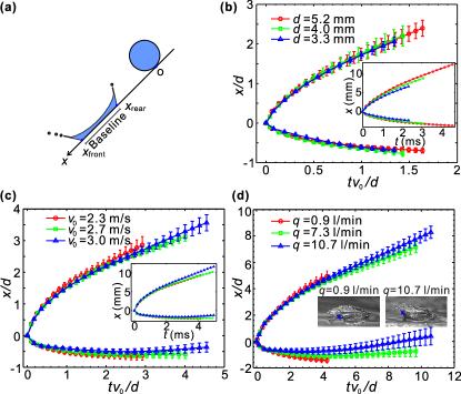
The effect of the droplet size on the asymmetric splashing process is shown in Figure 16b. The curves of the baselines for different droplet sizes collapse, even though the dimensional data show clear difference at different droplet sizes (see the inset plot of Figure 16b). For smaller droplets, the baselines propagate much more slowly at both the front and the rear of the droplets, and the splashing process is much shorter than that for large droplets. This is because the mass and the momentum introduced into the film by small droplets are much less than those by large droplets.
The propagation of the baseline for droplet impact at different droplet speeds is shown in Figure 16c. The propagation of the baseline appears to be weakly dependent on the droplet speed. The dimensional plot (see the inset plot of Figure 16c) shows that with increasing the droplet speed, both the front and the rear points move faster in the downstream direction. This is mainly due to the fact that droplets with higher speeds (larger momentum) can overcome the resistance of impact and move faster downstream than droplets with lower speeds.
The effect of the film flow rate on the propagation of the baseline is shown in Figure 16d. At a small flow rate, the liquid film is thin, and the liquid sheet of the crown is ejected close to the substrate. In contrast, at a high flow rate, the liquid film is thicker, and the liquid sheet of the crown is ejected close to the direction perpendicular to the substrate, as shown in the inset images of Figure 16d. Similar phenomena also exist for droplet impact on quiescent liquid films Wang and Chen (2000). Therefore, at a low film flow rate, the movement of the liquid sheet of the crown can promote the movement of the droplet baseline. With increasing the film flow rate, the film thickness increases, and the motion enhancing effect of the crown decrease. Consequently, the speeds of the front and rear points reduce. If the film flow rate increases further, the flow speed in the falling film also increases to the point where the film simply transports the droplet downstream so that both the front and rear points move in the streamwise direction.
IV Conclusion
In this paper, the oblique impact of droplets on inclined falling liquid films was studied using high-speed imaging. The results of droplet impact on flowing liquid films showed unique features different from the impact process on quiescent liquids. Under different impact conditions, various impact phenomena were observed: droplet bouncing, partial coalescence, total coalescence, and splashing. An impact regime map was generated for the impact of droplets on falling liquid films. Splashing phenomena occur at large Weber numbers, We, while other phenomena manifest themselves at low We. Low Reynolds numbers of the liquid films, Re, are associated with partial coalescence, while the probability of bouncing and total coalescence increases with Re. Dimple formation and droplet ejection were observed for the impact of large droplets. Splashing processes were quantified through the propagation of the droplet baselines during impact, and the effects of the droplet size, the droplet speed, and the flow rate of the falling liquid film were analysed. The analysis of the lubrication force during the impact process shows that a higher flow rate in the liquid film produces a larger lubrication force, slows down the drainage process, and increases the probability of droplet bouncing.
The study mainly focused on the fluid dynamics of the droplet impact on falling liquid films. There are many open questions related to droplet impact that are worthy of investigation, such as the direct measurement of the flow field during the impact process, the evolution of the gas layer, and the effects of droplet impact on the flow in the liquid films. In various relevant applications, such as annular flow, spray cooling, and spray painting, the impact processes are much more complex. For example, the impact of swarms of droplets on liquid films involves the interaction of numerous impact processes; the flow of the gas phase may induce turbulence in the liquid films and droplet entrainment on the film surface. This investigation will deepen our understanding of the physics involved in the phenomena of droplet impact, leading to a marked improvement in processes and applications that rely on these phenomena.
Acknowledgements
We would like to acknowledge the support of the Engineering and Physical Sciences Research Council, UK, through the Programme Grant, MEMPHIS (EP/K003976/1).
References
- Martin (1993) R. Martin, Fluid Dynamics Research 12, 61 (1993).
- Yarin (2005) A. L. Yarin, Annual Review of Fluid Mechanics 38, 159 (2005).
- Worthington (1908) A. M. Worthington, A Study of Splashes (Longmans Green and Co., New York, 1908).
- Kolinski et al. (2014) J. M. Kolinski, L. Mahadevan, and S. M. Rubinstein, Physical Review Letters 112, 134501 (2014).
- Cossali et al. (1997) G. E. Cossali, A. Coghe, and M. Marengo, Experiments in Fluids 22, 463 (1997).
- Range and Feuillebois (1998) K. Range and F. Feuillebois, Journal of Colloid and Interface Science 203, 16 (1998).
- Chen and Li (2010) L. Chen and Z. Li, Physical Review E 82, 016308 (2010).
- Kannan and Sivakumar (2008) R. Kannan and D. Sivakumar, Colloids and Surfaces A: Physicochemical and Engineering Aspects 317, 694 (2008).
- Wang and Chen (2000) A.-B. Wang and C.-C. Chen, Physics of Fluids 12, 2155 (2000).
- Adomeit and Renz (2000) P. Adomeit and U. Renz, International Journal of Multiphase Flow 26, 1183 (2000).
- Blanchette and Bigioni (2009) F. Blanchette and T. P. Bigioni, Journal of Fluid Mechanics 620, 333 (2009).
- Ding and Theofanous (2011) H. Ding and T. G. Theofanous, Journal of Fluid Mechanics 691, 546 (2011).
- Bernardin et al. (1997) J. D. Bernardin, C. J. Stebbins, and I. Mudawar, International Journal of Heat and Mass Transfer 40, 247 (1997).
- Tran et al. (2012) T. Tran, H. J. J. Staat, A. Prosperetti, C. Sun, and D. Lohse, Physical Review Letters 108, 036101 (2012).
- Antonini et al. (2013) C. Antonini, I. Bernagozzi, S. Jung, D. Poulikakos, and M. Marengo, Physical Review Letters 111, 014501 (2013).
- Deng and Gomez (2010) W. Deng and A. Gomez, Physics of Fluids 22, 051703 (2010).
- Pepper et al. (2008) R. E. Pepper, L. Courbin, and H. A. Stone, Physics of Fluids 20, 082103 (2008).
- Marston et al. (2010) J. O. Marston, S. T. Thoroddsen, W. K. Ng, and R. B. H. Tan, Powder Technology 203, 223 (2010).
- Bergeron et al. (2000) V. Bergeron, D. Bonn, J. Y. Martin, and L. Vovelle, Nature 405, 772 (2000).
- Smith and Bertola (2010) M. I. Smith and V. Bertola, Physical Review Letters 104, 154502 (2010).
- Gatne et al. (2009) K. P. Gatne, M. A. Jog, and R. M. Manglik, Langmuir 25, 8122 (2009).
- Aziz and Chandra (2000) S. D. Aziz and S. Chandra, International Journal of Heat and Mass Transfer 43, 2841 (2000).
- Dykhuizen (1994) R. C. Dykhuizen, Journal of Thermal Spray Technology 3, 351 (1994).
- Rioboo et al. (2003) R. Rioboo, C. Bauthier, J. Conti, M. Voué, and J. De Coninck, Experiments in Fluids 35, 648 (2003).
- Pan and Law (2007) K. L. Pan and C. K. Law, Journal of Fluid Mechanics 587, 1 (2007).
- Scheller and Bousfield (1995) B. L. Scheller and D. W. Bousfield, AIChE Journal 41, 1357 (1995).
- Thoroddsen et al. (2008) S. T. Thoroddsen, T. G. Etoh, and K. Takehara, Annual Review of Fluid Mechanics 40, 257 (2008).
- de Ruiter et al. (2012) J. de Ruiter, J. M. Oh, D. van den Ende, and F. Mugele, Physical Review Letters 108, 074505 (2012).
- Driscoll and Nagel (2011) M. M. Driscoll and S. R. Nagel, Physical Review Letters 107, 154502 (2011).
- Tran et al. (2013) T. Tran, H. de Maleprade, C. Sun, and D. Lohse, Journal of Fluid Mechanics 726, R3 (2013).
- Bouwhuis et al. (2012) W. Bouwhuis, R. C. A. van der Veen, T. Tran, D. L. Keij, K. G. Winkels, I. R. Peters, D. van der Meer, C. Sun, J. H. Snoeijer, and D. Lohse, Physical Review Letters 109, 264501 (2012).
- Oguz and Prosperetti (1990) H. N. Oguz and A. Prosperetti, Journal of Fluid Mechanics 219, 143 (1990).
- Thoraval et al. (2012) M.-J. Thoraval, K. Takehara, T. G. Etoh, S. Popinet, P. Ray, C. Josserand, S. Zaleski, and S. T. Thoroddsen, Physical Review Letters 108, 264506 (2012).
- Thoroddsen et al. (2012) S. T. Thoroddsen, K. Takehara, and T. G. Etoh, Journal of Fluid Mechanics 706, 560 (2012).
- Bird et al. (2009) J. C. Bird, S. S. Tsai, and H. A. Stone, New Journal of Physics 11, 063017 (2009).
- Š. Šikalo et al. (2005) Š. Šikalo, C. Tropea, and E. N. Ganić, Journal of Colloid and Interface Science 286, 661 (2005).
- Gilet and Bush (2012) T. Gilet and J. W. M. Bush, Physics of Fluids 24, 122103 (2012).
- Hewitt (1978) G. F. Hewitt, Measurement of Two Phase Flow Parameters, Vol. 79 (Academic Press, 1978).
- Kim (2007) J. Kim, International Journal of Heat and Fluid Flow 28, 753 (2007).
- Chang (1994) H. Chang, Annual Review of Fluid Mechanics 26, 103 (1994).
- Chang and Demekhin (2002) H. Chang and E. A. Demekhin, Complex Wave Dynamics on Thin Films (Elsevier Science, 2002).
- Craster and Matar (2009) R. Craster and O. Matar, Reviews of Modern Physics 81, 1131 (2009).
- Kalliadasis et al. (2011) S. Kalliadasis, C. Ruyer-Quil, B. Scheid, and M. G. Velarde, Falling Liquid Films (Springer, 2011).
- Kapitza and Kapitza (1948) P. L. Kapitza and S. P. Kapitza, Journal of Experimental and Theoretical Physics 19, 105 C120 (1948).
- Zhou et al. (2009) D. W. Zhou, T. Gambaryan-Roisman, and P. Stephan, Experimental Thermal and Fluid Science 33, 273 (2009).
- Scheid et al. (2006) B. Scheid, C. Ruyer-Quil, and P. Manneville, Journal of Fluid Mechanics 562, 183 (2006).
- Shkadov (1967) V. Y. Shkadov, Fluid Dynamics 2, 29 (1967).
- Gao et al. (2003) D. Gao, N. B. Morley, and V. Dhir, Journal of Computational Physics 192, 624 (2003).
- Frank and Kabov (2006) A. M. Frank and O. A. Kabov, Physics of Fluids 18, 032107 (2006).
- Jayaratne and Mason (1964) O. W. Jayaratne and B. J. Mason, Proceedings of the Royal Society of London A: Mathematical, Physical and Engineering Sciences 280, 545 (1964).
- Tseluiko and Papageorgiou (2006) D. Tseluiko and D. T. Papageorgiou, Journal of Fluid Mechanics 556, 361 (2006).
- Ji and Setterwall (1994) W. Ji and F. Setterwall, Journal of Fluid Mechanics 278, 297 (1994).
- Strobel and Whitaker (1969) W. J. Strobel and S. Whitaker, AIChE Journal 15, 527 (1969).
- Scheid et al. (2008) B. Scheid, S. Kalliadasis, C. Ruyer-Quil, and P. Colinet, Europhysics Letters 84, 64002 (2008).
- Yang and Wood (1992) R. Yang and B. D. Wood, Solar Energy 48, 195 (1992).
- Dabir et al. (1996) B. Dabir, M. R. Riazi, and H. R. Davoudirad, Chemical Engineering Science 51, 2553 (1996).
- Palen et al. (1994) J. W. Palen, Q. Wang, and J. C. Chen, AIChE Journal 40, 207 (1994).
- Davis et al. (1989) R. H. Davis, J. A. Schonberg, and J. M. Rallison, Physics of Fluids A: Fluid Dynamics 1, 77 (1989).
- Deen (1998) W. M. Deen, Analysis of Transport Phenomena (Oxford University Press, New York, 1998).
- Hahn et al. (1985) P.-S. Hahn, J.-D. Chen, and J. C. Slattery, AIChE Journal 31, 2026 (1985).
- Sreenivas et al. (1999) K. R. Sreenivas, P. K. De, and J. H. Arakeri, Journal of Fluid Mechanics 380, 297 (1999).
- (62) See Supplemental Material at [URL will be inserted by publisher] for 5 movies of droplet impact on falling liquid films.
- Blanchette and Bigioni (2006) F. Blanchette and T. P. Bigioni, Nature Physics 2, 254 (2006).
- Gilet et al. (2007) T. Gilet, K. Mulleners, J. P. Lecomte, N. Vandewalle, and S. Dorbolo, Physical Review E 75, 036303 (2007).
- Zhang et al. (2010) L. V. Zhang, P. Brunet, J. Eggers, and R. D. Deegan, Physics of Fluids 22, 122105 (2010).
- van der Veen et al. (2012) R. van der Veen, T. Tran, D. Lohse, and C. Sun, Physical Review E 85, 026315 (2012).
- Li and Liu (1996) D. Li and S. Liu, Langmuir 12, 5216 (1996).
- Yeo et al. (2001) L. Y. Yeo, O. K. Matar, E. P. de Ortiz, and G. F. Hewitt, Journal of Colloid and Interface Science 241, 233 (2001).