Confined linear carbon chains: a route to bulk carbyne
Abstract
The extreme instability and strong chemical activity of carbyne, the infinite hybridized carbon chain, are responsible for its low possibility to survive at ambient conditions. Therefore, much less has been possible to explore about carbyne as compared to other novel carbon allotropes like fullerenes, nanotubes and graphene. Although end-capping groups can be used to stabilize a carbon chain, length limitation is still a barrier for its actual production, and even more for applications. Here, we report on a novel route for bulk production of record long acethylenic linear carbon chains protected by thin double-walled carbon nanotubes. A corresponding extremely high Raman band is the first proof of a truly bulk yield formation of very long arrangements, which is unambiguously confirmed by transmission electron microscopy. Our production establishes a way to exceptionally long stable carbon chains, and an elegant forerunner towards the final goal of a bulk production of essentially infinite carbyne.
Faculty of Physics, University of Vienna, 1090 Wien, Austria
National Institute of Advanced Industrial Science and Technology (AIST), Nanotube Research Centre, 305-8565 Tsukuba, Japan
Different kinds of allotropes can be formed from elemental carbon due to its hybridization[1]. Well known are diamond and tetrahedral amorphous carbon as hybridized solids, whereas hybridization is present in graphite, fullerenes[2], carbon nanotubes (CNTs)[3] and graphene[4]. All of them have been intensively investigated in the last decades. However, since carbyne was proposed, as third allotrope as infinite chain with hybridization in the sixties of the last century, its research attracted great interest but also significant controversy[5, 6, 7, 8]. For several years the identification of carbyne remained questionable[9, 10] until the experimental accomplishment to unambiguously produce polyynes: short hybridized linear carbon arrangements with end-capping groups. The longest reported polyynes so far consist of 44 contiguous carbon atoms with alternating single and triple bonds[11], but the bulk synthesis of carbyne or very long linear carbon chains (LLCCs) continues to face stumbling blocks. Very little is known about the hybridization in carbyne because of its extreme instability in ambient conditions. In fact, a longstanding study postulated the impossibility to prepare this truly 1D material[12]. Although the same had been foreseen for graphene on account of its thermodynamic instability, its rise initiated by a feasible synthesis route and the later understanding of its unique properties[4] have inspired revisiting carbyne from the theoretical and experimental points of view. Carbyne’s theoretically anticipated higher strength, elastic modulus and stiffness than any known material, including diamond, carbon nanotubes and graphene allows envisioning new composite materials[13]. Another example of essentially unexplored applications would be having the utmost limit in channel-width for field-effect transistors given by a one-carbon-atom thickness[14]. The experimental research in this field has been heavily focused on the synthesis of linear carbon chains by different methods, among which, heavy end-capping groups have commonly been used to stabilize them [15, 11]. At the same time, single-(SW), double-(DW) and multi-walled (MW) CNTs have increasingly been used as confining nanoreactors where novel one-dimensional materials can be produced such as: short polyynes[16], metal nanowires[17] and ultra-narrow graphene[18]. MWCNTs have been reported as hosts of carbon nanowires with about 100 atoms using a direct arc-discharge process[19]. Also, the growth of short carbon chains from high-temperature treatments of buckypapers has been accomplished in DWCNTs[20]. These have also hosted the production of carbon nanowires upon fusion of molecules like C10H2 or adamantane[21, 22].
In this study, we have sought to use the full potential of DWCNTs bringing into line their function as nanoreactors and as a method to protect LLCCs from being decomposed. They are not only nicely suitable for a nanoreactor function, but their narrow diameter can also promote the encapsulation of LLCCs[19, 23]. Our procedure uses very high temperatures and high vacuum (HV) conditions, which allows the bulk realization of the longest existing LLCCs consisting of more than 10000 contiguous acetylenic carbons inside thin DWCNTs with ideal diameters. The following results involving the high recurrence of LLCC inside DWCNTs (LLCC@DWCNTs) substantiate a truly feasible path towards the formation of carbyne at bulk scale.
Our direct observations on the LLCCs by aberration corrected high-resolution (HR) and scanning (S) transmission electron microscopy (TEM) are summarized in Figure 1. Our DWCNT–hosting–material is characterized by a high yield of very small diameter inner tubes (0.65 to 0.9 nm), where (6,4), (6,5) and (8,3) are the most common inner chiralities. The HRTEM micrograph in Fig. 1a shows a long bent DWCNT encapsulating a carbon chain. Taking into account that the single and triple bond-lengths are 0.1229 and 0.1329 nm exhibiting a calculated lattice constant of d=0.2558 nm, more than 200 contiguous carbon atoms are contained within the 26 nm. This perfectly matches our complementary bulk scale small angle x-ray diffraction results revealing a lattice constant of d=0.252 nm (see supplementary Figure S18). To the best of our knowledge, the LLCC has by far the directly in TEM observed length record and extremely built-up production: many tubes are filled at least partially as shown in Fig. 1b. These TEM studies also suggest that the LLCCs can easily withstand the bending of the DWCNT, because breaking a carbon-carbon bond needs much more energy than the strain energy introduced by bending[24].
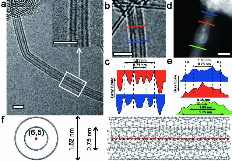
The LLCCs actually always move during the HRTEM observations and therefore appear blurry compared to the DWCNT’s walls. This entails a profile analysis of the empty and filled parts of the DWCNT. In Fig. 1c In Fig. 1c the additional peak shows the difference when the LLCC exists inside DWCNT. Complementary STEM studies on a different tube shown in Fig. 1d and the corresponding scanning blue and red profiles (Fig. 1e) confirm the observation by HRTEM. The green profile corresponds to a thicker tube merging a thinner tube. In this case a third inner tube was formed instead of a LLCC@DWCNT, which was consistently observed in all samples. This allows us generalizing that the HV high temperature nanochemical reactions form LLCCs only for DWCNT with outer diameters below 1.75nm. For slightly thicker DWCNT, triple-walled CNT are formed and significantly larger ones host twisted carbon-clusters (see supplementary information). This establishes the diameter as the key factor in the synthesis of LLCCs. To better visualize this, we have included a model of a LLCC inside a DWCNT with a (6,5) inner tube of 0.75 nm, which is close to the ones observed in HRTEM. Although the HRTEM and STEM are extremely helpful, the fine structure of the LLCC remains elusive due to the movement of the LLCC inside the DWCNT.
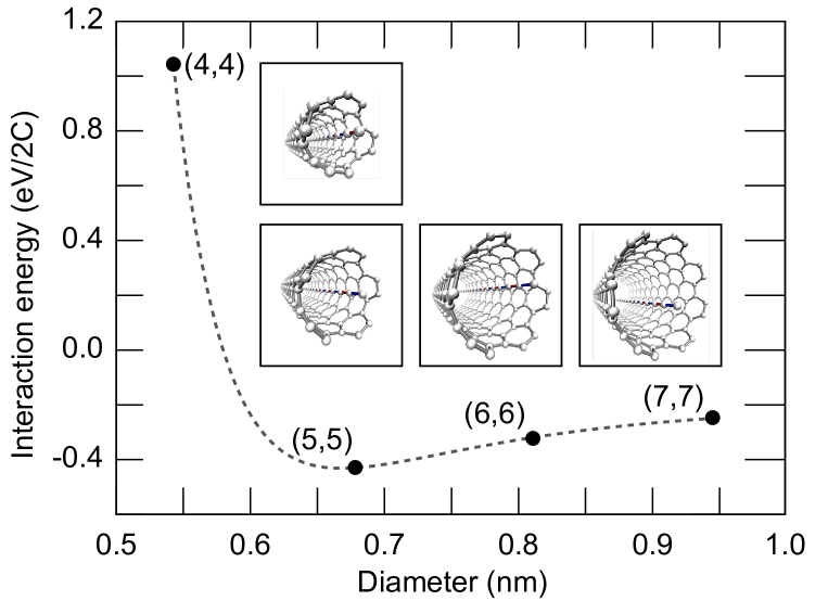
To further understand the effect of confinement on the growth of LLCCs, we performed density functional theory calculations with the Vienna ab–initio simulation package (VASP)[25, 26] using projector augmented wave potentials[27]. The stable chain configuration turned out to be exactly straight, and to contain alternating single and triple bonds with bond lengths of 1.329 Å and 1.229 Å, respectively. We limited our calculations to four small armchair nanotubes, namely, (4,4), (5,5), (6,6) and (7,7) with one repeating unit in the length direction. The interaction energies between the carbon chains and the different nanotubes are plotted in Fig. 2, and the inset shows the illustrations of the LLCC inside different CNTs. The result shows that the optimum distance between adjacent carbons and the CNT is 0.3378 nm, which is very close to the optimum inter-layer distance between graphite layers (0.32 nm), as described in the DFT-D2 method[28]. The LLCC@(5,5) exhibit the lowest interaction energy, which means that a (5,5) nanotube with a diameter of 0.69 nm is the optimum among all four different proposed CNTs for the LLCC–growth. Assuming that the ratio between the carbyne and CNT distance and the inter-layer distance were the same in the calculations and in the experiments (i. e. scaling theoretical values to experimental ones), this would lead to a predicted optimum diameter of 20.33780.320.335 nm = 0.71 nm, which is in a very good agreement with the microscopy outcome.
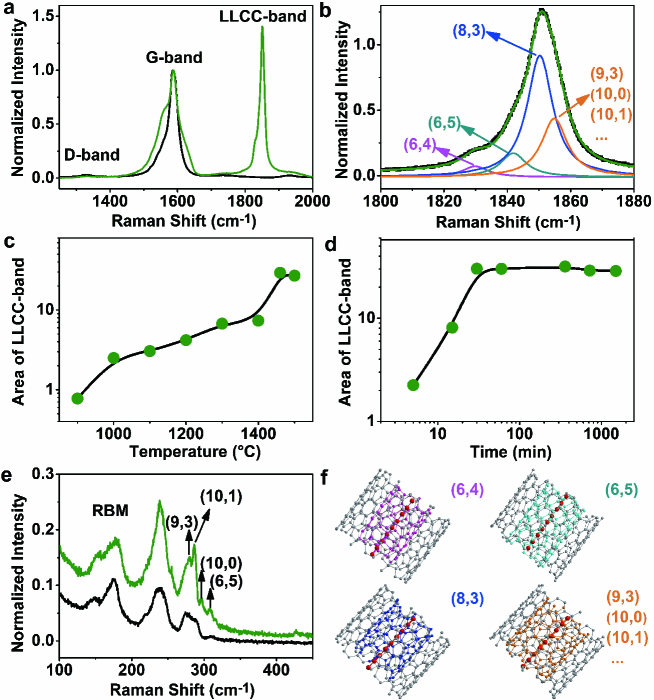
To verify the optimal DWCNT diameter and growth conditions for bulk yield synthesis of LLCCs, resonance Raman spectroscopy was used. The LLCCs exhibit a Raman active mode[21, 19, 23], named hereafter as LLCC-band. Its Raman frequency corresponding is closely associated to the length of the LLCCs and its intensity to the overall yield. Polyyne molecules with less than 20 carbon atoms have vibrational features between 1900-2300 cm-1,[29] whereas in LLCCs consisting of about 100 atoms inside MWCNTs have reported a response at 1825-1850 cm-1.[19] Our multi-frequency studies using a dye laser, confirmed a broad resonance window of the LLCC-band peaking at about 568 nm for LLCC with above 6 different length of acetylenic chains.(see supplementary information). As shown in Fig. 3, inspecting the characteristic D and G bands, corresponding to the defect induced and the graphitic mode of pristine DWCNTs and DWCNTs with LLCCs grown at 1460 (Fig. 3a), the D/G intensity ratio remains practically unchanged. This highlights that the DWCNTs are not damaged during annealing. Moreover, after annealing a very intense LLCC band with fine structure at 1850 cm-1 is observed. A detailed line shape analysis is shown in Fig. 3b. The Raman response of the LLCC-band was always found between 1780 and 1880 cm-1 concomitant with an intensity several times larger than in any previous works on polyynes reaching a record of an even nine times bigger intensity as compared to the DWCNT G-band response at low temperature (see Fig. 4a below). This confirms that the chains are always very long and that their production is feasible in bulk quantities. However, the actual yield of the grown LLCC strongly depends on the growth time and growth temperature in HV. Fig. 3c summarizes the changes in the area of the LLCC-band as a function of annealing temperature. Our new HV method allows to synthesize a small quantity of LLCCs even at a temperature as low as 900. This is consistant with reports on fusion of linear polyynes or adamantane molecules inside DWCNTs at similar temperatures, but those linear structures grow in relatively low yields depending on the filling ratio [21, 22]. The highest area of the LLCC-band indicats that 1460 is the optimal temperature to form LLCCs. Further increasing the annealing temperature leads to a subsequent decomposition of the LLCC@DWCNT structure. Aiming at understanding the growth kinetics of the LLCCs, the pristine DWCNTs were also annealed in HV at the optimal temperature of 1460 for different time. As observed in Fig. 3d, after five minutes annealing, the LLCC-band appears and its intensity increasing for annealing times up to 30 min and saturates afterwards. This suggests that growth of the LLCCs is finished. However, a line shape analysis of the LLCCs (similar to Fig. 3b) revealed that for longer annealing time the relative intensity of the peaks at lower frequency get progressively stronger, indicating the continuous growth of longer chains. The decisive aspects for the LLCC production on top of our studies are: the small-diameter inner tube of our DWCNTs and the annealing in HV, which allows the free carbon atoms having a longer mean free path. It is also worth mentioning that SWCNTs below 0.7 nm diameter are not stable at high temperature and therefore only very few LLCCs can be grown inside them (see supplementary information).
A remaining important question is how the LLCC structure is confined inside the tubes. This missing puzzle piece can be retrieved from an analysis of the radial breathing modes (RBM) of DWCNTs depicted in Fig. 3e. These DWCNTs can be indexed by their chiralities using the Kataura plot and the established inverse proportionality of the tube diameter and the RBM frequency including a correction term for the intertube distance[30, 31]. The indexed RBM peaks corresponding to the thin inner tubes are split and enhanced. This is a first indication of an interaction with the LLCCs. Turning to a detailed analysis of the yield and length distribution of the LLCCs, a tunable dye laser, e.g. with 588.8 and 606.0 nm excitations was used to reveal the full pattern of the LLCC-band (see supplementary information). In general, the LLCC-band position is correlated to the length of the LLCC following the bond length alternation model with a hybrid force field[32]. However, this model is limited regarding an absolute length determination and handles environmental interactions empirically. Considering the interaction between the LLCC and the inner tubes, for thinner host tubes the interaction is larger and therefore a lower frequency is observed. This enables us to tentatively assign the LLCCs fine structure in the line shape analysis of Fig. 3b to different chiralities of inner host tubes. Considering the total energy of the LLCC@DWCNTs, (6,4) tubes are more prone to host longer LLCCs than (6,5). At the same time, a (6,4) tube has larger interaction with its encapsulated LLCC than a (6,5) one. Further exploring the fine structure LLCC band allows estimating the growth yield of different LLCC@DWCNTs via the different relative intensities of the LLCC-bands. This calibration allows easily comparing the growth yields of LLCCs among different samples. This analysis relies on a weak van der Waals coupling between the inner tubes and the LLCCs, which has to be verified.
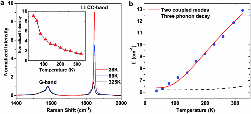
In order to do this, further information on the LLCCs was then sought analysing the temperature dependent Raman response. The intensity and area of LLCC-band are much higher at low temperatures as shown in Fig. 4a. The data recorded from 38 to 325 K are plotted in the inset and show an intensity of 156% of the G-line intensity at room temperature, which increases to 908% of the G-line intensity at 38 K. Concomitantly, it was observed that the full width at half maximum (FWHM, ) gets noticeably narrowed down (Fig. 4b). Normally, the temperature dependence of the FWHM can be analyzed by a classical model of anharmonic decay of optical phonons[33, 34, 35] or a model of a temperature dependent coupling of two modes. As shown in Fig. 4b, the anharmonic decay does not fit our experimental results at all. Hence we describe our results by the second model, i.e. a coupling of the LLCCs mode to the RBM of the inner tubes. The temperature dependence of the FWHM follows the equation with activation energy Ea[36].
As plotted as solid line in Fig. 4b, we find a perfect match for an activation energy Ea of 33.85 meV. This is a clear proof of the coupling of the LLCCs to the inner tubes of the DWCNTs and highlights the importance of the confined nanospace with the right diameter introduced above. This activation energy is also consistent with a weak van der Waals interaction between the tubes and the LLCCs.
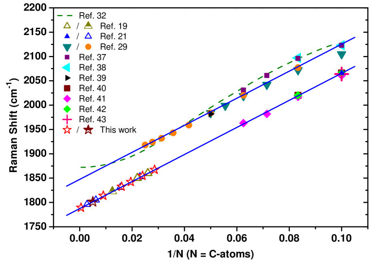
In keeping with these results we are able to put the analysis one step further and unambiguously correlate the length of the LLCCs with the Raman position. In Fig. 5 we compare the Raman positions of different linear carbon chains reported in the literature with the theoretical model from Yang et al.[32] (dashed line) as a function of the inverse carbon atom number. Although there is a qualitative agreement, the limitations of the model are obvious and further precise calculations are needed. However, strikingly we find a very good linear correlation for the line positions of the experimentally proven inverse chain length. This is highlighted by the solid symbols. This linear correlation also counts for LCCs in different environments. LCC inside the same environment follow the same curve, but the LCC in liquid environment is about 60 cm-1 higher in frequency as the ones inside CNT environment.
This allows to assign the length of the long LLCCs by Raman spectroscopy. From our TEM results we know to have DWCNT containing the at least 26 nm LLCC. In order to correlate it with the Raman response we did the most conservative approximation as lowest limit for the chain length and took an extension of the linear fit and assigned the Raman peak at about 1805 cm-1 to the 26 nm chain. We are aware, that for infinitely long chains such a linear approximation is not accurate anymore because of two competing effects. The bond length alternation will saturate, yielding a blue-shift whereas a charge transfer, and hybridisation with the inner tubes will yield a red-shift in the Raman response. Nevertheless, the linear relation is a good first approximation and allows us to assign all other observed Raman signals from our line shape analysis and from the literature to an estimated chain length (open symbols in Fig. 5). This tells us that our highest Raman response corresponds to a chain of at least 40 continuous carbon atoms and we have at lower yield several tubes containing extremely long linear carbon chains of more than 10000 atoms. More detailed calculations will allow to derive the exact anchor point for the chain length. We prove that even with the most conservative estimation we get bulk yield of LLCCs which are at least two order of magnitude longer than those synthesized by an organic chemistry route[11].
While the exact LLCC@DWCNT formation mechanism via HV high temperature nanochemical reactions remains unknown, our in-depth inspection of the material allows us to suggest a model based on the confinement inside the circular nanospace of tubes. Considering the lowest energy principle, carbon atoms can move inside the nanotubes from the open caps or through the tube walls during the HV annealing process. The tubes with diameter of 0.71 nm are the best suited to grow LLCCs as slightly larger tubes tend to form spiral chains or if the tubes are too thick in diameter the tubes are no longer working as nanoreactors and the LLCCs are disintegrating. With our narrow diameter distribution of inner tubes and high yield of small diameter DWCNTs we are able to achieve a bulk production of LLCCs. If uniformed CNTs or the tubes with same chirality are used as the nanoreactors, and providing additional carbon supply, it is a route to achieve the growth of bulk carbyne which might be further extracted from the nanotubes and stabilized in different environments.
Summarizing, we have developed a new route for the first truly bulk production of LLCCs, i.e. carbyne, confined inside DWCNTs. From our Raman and TEM studies with contemporary ab-initio calculations we prove that stability, growth conditions as well as the length and yield of the LLCCs crucially depend on the size confinement. By analyzing the growth temperature dependence, we unambiguously revealed that there is a coupling between the LLCCs and the inner tubes as strongly supported by a model of coupled Raman modes. This allows us to directly correlate the LLCCs length to the diameter of the inner tubes and determine the optimal diameter for the high yield growth of carbyne (about 0.71 nm). Our approach of HV high temperature annealing has a great advantage over filling SWCNT/DWCNT by polyynes and converting them to carbyne because of the superior yield achieving real bulk samples, This is proven by an extremely huge Raman mode with the intensity of more than 900 of the G-band at 38 K in-keeping with a bulk lattice constant of the confined LLCCs chains of d=0.252 nm. Our longest LLCCs can be correlated to a chain length of more than 10000 carbon atoms, which can be seen as the closest realization of carbyne sofar.
Inside the DWCNTs the LLCCs are very stable and with high yield, which is of great important for further applications. Theoretical studies have shown that after inserting LLCCs inside the CNTs, the hybrid system would show metallic character, due to charge transfer from CNTs to the LLCCs, although both of the CNTs and LLCCs perform semiconductor properties themselves[44, 45]. Therefore, we suggest that it is possible to control the electronic properties (tunable band gap) of the hybrid system by different filling yield of LLCCs. Furthermore, quantum spin transport in LLCC can also be a promising application according to the theoretical predictions[46]. Consequently, as true 1D nanocarbon, this novel LLCC@DWCNT system would be, beside the basic interest in chemistry, also a fascinating candidate for the next generation of nanoelectronic devices. As a last point the LLCCs might also be further extracted from the DWCNTs and stabilized in liquid environment later on.
METHODS
0.1 DWCNT synthesis.
DWCNTs were synthesized by high vacuum alcohol chemical vapor deposition. The catalysts were faint yellow powders obtained from the mixture of ammonium iron citrate (Sigma-Aldrich, 3 wt.) and MgO (Sigma-Aldrich, 97 wt.), which were suspended in ethanol, sonicated for 1 hour and calcined at 70 for 24 hours [47]. The powder was then placed in an alumina crucible inside a quartz tube (diameter: 5 cm) for synthesis. The vacuum of the system was always better than 10-7 mbar, when 875 (optimized growth temperature) was reached. An ethanol flow was introduced into the quartz tube for 30 min as carbon source, and the pressure was kept at 70 mbar during synthesis. Typically, 0.5 g of catalyst powder yielded tens of milligrams of DWCNTs after a subsequent purification processes. The first nanotube purification step was done with immersion in HCl (37 wt.). The second consisted in heat treatment in air at 400 for 30 min to remove the amorphous carbon. Black powder was obtained and it was then immersed once again in a HCl solution to remove any residual compound from the catalysts. Subsequently, a last annealing treatment in air was done at 500 for 2 hours to remove completely the amorphous carbon and chemically active SWNTs[47]. Finally, a thin DWCNT buckypaper was prepared by rinsing, filtering and drying.
0.2 Synthesis of LLCC@DWCNTs.
The buckypapers were annealed under high vacuum conditions. Once the optimal synthesis temperature was determined, the pressure was lower than 810-7 mbar at various temperatures (900-1500 ) for 30 min. To understand the growth process and to test the stability of the LLCCs, the DWCNT buckypapers were also annealed at 1460 for different time intervals (5-1500 min).
0.3 Sample characterizations.
Scanning electron microscope (SEM, Zeiss Supra 55 VP) was used to observe the morphology and abundance of CNTs in the as-grown sample. The versatility of resonance Raman spectroscopy was used to study the CNTs and LLCCs. The as-grown, purified DWCNT and HiPco samples were measured with 568.2 (Kr+ laser), 587.2 and 604.3 nm (dye laser, Rhodamine 6G) excitations in ambient conditions using a triple monochromator Raman spectrometer (Dilor XY with a liquid nitrogen cooled CCD detector, without objective lens, 2 mW). All the annealed samples were measured with excitation wavelength of 568.2 nm, because this laser energy is close to the resonance energy of the LLCCs. The slit width was set at 200 m and the spectral resolution was about 2 cm-1. Low temperature Raman spectra was obtained with excitation wavelength of 568.2 nm combined with a cooling system (Modle 22C Cryodyne Cryocooler with a temperature controller: Model DRC-91C). For ease of comparison, all the spectra were normalized according to the intensity of the G-band. Aberration-corrected HRTEM observations operated at 120 kV (2010F, JEOL) were carried out to confirm the purity of the samples and to directly proof the structure of LLCC@DWCNT. STEM (Nion UltraSTEM 100) with a medium annular dark field detector operated at 60 kV was also used to confirm the the structure of LLCC@DWCNT.
0.4 DFT calculations.
To improve our understanding on the optimal nanotube diameter for the growth of LLCCs, we performed density functional theory calculations with the VASP code[25, 26] using projector augmented wave potentials[27]. In order to properly describe the Peierls distortion, we utilized in our simulations the HSE06 hybrid functional for exchange and correlation[48]. The kinetic energy cutoff was set to 500 eV. All of the structures were placed in a 1.5 nm 1.5 nm simulation cell in the xy-plane with the length in the z-direction defined by the equilibrium length for a 2-atomic unit cell of a carbyne chain. The scheme by Monkhorst and Pack was used to generate a -point centered 1114 k-point mesh for the integration in the reciprocal space[49]. Van der Waals interaction was taken into account via the DFT-D2 method of Grimme[50].
Supplementary Information accompanies the paper at www.nature.com/naturematerials
Acknowledgements
This work was supported by the Austrian Science Funds (FWF). L.S. thanks the scholarship supported by the China Scholarship Council. K.S. and Y.N. acknowledge the JST research acceleration programme. J. K. acknowledges FWF for funding through project M 1481-N20, as well as Vienna Scientific Cluster for computational time, and he also thanks Georg Kresse and Martijn Marsman for their help in DFT calculations. We acknowledge Hans Kuzmany for his constructive discussion about the low-temperature Raman spectra of LLCCs@DWCNTs. We thank Stephan Puchegger from the Faculty Center for Nanostructure Research for the support with SEM imaging.
Author Contributions
All authors contributed to this work. L.S. and T.P. designed and supervised the experiments. L.S. prepared the samples. L.S. and P.R. did characterization with Raman. K.S. and Y.N. performed HRTEM characterization. J.K. and J. M. did the STEM measurement. J.K. did the DFT calculations. H.P. did the XRD measurement. L.S., P.A. and T.P. analyzed data and wrote the manuscript and the supplementary information. All authors discussed the results and commented on the manuscript at all stages.
Competing Financial Interests The authors declare that they have no competing financial interests associated to the publication of this manuscript.
Corresponding Author thomas.pichler@univie.ac.at
References
References
- [1] Hirsch, A. The era of carbon allotropes. Nature Mater. 9, 868–871 (2010).
- [2] Kroto, H. W., Heath, J. R., Obrien, S. C., Curl, R. F. & Smalley, R. E. C60: Buckminsterfullerene. Nature 318, 162–163 (1985).
- [3] Iijima, S. Helical microtubules of graphitic carbon. Nature 354, 56–58 (1991).
- [4] Novoselov, K. S. et al. Electric field effect in atomically thin carbon films. Science 306, 666–669 (2004).
- [5] Kasatochkin, V. I., Sladkov, A. M., Kudryavtsev, Y. P., Popov, N. M. & Korshak, V. V. Crystalline forms of a linear modification of carbon. Dokl. Akad. Nauk SSSR+ 177, 358–360 (1967).
- [6] Goresy, A. E. & Donnay, G. A new allotropic form of carbon from ries crater. Science 161, 363–364 (1968).
- [7] Whittaker, A. G. & Kintner, P. L. Carbon: Observations of new allotropic form. Science 165, 589–591 (1969).
- [8] Sladkov, A. & Kudryavtsev, Y. Diamond, graphite, carbyne: Allotropic forms of carbon. Priroda 5, 37–44 (1969).
- [9] Smith, P. P. K. & Buseck, P. R. Graphitic carbon in the allende meteorite: A microstructural study. Science 212, 322–324 (1981).
- [10] Smith, P. P. K. & Buseck, P. R. Carbyne forms of carbon: Do they exist? Science 216, 984–986 (1982).
- [11] Chalifoux, W. A. & Tykwinski, R. R. Synthesis of polyynes to model the sp-carbon allotrope carbyne. Nature Chem. 2, 967–971 (2010).
- [12] Bayer, A. Über polyacetylenverbindungen. Berichte der Deutschen Chemischen Gesellschaft 18, 2269–2281 (1885).
- [13] Liu, M. J., Artyukhov, V. I., Lee, H., Xu, F. B. & Yakobson, B. I. Carbyne from first principles: chain of c atoms, a nanorod or a nanorope. ACS Nano 7, 10075–10082 (2013).
- [14] Baughman, R. H. Dangerously seeking linear carbon. Science 312, 1009–1010 (2006).
- [15] Eisler, S. et al. Polyynes as a model for carbyne: Synthesis, physical properties, and nonlinear optical response. J. Am. Chem. Soc. 127, 2666–2676 (2005).
- [16] Nishide, D. et al. Single-wall carbon nanotubes encaging linear chain C10H2 polyyne molecules inside. Chem. Phys. Lett. 428, 356–360 (2006).
- [17] Kitaura, R., Imazu, N., Kobayashi, K. & Shinohara, H. Fabrication of metal nanowires in carbon nanotubes via versatile nano-template reaction. Nano Lett. 8, 693–699 (2008).
- [18] Chuvilin, A. et al. Self-assembly of a sulphur-terminated graphene nanoribbon within a single-walled carbon nanotube. Nature Mater. 10, 687–692 (2011).
- [19] Zhao, X. L., Ando, Y., Liu, Y., Jinno, M. & Suzuki, T. Carbon nanowire made of a long linear carbon chain inserted inside a multiwalled carbon nanotube. Phys. Rev. Lett. 90, 187401 (2003).
- [20] Endo, M. et al. Nanotube coalescence-inducing mode: A novel vibrational mode in carbon systems. Small 2, 1031–1036 (2006).
- [21] Zhao, C., Kitaura, R., Hara, H., Irle, S. & Shinohara, H. Growth of linear carbon chains inside thin double-wall carbon nanotubes. J. Phys. Chem. C 115, 13166–13170 (2011).
- [22] Zhang, J. et al. Synthesis and transformation of linear adamantane assemblies inside carbon nanotubes. ACS Nano 6, 8674–8683 (2012).
- [23] Shi, L. et al. Ultra-thin double-walled carbon nanotubes: A novel nanocontainer for preparing atomic wires. Nano Res. 4, 759–766 (2011).
- [24] Hu, Y. H. Bending effect of sp-hybridized carbon (carbyne) chains on their structures and properties. J. Phys. Chem. C 115, 1843–1850 (2011).
- [25] Kresse, G. & Furthmüller, J. Efficiency of ab-initio total energy calculations for metals and semiconductors using a plane-wave basis set. Comp. Mater. Sci. 6, 15 – 50 (1996).
- [26] Kresse, G. & Furthmüller, J. Efficient iterative schemes for ab initio total-energy calculations using a plane-wave basis set. Phys. Rev. B 54, 11169–11186 (1996).
- [27] Blöchl, P. E. Projector augmented-wave method. Phys. Rev. B 50, 17953–17979 (1994).
- [28] Graziano, G., Klimes, J., Fernandez-Alonso, F. & Michaelides, A. Improved description of soft layered materials with van der waals density functional theory. J. Phys. Condens. Matter. 24, 424216 (2012).
- [29] Agarwal, N. R. et al. Structure and chain polarization of long polyynes investigated with infrared and raman spectroscopy. J. Raman Spectrosc. 44, 1398–1410 (2013).
- [30] Kuzmany, H. et al. Determination of swcnt diameters from the raman response of the radial breathing mode. Eur. Phys. J. B 22, 307–320 (2001).
- [31] Araujo, P. T. et al. Nature of the constant factor in the relation between radial breathing mode frequency and tube diameter for single-wall carbon nanotubes. Phys. Rev. B 77, 241403 (2008).
- [32] Yang, S. J., Kertesz, M., Zolyomi, V. & Kürti, J. Application of a novel linear/exponential hybrid force field scaling scheme to the longitudinal raman active mode of polyyne. J. Phys. Chem. A 111, 2434–2441 (2007).
- [33] Cowley, R. A. Raman scattering from crystals of diamond structure. J. Phys.-Paris 26, 659–667 (1965).
- [34] Klemens, P. G. Anharmonic decay of optical phonons. Phys. Rev. 148, 845–848 (1966).
- [35] Balkanski, M., Wallis, R. F. & Haro, E. Anharmonic effects in light-scattering due to optical phonons in silicon. Phys. Rev. B 28, 1928–1934 (1983).
- [36] Kuzmany, H. Solid-State Spectroscopy: An Introduction (Springer-Verlag, Berlin Heidelberg, 1998).
- [37] Tabata, H., Fujii, M., Hayashi, S., Doi, T. & Wakabayashi, T. Raman and surface-enhanced raman scattering of a series of size-separated polyynes. Carbon 44, 3168–3176 (2006).
- [38] Wakabayashi, T. et al. Resonance raman spectra of polyyne molecules C10H2 and C12H2 in solution. Chem. Phys. Lett. 433, 296–300 (2007).
- [39] Gibtner, T., Hampel, F., Gisselbrecht, J. P. & Hirsch, A. End-cap stabilized oligoynes: Model compounds for the linear sp carbon allotrope carbyne. Chem. Eur. J. 8, 408–432 (2002).
- [40] Malard, L. M. et al. Resonance raman study of polyynes encapsulated in single-wall carbon nanotubes. Phys. Rev. B 76, 233412 (2007).
- [41] Wakabayashi, T. et al. Raman spectral features of longer polyynes hC2nh (n=4-8) in swnts. Eur. Phys. J. D 52, 79–82 (2009).
- [42] Nishide, D. et al. Raman spectroscopy of size-selected linear polyyne molecules C2nH2 (n=4-6) encapsulated in single-wall carbon nanotubes. J. Phys. Chem. C 111, 5178–5183 (2007).
- [43] Moura, L. G. et al. Dielectric screening in polyynes encapsulated inside double-wall carbon nanotubes. Phys. Rev. B 83, 245427 (2011).
- [44] Rusznyák, ., Zolyomi, V., Kürti, J., Yang, S. & Kertesz, M. Bond-length alternation and charge transfer in a linear carbon chain encapsulated within a single-walled carbon nanotube. Phys. Rev. B 72, 155420 (2005).
- [45] Tapia, A. et al. Density functional study of the metallization of a linear carbon chain inside single wall carbon nanotubes. Carbon 48, 4057–4062 (2010).
- [46] Zanolli, Z., Onida, G. & Charlier, J. C. Quantum spin transport in carbon chains. ACS Nano 4, 5174–5180 (2010).
- [47] Endo, M. et al. ’buckypaper’ from coaxial nanotubes. Nature 433, 476 (2005).
- [48] Paier, J. et al. Screened hybrid density functionals applied to solids. J. Chem. Phys. 124, 154709 (2006).
- [49] Monkhorst, H. J. & Pack, J. D. Special points for brillouin-zone integrations. Phys. Rev. B 13, 5188–5192 (1976).
- [50] Grimme, S. Semiempirical gga-type density functional constructed with a long-range dispersion correction. J. Comput. Chem. 27, 1787–1799 (2006).
Figure Legends
Figure1: Direct observation of LLCC@DWCNT. a, HRTEM image of a LLCC@DWCNT with bending. The LLCC inside a DWCNT is longer than 26 nm, which means that it consists of more than 200 continuous carbon atoms. Inset: A close view of the image in the marked box. b, Another part of DWCNT with half filling of LLCC. c, The line profiles at positions along the blue and red lines shown in b, represent empty DWCNT and LLCC@DWCNT, respectively. d, The STEM image of a LLCC@DWCNT. e, The line profiles at positions along the blue, red and green lines shown in (d), represent empty DWCNT, LLCC@DWCNT and a thin most-inner tube@DWCNT, respectively. f, Molecular model of LLCC@DWCNT with (6,5) inner tube. Scale bar: 2 nm.
Figure2: Calculation of the optimum diameter for LLCC encapsulated in CNT. DFT calculations about the interaction energies between the LLCC and different chirality tubes: (4,4), (5,5), (6,6) and (7,7). The inset: illustrations of different CC@CNT structures. Notice that the distance between the LLCC and the wall of the CNT remains similar for all host CNT. For the energy minimum, this distance is close to the radius of the CNT.
Figure3: Raman spectra of LLCC@DWCNTs. These measurements were done using a 568.2 nm excitation wavelength. a, D-band, G-band and LLCC-bands of a sample annealed at 1460 as compared to a pristine DWCNT. b, LLCC-band line shape analysis including four components. c, The area of the LLCC-band as a function of annealing temperature for 30 min annealing time. d, The area of the LLCC-band as a function of annealing time at 1460 . e, RBM region for a sample annealed at 1460 . f, Models of our most abundant inner-tube-chiralites and chain configurations.
Figure 4 The temperature dependence of LLCC-band. a, Raman spectra of LLCC@DWCNTs measured at different temperatures. The spectra are are normalized to the G-band response. The inset shows the LLCC-band intensity in comparison to the G-line. b, FWHM of the individual components in LLCC-band as a function of temperature. The solid line represents a model of a temperature dependent coupling two coupled modes, the dashed curve represents a fit to a model of a three-phonon decay.
Figure 5: Comparison of the inverse lengths of linear carbon chains with the Raman response. Raman response of polyynes as function of inverse length given by the number of carbon atoms. The solid lines correspond to a linear fit. The top line includes the data related to chains that are saturated or suspended in a fluid medium [37, 38, 29, 39]. The lower line contains studies all embracing nanotubes taking into account an additional downshift of 60 cm-1 due to the interaction with the inner tubes. The solid symbols are experimental results with confirmed length [40, 41, 42, 43, 21] and the empty symbols correspond to the LLCC@DWCNTs reported in this work and for LLCC@D/MWCNT [21, 19]. The partly solid symbols are experimental results with length estimated by TEM. The dashed line corresponds to a theoretical model using the bond length alternation from Yang. et al.[32].